Think 3D STORMBEE User manual

STORMBEE
Software User Manual
Think 3D BVBA
30/09/2018

STORMBEE Software User Manual –Think 3D BVBA
Version N°1.1, last modified 30/09/2018
ii
PAGE INTENTIONALLY LEFT BLANK

STORMBEE Software User Manual –Think 3D BVBA
Version N°1.1, last modified 30/09/2018
iii
Version control
Author
Date
Version
Comments/Adaptations
Jon Verbeke
26/04/2018
1.0
Initial version
Jon Verbeke
30/09/2018
1.1
Updated to S20 production model

STORMBEE Software User Manual –Think 3D BVBA
Version N°1.1, last modified 30/09/2018
iv
PAGE INTENTIONALLY LEFT BLANK

STORMBEE Software User Manual –Think 3D BVBA
Version N°1.1, last modified 30/09/2018
v
Table of Contents
Version control........................................................................................................................................iii
List of figures ..........................................................................................................................................vii
List of tables ............................................................................................................................................xi
Symbols and abbreviations ...................................................................................................................xiii
1 Introduction..................................................................................................................................... 1
1.1 System requirements .............................................................................................................. 1
1.2 General workflow postprocessing........................................................................................... 1
2 Extracting data from FARO scanner and GNSS module .................................................................. 3
2.1 Extracting data from FARO scanner ........................................................................................ 3
2.1.1 Extraction......................................................................................................................... 3
2.1.2 Format ............................................................................................................................. 4
2.2 Extracting data from GNSS module......................................................................................... 5
3 Applanix POSPac UAV.................................................................................................................... 11
3.1 Installation POSPac UAV........................................................................................................ 11
3.2 Importing GPS trajectories .................................................................................................... 12
3.3 Processing raw GNSS data to refined GNSS data.................................................................. 17
3.3.1 Single base processing................................................................................................... 18
3.3.2 SmartBase processing.................................................................................................... 25
3.3.3 Own base station processing......................................................................................... 35
3.3.4 Quality control............................................................................................................... 36
3.3.5 Data export.................................................................................................................... 42
3.4 Troubleshooting .................................................................................................................... 44
3.4.1 Import error................................................................................................................... 44
3.4.2 Checking message logs for errors after import ............................................................. 45
3.4.3 Too few satellites (below five) ...................................................................................... 47
4 BEEFLEX ......................................................................................................................................... 49
4.1 Installation............................................................................................................................. 49
4.2 Data processing ..................................................................................................................... 51
5 Visualisation (refined) point cloud ................................................................................................ 57
5.1 CloudCompare information................................................................................................... 57
5.1.1 Install Cloud Compare software.................................................................................... 57
5.1.2 Visualize cloud point data ............................................................................................. 57

STORMBEE Software User Manual –Think 3D BVBA
Version N°1.1, last modified 30/09/2018
vi
5.2 Visualisation postprocessed point cloud............................................................................... 57
5.2.1 Import data files ............................................................................................................ 57
5.2.2 Verify accuracy results................................................................................................... 59
5.3 Examples post-processed data.............................................................................................. 68
6 STORMBEE and FARO scanner calibration procedure................................................................... 71

STORMBEE Software User Manual –Think 3D BVBA
Version N°1.1, last modified 30/09/2018
vii
List of figures
Figure 1.1 STORMBEE post-processing software workflow.................................................................... 2
Figure 2.1 Remove SD-card from FARO scanner..................................................................................... 3
Figure 2.2 Insert SD-card into computer................................................................................................. 4
Figure 2.3 FARO scanner data *.fls folder structure ............................................................................... 4
Figure 2.4 Data extraction: connect battery ........................................................................................... 5
Figure 2.5 Data extraction: turn on GNSS avionics and connect ethernet cable.................................... 6
Figure 2.6 Ethernet settings 1 ................................................................................................................. 6
Figure 2.7 Ethernet settings 2 ................................................................................................................. 7
Figure 2.8 Ethernet settings 3 ................................................................................................................. 7
Figure 2.9 FileZilla open site manager..................................................................................................... 8
Figure 2.10 FileZilla site manager settings .............................................................................................. 8
Figure 2.11 FileZilla connect to STORMBEE............................................................................................. 9
Figure 2.12 FileZilla select files and drag to left screen .......................................................................... 9
Figure 2.13 FileZilla file transfer progress ............................................................................................. 10
Figure 2.14 FileZilla file transfer succesful ............................................................................................ 10
Figure 3.1 Applanix base stations worldwide........................................................................................ 11
Figure 3.2 Applanix license activation step 1 ........................................................................................ 12
Figure 3.3 Applanix license activation step 2 ........................................................................................ 13
Figure 3.4 Applanix new default project ............................................................................................... 13
Figure 3.5 Importing GNSS data files from PosPac ribbon.................................................................... 14
Figure 3.6 Applanix GNSS data import progress window 1................................................................... 14
Figure 3.7 Applanix GNSS data import progress window 2................................................................... 15
Figure 3.8 Applanix GNSS antenna used ............................................................................................... 15
Figure 3.9 Applanix trajectory with zoomed view of orange event triangles ....................................... 16
Figure 3.10 Applanix import failure error message .............................................................................. 16
Figure 3.11 Applanix IMU data continuity check error message .......................................................... 16
Figure 3.12 Applanix processing initialisation settings ......................................................................... 17
Figure 3.13 Applanix GNSS-Inertial processor button........................................................................... 17
Figure 3.14 Applanix GNSS-Inertial processor Single Base.................................................................... 18
Figure 3.15 Applanix data base import options .................................................................................... 18
Figure 3.16 Applanix data base import high-rate data sites ................................................................. 19
Figure 3.17 Applanix data base import single base............................................................................... 20
Figure 3.18 Applanix data base stations import list.............................................................................. 21
Figure 3.19 Applanix single base station w.r.t. mission trajectory view............................................... 21
Figure 3.20 Applanix set single base station ......................................................................................... 22
Figure 3.21 Applanix single base station data quality analysis ............................................................. 23
Figure 3.22 Applanix GNSS-inertial processor processing..................................................................... 23
Figure 3.23 Applanix GNSS-Inertial processing completed................................................................... 24
Figure 3.24 Applanix GNSS-Inertial processor SmartBase..................................................................... 26
Figure 3.25 Applanix data base import options .................................................................................... 26
Figure 3.26 Applanix data base import high-rate data sites ................................................................. 27
Figure 3.27 Applanix data base import SmartBase ............................................................................... 27

STORMBEE Software User Manual –Think 3D BVBA
Version N°1.1, last modified 30/09/2018
viii
Figure 3.28 Applanix data base stations import list.............................................................................. 28
Figure 3.29 Applanix set SmartBase control station ............................................................................. 29
Figure 3.30 Applanix GNSS-inertial processor processing SmartBase .................................................. 30
Figure 3.31 Applanix SmartBase website.............................................................................................. 30
Figure 3.32 Applanix SmartBase Login and register for free................................................................. 31
Figure 3.33 Applanix SmartBase Login.................................................................................................. 31
Figure 3.34 Applanix SmartBase search mission location..................................................................... 32
Figure 3.35 Applanix SmartBase mission location ................................................................................ 32
Figure 3.36 Applanix SmartBase mission location marker.................................................................... 33
Figure 3.37 Applanix SmartBase preview SmartBase button................................................................ 33
Figure 3.38 Applanix SmartBase VRS info ............................................................................................. 34
Figure 3.39 Applanix SmartBase VRS request window ......................................................................... 34
Figure 3.40 Applanix SmartBase VRS data (full).................................................................................... 35
Figure 3.41 Applanix SmartBase VRS data to import in POSPac ........................................................... 35
Figure 3.42 Applanix quality control generate diagnostic report ......................................................... 36
Figure 3.43 Applanix quality control display plots overview................................................................. 37
Figure 3.44 Applanix quality control display plot RMSE........................................................................ 38
Figure 3.45 Applanix quality control display plot number of satellites................................................. 39
Figure 3.46 Applanix quality lever arm settings.................................................................................... 40
Figure 3.47 Applanix quality control display plot PDOP........................................................................ 40
Figure 3.48 Applanix quality control display plot cycle slips................................................................. 41
Figure 3.49 Applanix export LIDAR event data (for BEEFLEX processing)............................................. 42
Figure 3.50 Applanix export trajectory data (for BEEFLEX processing) step 1...................................... 43
Figure 3.51 Applanix export trajectory data (for BEEFLEX processing) step 2...................................... 43
Figure 3.52 Applanix import failure error message .............................................................................. 44
Figure 3.53 Applanix import error split file program ............................................................................ 44
Figure 3.54 Applanix import error split files.......................................................................................... 45
Figure 3.55 Applanix opening message logs dropdown menu.............................................................. 45
Figure 3.56 Applanix message log POS data import.............................................................................. 45
Figure 3.57 Applanix message log IMU data continuity checking (step 1)............................................ 46
Figure 3.58 Applanix message log IMU data continuity checking (step 2)............................................ 46
Figure 3.59 Applanix satellite elevation mask angle ............................................................................. 47
Figure 4.1 BEEFLEX program folder structure....................................................................................... 49
Figure 4.2 BEEFLEX license activation and management...................................................................... 50
Figure 4.3 BEEFLEX start screen ............................................................................................................ 50
Figure 4.4 Folder containing all files required by BEEFLEX ................................................................... 51
Figure 4.5 BEEFLEX select folder flight and scan data........................................................................... 51
Figure 4.6 BEEFLEX import raw scan data and convert to *.e57-format .............................................. 52
Figure 4.7 BEEFLEX flight and scan data general overview................................................................... 52
Figure 4.8 BEEFLEX flight and scan data general overview (satellite view) .......................................... 53
Figure 4.9 BEEFLEX data import possible error messages..................................................................... 53
Figure 4.10 BEEFLEX select relevant section of flight............................................................................ 54
Figure 4.11 BEEFLEX select multiple sections of flight.......................................................................... 54
Figure 4.12 BEEFLEX data processing run information window............................................................ 55
Figure 4.13 BEEFLEX data processing progress E57-format.................................................................. 56

STORMBEE Software User Manual –Think 3D BVBA
Version N°1.1, last modified 30/09/2018
ix
Figure 4.14 BEEFLEX data processing progress LAS-format.................................................................. 56
Figure 4.15 BEEFLEX refined point cloud data folder structure............................................................ 56
Figure 5.1 CloudCompare import files through desktop icon............................................................... 58
Figure 5.2 CloudCompare import point cloud properties window ....................................................... 58
Figure 5.3 CloudCompare import point cloud progress........................................................................ 59
Figure 5.4 CloudCompare visualisation refined point clouds................................................................ 59
Figure 5.5 CloudCompare selection flight (segment)............................................................................ 60
Figure 5.6 CloudCompare flight (segment) colour selection window................................................... 60
Figure 5.7 CloudCompare flight (segments) with unique colours......................................................... 61
Figure 5.8 CloudCompare selecting all point clouds in Navigation menu............................................. 61
Figure 5.9 CloudCompare all point clouds selected in navigation menu.............................................. 62
Figure 5.10 CloudCompare point cloud cross-section .......................................................................... 62
Figure 5.11 CloudCompare cross-section properties window .............................................................. 63
Figure 5.12 CloudCompare point cloud with cross-section properties window and interactors ......... 63
Figure 5.13 CloudCompare point cloud cross-section narrow slice...................................................... 64
Figure 5.14 CloudCompare point cloud slice zoomed in (10 meter)..................................................... 64
Figure 5.15 CloudCompare cross-section zoomed in (1 meter)............................................................ 65
Figure 5.16 CloudCompare cross-section in-plane quality control....................................................... 65
Figure 5.17 CloudCompare point cloud cross-section narrow slice (example 2).................................. 66
Figure 5.18 CloudCompare point cloud slice zoomed in (example 2)................................................... 67
Figure 5.19 CloudCompare cross-section in-plane quality control (example 2)................................... 67
Figure 5.20 Final post-processed point cloud ....................................................................................... 68
Figure 5.21 3D model based on final post-processed point cloud data................................................ 68
Figure 5.22 2D drawing based on final post-processed point cloud data............................................. 69
Figure 6.1 STORMBEE hastag (#) calibration flight path example......................................................... 71
Figure 6.2 Folder containing all files required by BEEFLEX ................................................................... 72
Figure 6.3 FARO scanner calibration "config.ini" file ............................................................................ 72
Figure 6.4 FARO scanner calibration parameters (heading, pitch and roll).......................................... 73

STORMBEE Software User Manual –Think 3D BVBA
Version N°1.1, last modified 30/09/2018
x
PAGE INTENTIONALLY LEFT BLANK

STORMBEE Software User Manual –Think 3D BVBA
Version N°1.1, last modified 30/09/2018
xi
List of tables
N/A

STORMBEE Software User Manual –Think 3D BVBA
Version N°1.1, last modified 30/09/2018
xii
PAGE INTENTIONALLY LEFT BLANK

STORMBEE Software User Manual –Think 3D BVBA
Version N°1.1, last modified 30/09/2018
xiii
Symbols and abbreviations
GNSS Global Navigation Satellite System
GPS Global Positioning System
IMU Inertial Measurement Unit
RAM Random-Access Memory

STORMBEE Software User Manual –Think 3D BVBA
Version N°1.1, last modified 30/09/2018
xiv
PAGE INTENTIONALLY LEFT BLANK

STORMBEE Software User Manual –Think 3D BVBA
Version N°1.1, last modified 30/09/2018
1
1Introduction
1.1 System requirements
We recommend a performant laptop/desktop to perform all processing with as visualising the point
clouds and processing all data is very demanding on the processor and graphical card and requires a
lot of RAM.
Recommended specs (based on most demanding software package FARO Scene):
•Processor: Quad-core X64, Intel Core i7/Xeon, 8 physical cores
•Graphics Card: Dedicated graphics card, OpenGL 4.1 or higher, at least 4 GB Memory,
oFor Stereo Rendering: NVIDIA Quadro;
oFor VR Rendering: NVIDIA 1080GTX or similar, Oculus Rift or HTC Vive with Touch
Controllers, SteamVR must be installed
•Main memory: 64 GB RAM
•Hard Disk Drive: 512 GB Solid State Drive + Regular HDD
•Operating System: 64-bit Windows™ 7 SP1 or higher
•Screen resolution: 1920×1080
1.2 General workflow postprocessing
The general workflow for postprocessing the laser scanner data is shown in Figure 1.1 .

STORMBEE Software User Manual –Think 3D BVBA
Version N°1.1, last modified 30/09/2018
2
Figure 1.1 STORMBEE post-processing software workflow

STORMBEE Software User Manual –Think 3D BVBA
Version N°1.1, last modified 30/09/2018
3
2Extracting data from FARO scanner and GNSS module
2.1 Extracting data from FARO scanner
2.1.1 Extraction
1. Ensure that the FARO scanner is powered off.
2. Remove the SD card of the FARO scanner. Please refer to the manual of your specific FARO
scanner on how to do this.
Figure 2.1 Remove SD-card from FARO scanner

STORMBEE Software User Manual –Think 3D BVBA
Version N°1.1, last modified 30/09/2018
4
3. Plug the SD-card into an SD-card reader connected with your laptop. Copy the data to your
laptop in a folder of your choice.
Figure 2.2 Insert SD-card into computer
2.1.2 Format
The FARO scanner data is stored within a folder named “***.fls”. It should contain several files and
subfolders. Each “*.fls” folder represents a single STORMBEE flight (Figure 2.3).
Figure 2.3 FARO scanner data *.fls folder structure

STORMBEE Software User Manual –Think 3D BVBA
Version N°1.1, last modified 30/09/2018
5
2.2 Extracting data from GNSS module
Data retrieval uses FileZilla Client Basic (or equivalent) software. Please download and install program
from https://filezilla-project.org/.
1. Connect battery (1 is sufficient)
Figure 2.4 Data extraction: connect battery
2. On the STORMBEE, power on the GNSS avionics (and FARO Focus scanner) by pressing the
large button with the power symbol on it.
STORMBEE Software User Manual –Think 3D BVBA
Version N°1.1, last modified 30/09/2018
6
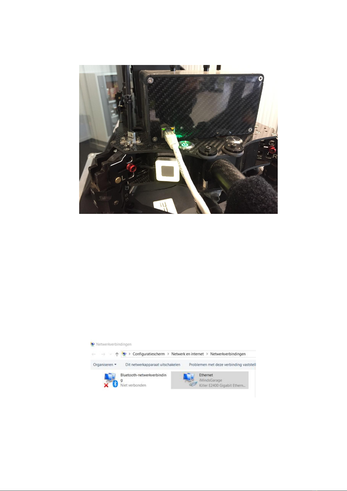
3. Wait until the large LED is blinking and then connect the ethernet cable from the GNSS avionics
box to your PC.
Figure 2.5 Data extraction: turn on GNSS avionics and connect ethernet cable
4. You should verify that the adapter settings of your ethernet port are set to the correct fixed IP
address. Otherwise FileZilla cannot connect to it. Open your Windows settings page and left-
click on "network and internet settings". Go to page "Ethernet". Click on "Change adapter
options". You should now see the adapters (usually "Bluetooth", "Ethernet" and "Wi-Fi").
Right-click on "Properties. Select "Internet Protocol version 4 (TCP/IPv4" and click below on
"Properties". You should now see the IP and DNS properties window. Here is where you need
to set the manual IP address to be able to connect with STORMBEE. Usually this will be set to
"apply automatic IP and DNS addresses". If it is filled in with other values or you use an
ethernet cable for internet then you should remember to revert the following changes
afterwards. Otherwise your (wired) internet connection might not work anymore. The settings
don't affect your Wi-Fi connections. Set IP-address to "192.168.53.101" and subnet mask to
"255.255.255.0". Leave the rest empty. Press OK until all windows are closed.
Figure 2.6 Ethernet settings 1
Table of contents
Other Think 3D Drone manuals


