Thinuna PX-3000 User manual

PX-3000 AUDIO MATRIX
RM-3088 REMOTE MICROPHONE STATION
LM-3088A REMOTE WALL PANEL
Technology
Innovative, Advanced, Reliable...
version:1.1


Contens
Welcome........................................................................................................................................................................................................1
Warning..........................................................................................................................................................................................................1
Installation.....................................................................................................................................................................................................2
Import safety instructions........................................................................................................................................................................2
PX-3000 Audio Matrix
Overview.........................................................................................................................................................................................................3
Front panel.................................................................................................................................................................................................... 4
Rear panel.......................................................................................................................................................................................................5
Audio screen description...........................................................................................................................................................................7
Task screen description..............................................................................................................................................................................9
Device screen description...................................................................................................................................................................... 10
Monitoring screen description..............................................................................................................................................................11
Setting screen description.....................................................................................................................................................................12
SD card playing screen description.....................................................................................................................................................14
RM-3088 Remote Microphone Station
Front panel .................................................................................................................................................................................................16
Rear panel....................................................................................................................................................................................................17
Main screen description......................................................................................................................................................................... 18
SD card VOD screen description.........................................................................................................................................................20
Control screen description.....................................................................................................................................................................21
Setting screen description......................................................................................................................................................................22
LM-3088A Remote Wall Panel
Main screen description..........................................................................................................................................................................24
Audio select screen description........................................................................................................................................................... 25
Local input EQ screen description.......................................................................................................................................................26
Setting screen description..................................................................................................................................................................... 26
20 bus Assistant PC setup Software
Software setup for windows.................................................................................................................................................................28
Software menu description....................................................................................................................................................................31
Configuration section description.......................................................................................................................................................32
Setting section description....................................................................................................................................................................37
Specification................................................................................................................................................................................................39
Block diagram.............................................................................................................................................................................................40
Application..................................................................................................................................................................................................41
Connections................................................................................................................................................................................................42
Quick start guide.......................................................................................................................................................................................43
Connection of phoenix connector...................................................................................................................................................... 45
Connection of volume controller override.......................................................................................................................................46
Service...........................................................................................................................................................................................................47
www.thinuna.com Page 1 Version A
Thanks you for choosing our products, we will always provide innovative, advanced, reliable products like before.
We are sincerely trust these products will provide years of satisfactory service, but if anything is not to your
complete satisfaction, we will endeavor to make things right.
Welcome to us again, and thank you for becoming part of our worldwide extended family!
Welcome
Warning
CAUTION
.
RISK OF ELECTRIC
SHOCK DON’T OPEN
This symbol is intended to alert the user to the
presence of uninsulated “dangerous voltage” within
the product’s enclosure that may be of suf-ficient
magnitude to constitute a risk of electric shock to
persons.
This symbol is intended to alert the user to the
presence of important operation and mainte-nance
(servicing) instructions in the literature accompanying
the appliance.
* Do not install this equipment in a confined space such as a book case or similar unit.
* The apparatus shall not be exposed to dripping or splashing and no objects filled with liquids, such vases, shall be placed on the apparatus.
* Worded: “WARNING FOR YOUR PROTECTION PLEASE READ THE FOLLOWING-WATER AND MOISTURE: Unit should not be used
near water(e.g. near a bathtub, washbowl, kitchen sink, laundry tub, in a wet basement, or near a swimming pool, etc).
Care should be taken so than objects do not fall and liquids are not spilled into the enclosure through openings.”
Service Instructions
* Worded: "Caution: These servicing instructions are for use by qualified service personnel only. To reduce the risk of electric shock, do not
perform any servicing other than that contained in the operating instructions unless you are qualified to do so."
* Location: Instruction Manual.
NOTE : This equipment has been tested and found to comply with the limits for a Class A digital device, pursuant to Part 15 of the FCC Rules.
These limits are designed to provide reasonable protection against harmful interference when the equipment is operated in a commercial
environment. This equipment generates, uses, and can radiate radio frequency energy and, if not installed and used in accordance with the
instruction manual, may cause harmful interference to radio communications. Operation of this equipment in a residential area is likely to
cause harmful interference in which case the user will be required to correct the interference at his own expense.
Attentions: Pour prévenir les chocs électriques ne pas utiliser cette
fiche polarisée avec un prolongateur, une prise de courant
on une autre sortie de courant, sauf si les lames peuvent
étre insérées à fond sans en laisser aucune partie à
découvert.
To prevent fire or shock hazard, do not
expose the unit to rain or moisture.
WARNING
CAUTION: TO REDUCE THE RISK OF ELECTRIC SHOCK.
DO NOT REMOVE COVER (OR BACK).
NO USER-SERVICEABLE PARTS INSIDE.
REFER SERVICING TO QUALIFIED SERVICE PERSONNEL.
Caution: To prevent electric shock do not use this (polarized) plug with
an extension cord, receptacle or other outlet unless the blades
can be fully inserted to prevent blade expo-sure.

Page 2 Version A www.thinuna.com
Installation Environment
Important Safety Instructions
- Avoid excessive heat, humidity, dust and vibration
Keep the unit away from locations where it is likely to be exposed to high temperatures or humidity-such as
near radiators, stoves, etc. Also avoid locations which are subject to excessive dust accumulation, or to vibration
that could cause mechanical damage.
- Avoid physical shocks
Strong physical shocks to the unit may cause damage. Handle the unit with care.
- Do not open the case or attempt repairs or modifications yourself
This product contains no user-serviceable parts. Refer all maintenance to qualified our service personnel.
Opening the case and/or tampering with internal circuitry voids the warranty.
- Always power off before making connections
Always turn the AC mains OFF before connecting or disconnecting cables. This is important to prevent damage
to the unit itself as well as other connected equipment.
- Handle cables carefully
Always plug and unplug cables (including the AC mains power cord) by gripping the connector, not the cord.
- Clear with a soft dry cloth
Never use solvents such as benzine or paint thinner to clean the unit. Wipe clean with a soft, dry cloth.
Installation this system is not difficult and complex. But you still need to spend some time to read this manual and
ensure the connection and installation is exact.
Never place this product in an environment which could alter its performance or reduce its service life.
Such environments usually include high levels of heat, dust, moisture, and vibration.
1. Read these instructions.
2. Keep these instructions.
3. Heed all warnings.
4. Follow all instructions.
5. Do not use this apparatus near water.
6. Clean only with dry cloth.
7. Do not block any ventilation openings. Install in accordance with the manufacturer’s instructions.
8. Do not install near any heat sources such as radiators, heat registers, stoves, or other apparatus
(including amplifiers) that produce heat.
9. Do not defeat the safety purpose of the polarized or grounding-type plug. A polarized plug has two blades with
one wider than the other. A grounding type plug has two blades and a third grounding prong.
The wide blade or the third prong are provided for your safety. If the provided plug does not fit into your outlet,
consult an electrician for replacement of the obsolete outlet.
10. Protect the power cord from being walked on or pinched particularly at plugs, convenience receptacles, and the
point where they exit from the apparatus.
11. Only use attachments/accessories specified by the manufacturer.
12. Use only with the cart, stand, tripod, bracket, or table specified by the manufacturer, or sold with the apparaus.
When a cart is used, use caution when moving the cart/apparatus combination to avoid injury from tip-over.
13. Unplug this apparatus during lightning storms or when unused for long periods of time.
14. Refer all servicing to qualified service personnel. Servicing is required when the apparatus has been damaged in
any way, such as power-supply cord or plug is damaged, liquid has been spilled or objects have fallen into the
apparatus, the apparatus has been exposed to rain or moisture, does not operate normally, or has been dropped.

SYSTEM OVERVIEW
Audio Matrix Part
Page 3 Version A www.thinuna.com
The PX-3000 series audio matrix (20 bus voice alarm system) is a new public address system and commercial audio
system with highly competitive. The audio and control signal are based on the bus-type to transfer, therefore this
whole system with excellent feature including: compact device, high integration, powerful functions, flexible and
convenient control, completed logic control port. For the contractor and the audio designer, It’s biggest selling-
points is Simple and Intuitive. Make the design and the use of PA-system become more and more easy.
PX-3000 system can be applied on public address system which required multi channels audio streaming
simultaneously. The PX-3000 is suitable for the system weather the application is big or small. This system can be used
on the high building, hotel, bus station, entertainment venues, hospital, convention center, restaurant, school, etc.
The mail controller(8x8 audio matrix including the functions as: pre-amp, equalizer, zones selector, remote
microphone station interface, remote wall panel interface, monitor speaker, 3 ware and 4 wire volume controller
override, fire alarm or emergency message, logic output and input, etc. Through it’s link function, max 32 pcs audio
matrix controller can be linked and up to 256 zones can be supported. Max 8 pcs Microphone station can be
connected to the master audio matrix, also 0-8 pcs remote wall panel can be connected into each zone.
System equipment as below:
1. 8X8 audio matrix (PX-3000, max 32pcs can be linked and extend up to 256 zones)
2. Microphone station (RM-3088, max support 8 pcs, can be set as business or emergency paging microphone station)
3. Remote wall control panel (LM-3088A, each zones can connect 0-8 pcs)
6 steps priority control (high priority will override lower priority, same priority can be arranged)
1. Emergency paging microphone station (when RM1-8 are set to be emergency microphone)
2. Automatic fire alarm (Pre-recorded fire message in SD2 or external fire audio input)
3. Business microphone station (when RM1-8 are set to be business microphone)
4. Timer audio (Timing source from built-in SD1 or external timer audio source)
5. Remote panel (LM-3088A, each branch area can connect 0-8 of panel)
6. BGM source (AUX1-8 and built-in SD1 source of master audio matrix)
System capacity:
The master audio matrix provide 20bus audio inputs: AUX1-8, SD1, RM1-8, SD2 built-in fire alarm, external
timing, external fire alarm. All the slaver matrix share the 20bus from master audio matrix. Max 32pcs audio matrix can
be linked and extend up to 256 zones. Each zone can connect 0-8 pcs remote wall panel which communication
distance is 1000 meters, power by the matrix or external power supply.
Technical Support (Settings and operations)
The system comes with fully functional, simple operation, good interactive interface and remote control software. All
functions can be set and controlled by PC software. It supports different permissions levels for operators and provides
password.
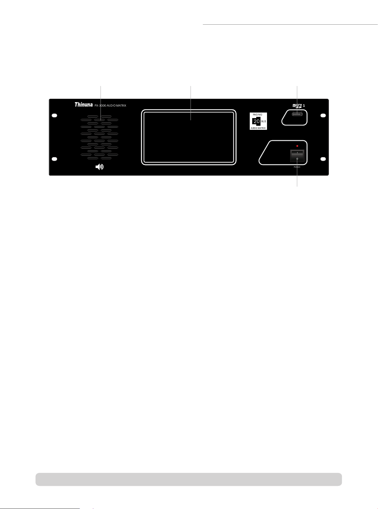
Front Panel of Audio Matrix
1. Monitor Speaker
-Built-in monitor speaker can select and monitor each input or output channel with volume control and mute
switch by touchscreen.
2. Touchscreen
-7" color touchscreen which with a full operating system and real-time status monitoring. The resolution is
800x600, the backlight brightness and screen saver time can be set on the setting many.
3. Micro SD1 (TF1) card slot
-Max 32G, MP3 support any sampling rate Layer3 audio decoding. Micro SD1: for BGM or Built-in timer;
Support FAT16 and FAT32 file system.
4. Power Switch and indicator
-When the matrix power on, the LED on. When the matrix power off, the LED off.
1 2 3
4
Page 4 Version A www.thinuna.com
Audio Matrix Part

Rear Panel of Audio Matrix
1. Ethernet Control Connector
-Through this port, you can connect this unit to PC, ethernet, internet or other control system. And setup the
matrix for system application, monitoring, remote control and so on.
Note: for the detail control command, please contact your supplier.
2. Firmware Upgrade Port
3. Control output port
-This port use to connect the power sequencer, amplifier detector or other equipment which can be controlled.
4. Micro SD2 (TF2) card slot
-Max 32G, MP3 support any sampling rate Layer3 audio decoding. Micro SD2: for internal fire Pre-recorded
message. Support FAT16 and FAT32 file system.
5. Remote Microphone Station Input Port
-Up to 8 pcs remote microphone station can be connected to this matrix. All the 8 remote microphone can be
set as emergency paging microphone or business broadcast microphone.
The priority is EM>RM, when the system has two or more EM or RM, the priority will be sequence by the port
number: Port1>2>3>4>5>6>7>8.
6. Link In and Link Out Port
-Using those two port to link in and link out the master and slaver matrix, Max 32 pcs audio matrix controller
can be linked and up to 256 zones can be supported.
7. External Timer Contact Input Port
-Using this port to connect the external timer contact out and open above external timer audio signal.
8. External Timer Audio Signal Input Port
-Using this port to connect the external timer audio signal.
-Through this prot, you can update the flash firmware to newest function and debug the program.
1 2 3 4567 8 9 10 11 12 13 14 15
16 17 18 19 20 21
Page 5 Version A www.thinuna.com
Audio Matrix Part

9. External Time Input Gain Control Knob.
-To adjust the input gain of external timer. Adjust the input gain to proper level to avoid distortion.
10. External Fire Alarm Input Gain Control Knob
-To adjust the input gain of external fire alarm audio. Adjust the input gain to proper level to avoid distortion.
11. External Fire Alarm Audio Signal Input Port
-Using this port to connect the external fire alarm audio signal.
12. Emergency Paging Contact Output Port
-When the system is doing a fire alarm or emergency paging this port will output a contact closure to activate
other third-party equipment like sound-light alertor, CCTV, etc.
13. 8CH Audio Input Port (BGM Priority)
-RCA stereo input ports for AUX1-8 BGM audio source such as CD, MP3, tuner, iPad, PC etc.
14. 8CH Audio Output Port For Each Zone (Mono, Unbalanced, +-)
-Using those RCA port to connect these audio output to the amplifier, record devices, effect processor, or other
destination as required by the installation of each zone.
15. 8CH Audio Output Port For Each Zone (Mono, Balanced, +-G)
-Using those phoenix port to connect these audio output to the amplifier, record devices, effect processor, or
other destination as required by the installation of each zone.
16. Signal Gnd Connector
-When lots of equipments are connected to this matrix and there is noise in system, please connect this screw
terminal to other units’s GNG, it may reduce or avoid the noise. (Note: this is not the safety ground)
17. AC Power Input Port
-Universal wide voltage switching power supply: 100~240VAC, 50/60Hz: Max output 156W.
18. Volume Controller Override Control Port
-Support 3 wire and 4 wire (require external PSU) volume controller override.
For detailed connections please see page54.
19. Fire Alarm Trigger Input Port
-8 channels of dry contact closure signal from fire control system can be connected to these port. When the
contact closure inputs coming, the microSD2 pre-recorded message or external fire alarm audio will automatic
be page to related zones(by software setting). And the related zones will display“Fire”on the touchscreen to
show now is doing a fire alarm.
20. Amp Link Audio Output Port
-Using this port to connect the 4CH amplifier which also has a amp link port. 4 channels audio signal can be
transmitted by only one twisted pair network cable.
21. Remote Wall Panel Input Port
-0-8 pcs remote wall panel can be connected into each zone. Use the wall panel to select audio source, adjust
volume, local mic/line audio input for each zone.
Page 6 Version A www.thinuna.com
Audio Matrix Part

Audio screen description
The main touchscreen on the matrix display the matrix name, date & time, zone name, audio source and
volume information. On this screen, you can control the select the audio source, set the volume and mute
for each zone.
1. Audio Matrix Name
-The Name can be set by 20 bus assistant PC setup software, please see the PC software part.
2. Date and Time
-Date and time can be set by 20 bus assistant PC setup software, please see the PC software part.
3. Audio Source Manu Button
-Click this button can switch to the “Audio Source”main screen.
4. Task Manu Button
-Click this button can switch to the "Task”main screen.
5. Device Manu Button
-Click this button can switch to the“Device”main screen.
6. Monitor Button
-Click this button can switch to the“Monitor”main screen.
7. Set Manu Button
-Click this button can switch to the“Set”main screen.
1 2 345 6 7
8
9
10
11
12
13
14
Page 7 Version A www.thinuna.com
Audio Matrix Part

11. Volume Value
-Display the current volume value.
12. Volume Fader
-Click this volume fader to change the volume for current zone.
13. Volume Up/Down Button
-Click these two Up/Down button to add or reduce the volume for current zone.
14. Output Volume Indicator
-These LED indicator will show the current output level dynamically.
8. Zone Name
-The zone name can be set by 20 bus assistant PC setup software, please see the PC software part.
9. Mute Button
-Click this button will mute the BGM audio source, click again will cancel the mute function.
10. Audio Source Selection Button
-The button will display current audio source name. Click this button can switch to audio source screen, and
then select the audio source for current zone. The audio source include Aux1-8 on master matrix, Wall Panel
input for each zone, built-in Micro SD1 BGM. Below is the audio source screen.
Page 8 Version A www.thinuna.com
Audio Matrix Part

Task Screen Description
Task screen display all the task which preset by PC setup software.
1. Task Name
-Display the task name. (Note: EXT-Timer has the highest priority in all task. When some task has time conflict, the front
task will has higher priority.)
2. Detailed Task Information
-Display the detailed task information. The Task information includes: Timer type, source, play mode, play count, play
start time and finish time, week. The audio source for task is Line input 1-8 of the matrix and the built-in Micro SD1(when
SD1 is set to be timer source.) All the task should be set by the PC setup software.
(For example: the morning reading task shows that is a internal-timer, the audio source is the line input of the matrix, the
start time is 06:50, the finish time is 06:51, run from monday to friday.
3. Task Status Button
-Display the current task status and you can click this button to change the task status.
4. Page Up/Down Button
-Click this button can check all the task.
12 3 4
Page 9 Version A www.thinuna.com
Audio Matrix Part

Device Screen Description
Device screen display all the devices information in the PA system.
1. Different Device Selection Button
-Click those button will switch to audio matrix, remote microphone station or wall panel screen.
2. Force Check Button
-Click this button can force check all the on line system devices.
3. Page button
-Click this button can switch to another page screen.
4. Device Information Screen
-Display all the device information in a group.
4
3
2
1
Page 10 Version A www.thinuna.com
Audio Matrix Part

Monitoring Screen Description
On this monitor screen, you can choose to monitor all the system audio signal. Audio signal includes: the
20bus audio signal(which from master matrix: AUX1-8, SD1, RM1-8, SD2 built-in fire alarm, external
timing, external fire alarm), 8 channels zone output audio signal and the wall panel audio input from each
zone.
1. Page button
-Click to choose the audio source screen which you want
to monitor.
2. Audio Source Information Screen
-Display all the audio source information in a system.
3. Stop Button
-Click this button to stop monitoring.
4. Monitor Volume Value
-Display the current monitor volume value.
5. Volume Fader and Volume Up/Down button
-Push the fader or click Up/Down button to add or reduce volume for current monitor channel .
6. Mute Button For Monitor Speaker
-Click this button will mute the monitor speaker, click again will cancel the mute function.
23
1
4
5
6
Page 11 Version A www.thinuna.com
Audio Matrix Part

Setting Screen Description
On setting screen, you can change IP address, set ID, change the language, check the firmware
version, set all the input gain, output EQ, play micro SD1 music etc.
1. Connect Button
-Click to set IP address, ID, choose the language and see the firmware version. When finished the
setting, please click the save button to save the changes.
2. Input Gain Button
-Click this button to set input gain for all input audio signal (See the picture below).
1 2 34
5
6
7 8 9
Page 12 Version A www.thinuna.com
Audio Matrix Part

3. Output EQ Button
-Click this button to set 8 channels output EQ of the matrix (includes volume, treble and bass).
4. SD Play Button
-Click this button to switch to the SD card audio playing operation (see next page to know the
detailed).
5. IP Address Bar
-IP address of matrix can be seen and changed here. To connect your setting PC, you need to set to
correct IP address.
6. IDBar
-ID address of matrix can be seen and changed here. Note: ID0 is the master matrix and the
ID1~ID31 is the slaver matrix 1~31. All the matrix should be has a different ID. When the matrix is set
to ID 1~31(it means that it's a slaver matrix), all the input of it can no be use.
7. Language Button
-Click to change the different language for the touchscreen.
8. Firmware Version
-It show the current firmware version of the touchscreen.
9. Save Button
-When finished the setting, please click the save button to save the changes.
Page 13 Version A www.thinuna.com
Audio Matrix Part

SD Card Playing Screen Description
On this SD playing screen, you can operate all the music playing function (on the Micro SD1 on the front
of the matrix).
1. Micro SD1 Input Gain Button
-Push the fader or click Up/Down button to add or reduce volume for SD1 playing volume.
2. The Player Status
-It shows the player status. The song name can be read here.
3. Playing Mode Status
-It shows the current play mode your choose. When the mode set to be“Play One”or “Repeat One”, the
“Next”button can not be click and click the “PREV”will play again the song.
4. Player Operation Button
PREV PAUSE STOP NEXT
5. Back Button
Click this button to back to previous folder.
6. Play Mode Select Button
Play One Repeat One Order Play Random Repeat All Play
-Note: When only one song in a folder, just the “Play One”and “Repeat One” can be selected.
when there are many songs in a folder, click the “Play” button to order play all the songs.
1
4
23
6
5
7 8 9
Page 14 Version A www.thinuna.com
Audio Matrix Part

7. Current Folder Name
-It shows the current folder name.
8. Folder Information
-It shows all the folder and files in current Folder.
9. Page Up/Down Button
Page Up Page Down Back to top
Page 15 Version A www.thinuna.com
Audio Matrix Part

Front Panel of Remote Microphone Station
The microphone station has a convenient touchscreen interactive interface. It can be set as business
microphone station or emergency paging microphone station.
1. Gooseneck microphone input port
-Insert condenser microphone and supply 24VDC phantom power.
2. Touchscreen
-7-inch color touchscreen with all operating and real-time status monitoring. The touchscreen has real-time
audio signal output indicator. The brightness and saver time of touchscreen are adjustable.
3. Talk/Paing LED Indicator
-When doing a normal paging or emergency paging, the LED turn red; when paging finished, the LED turn
green to show the power status.
4.“TALK”TALK button
-Press this button to talk and press again to cancel (Push on / Push off mode).
Pressing this button to talk and release this button to cancel (PTT mode: Push-to-talk)
Each corresponding zone will display red or yellow paging status indicating that the zone is receiving an
announcement.
TALK
1 2
3 4
Page 16 Version A www.thinuna.com
Remote Microphone Station Part

Rear Panel of Remote Microphone Station
The remote microphone has an aux input and a build-in Micro SD card. So it not only a paging
microphone station, but also it can play external audio input or build-in SD card audio files to any zone
you want. Selecting audio source and then press talk button to play audio. When finishing playing, press
talk button again to cancel. (Note: When playing external aux input or micro SD card, you can switch the
source to gooseneck microphone again).
1.
-When the microphone power on, the LED around talk button on. When power off, the power LED off.
2. External Power Input Port
-External DC24V power input port (Note: the RJ-45 port will supply the 24VDC power from the matrix. If the
long distance cabling cause the voltage down, you need to use this Ext. power supply).
3. External Aux Input Port
-Connect external audio source here, like PC, Mobile, CD or iPad etc.
4. Micro SD(TF) Card Slot
-Plug your micro SD(TF) card here, the audio format support mp3, wav etc. The card max support 32G and
FAT16 & FAT32 file system.
5. Connect To The Master Matrix
-Up to 8 pcs remote microphone station can be connected to the master audio matrix. All remote
microphones can be set as emergency paging microphone or business broadcast microphone. The priority is
EM>RM, when the system has two or more EM or RM, the priority will be sequence by the port number:
Port1>2>3>4>5>6>7>8. The cable should be cat 5 or better twisted pair. (The RJ45 should be 568B type).
Communications protocol: RS-485; Communication distance: max 1000 meters; Power: 24VDC; Audio: mono.
6. Reserved COM Port
-Reseved com port for future use.
Power Switch
1 2 3456
Page 17 Version A www.thinuna.com
Remote Microphone Station Part
This manual suits for next models
2
Table of contents
Other Thinuna Recording Equipment manuals


