Thomas&Betts Elastimold K656DR Manual

IS---0366
IS---K656DR
September 2010
Page 1 of 3
Installation/Operating Instructions
K656DR
Deadbreak Insulated Cap with Test Point
CONTENTS: Insulated Cap, Lubricant (Do Not Substitute), Stud (if applicable), Installation Instructions.
The K656DR is designed for insulating, shielding and watersealing any ELASTIMOLD 15kV class (8.3kV phase--to--ground) and
25kV class (15.2 kV phase--to--ground) 600 amp deadbreak bushing interface.
DANGER
All apparatus must be de--energized during installation
or removal of part(s). For loadbreak products follow
operating instructions. All deadbreak connectors must
be de--energized before operating. All 200A deadbreak
connectors must be mechanically secured with bails
when connected.
All apparatus must be installed and operated in
accordance with individual user, local, and national
work rules. These instructions do not attempt to provide
for every possible contingency.
Do not touch or move energized products.
Excess distortion of the assembled product may result
in its failure.
Inspect parts for damage, rating and compatibility with
mating parts.
This product should be installed only by competent
personnel trained in good safety practices involving
high voltage electrical equipment. These instructions
are not intended as a substitute for adequate training or
experience in such safety practices.
Failure to follow these instructions will result in damage
to the product and serious or fatal injury.
If this product is supplied with a protective shipping
cover(s), remove this shipping cover(s) and replace with
the appropriate HV insulated cap(s) or connector(s)
before submerging or energizing the circuit.
FOR MORE INFORMATION ON PARTS, INSTALLATION RATINGS AND COMPATIBILITY, CALL THE NEAREST ELASTIMOLD OFFICE.
IMPORTANT
1. Check contents of package to ensure they are complete
and undamaged.
2. Check all components to ensure proper fit with cable
and/or mating products.
3. Read entire installation instructions before starting.
4. Have all required tools at hand and maintain cleanliness
throughout the procedure.
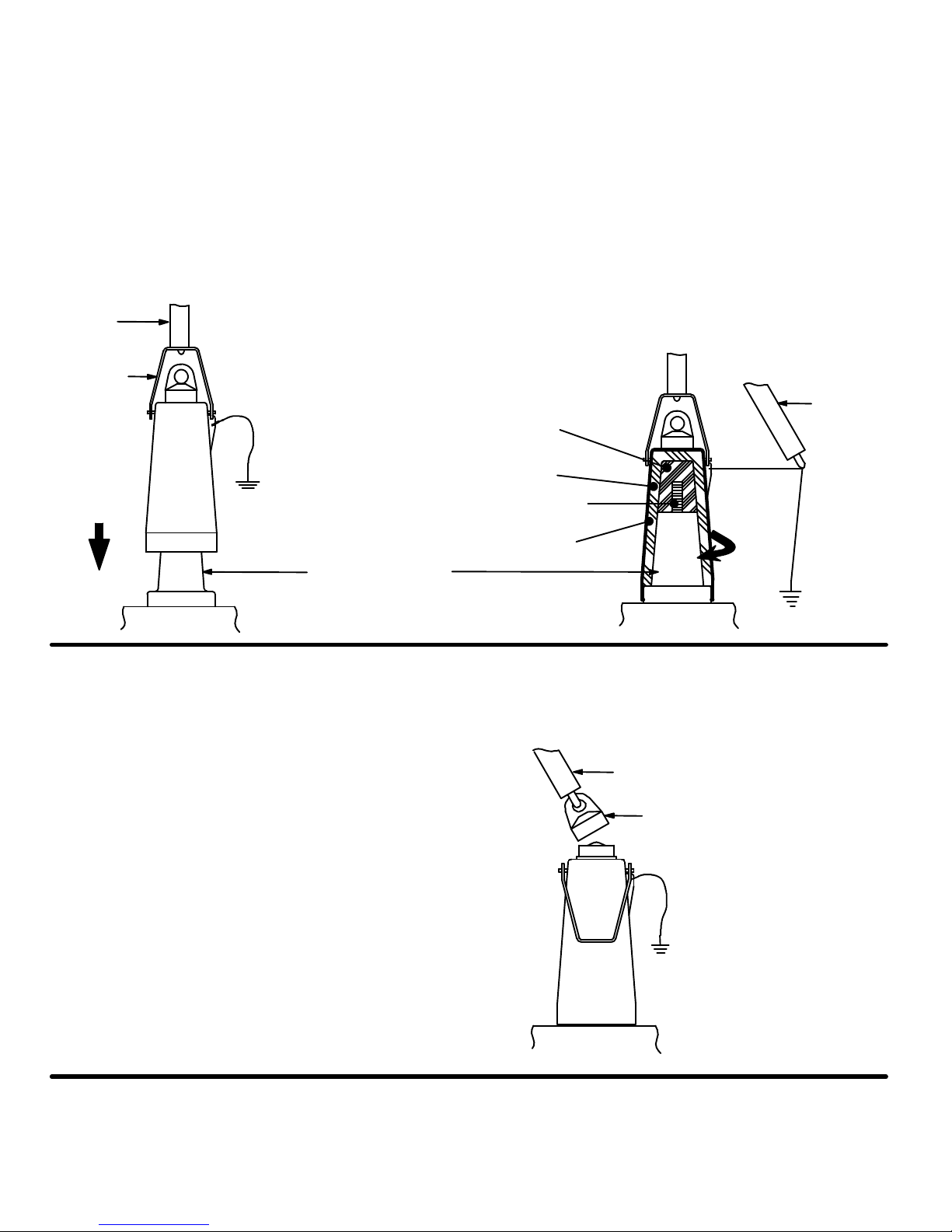
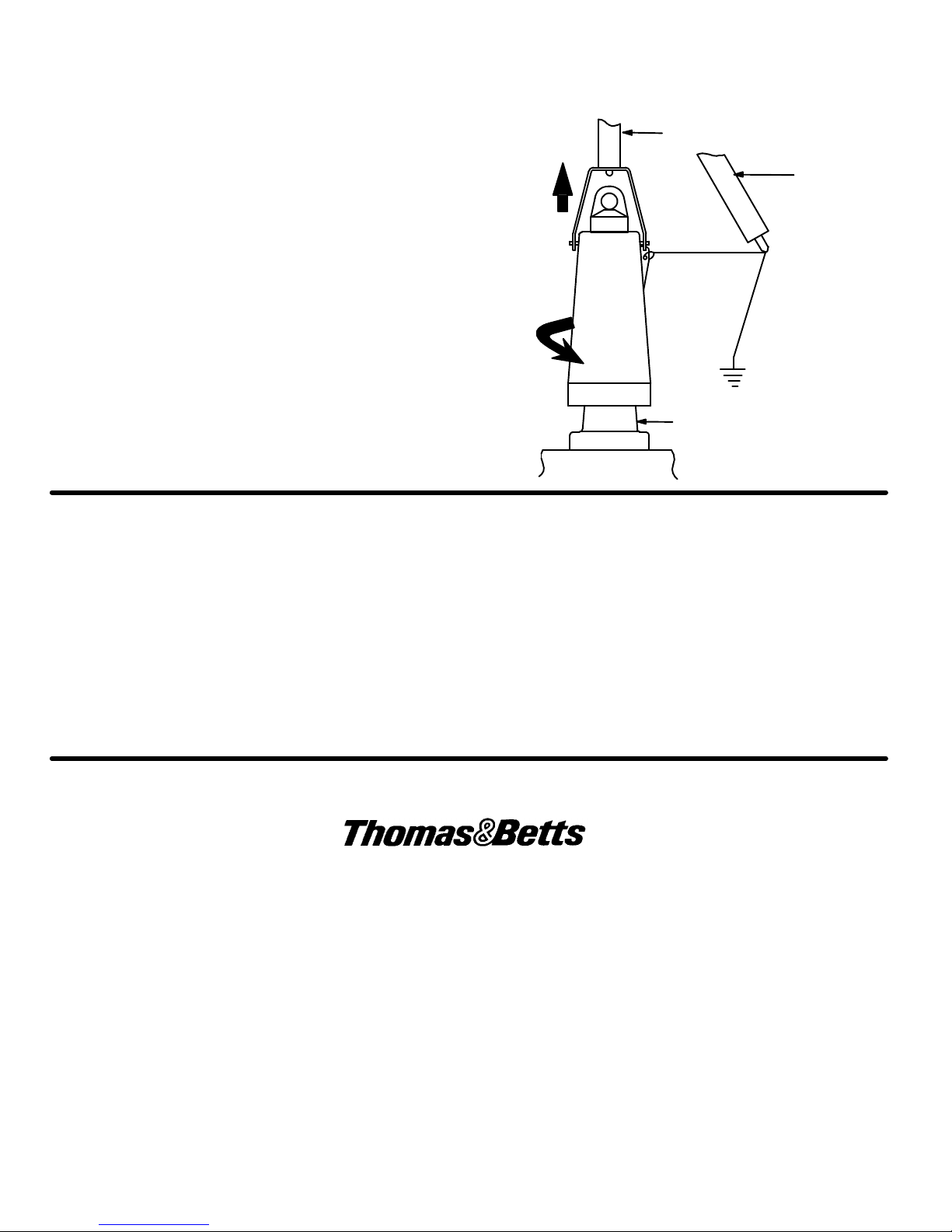
Installing The Insulating Cap
STEP 1
Insert a length of No. 14 AWG ( 2.5mm2) copper wire (or
equivalent) through the grounding eye of the insulated cap.
Make a small loop and twist tight, taking care not to damage the
grounding eye. Connect free end of grounding wire to the
system ground using a suitable connector. Length of grounding
wire should be sufficient for the distance from the grounding
point to the grounding eye of the insulated cap when installed.
If the bushing is not equipped with a stud, hand assemble the
stud supplied into the insulated cap. If the bushing is equipped
with a stud, discard the stud supplied.
No. 14 Copper
Grounding Wire
To Ground
Stud (Where Applicable)
STEP 2
In new installations, where the bushing is known to be
de--energized, thoroughly wipe the bushing interface and the
insulated cap interface clean of all contaminants. Lubricate
above surfaces with the supplied lubricant or Elastimold
approved lubricant. On circuits previously energized, clean and
lubricate only the interface of the insulated cap.
Clean and Lubricate
Bushing Interface
Apparatus
IS---0366
IS---K656DR
September 2010
Printed in U.S.A.
8155 T&B Boulevard, Memphis, Tennessee 38125
(800) 888--0211 Fax: (800) 888--0690

IS---0366
September 2010
Page 2 of 3
STEP 3
During installation of the insulated cap, the grounding wire will be wrapped around the body of the insulated cap. A second
hotstick will be required to control the tension and position of the grounding wire. The wire should be wrapped loosely about the
center of the insulated cap.
Attach the first hotstick tool to the insulated cap pulling ring and push receptacle onto bushing interface as far as it will go. With
the second hotstick, engage grounding wire and establish slight tension (see illustration). With first hotstick, while pushing
against the bushing interface, twist clockwise until the threads between bushing and insulated cap engage; continue turning
without pushing until resistance is felt. DO NOT OVERTIGHTEN.
Push
Hotstick
Pulling Ring
Bushing Interface
Apparatus
2nd Hotstick
Apparatus
Rotate
Stud
Conductive Insert
Insulation
Conductive Jacket
Removing The Insulated Cap
WARNING: DO NOT DISCONNECT WHILE ENERGIZED.
STEP 1
To determine if the system is energized, remove the voltage
detection point cap with a hotstick. When removing cap,
PEEL OFF AT AN ANGLE rather than pulling directly in line
with the voltage detection assembly. Using an appropriate
high impedance testing device, check the voltage detection
point for indication of circuit condition. Replace the voltage
detection point cap.
CAUTION: The voltage detection point is a capacitance
device; it is not directly connected to the conductor. It
requires the use of specially designed instruments. DO NOT
USE CONVENTIONAL VOLTAGE MEASURING
EQUIPMENT: NO INDICATION WILL BE OBTAINED. FOR
CORRECT TEST POINT VOLTAGE INDICATION, THE
INSULATED CAP HOUSING MUST BE GROUNDED.
Hotstick
Apparatus
Remove Cap with Hotstick
Replace Cap After Testing

IS---0366
September 2010
Page 3 of 3
STEP 2
After the circuit is known to be de--energized, securely fasten
a hotstick to the pulling ring. Without exerting any pulling
force, rotate the receptacle counter--clockwise eight or nine
turns. With a second hotstick tool, control the unwound
ground wire so that the wire will not interfere with adjacent
devices or entangle itself with the first hot stick tool. Then
exert pulling force to remove the insulated cap from the
bushing interface.
Hotstick
Pull
Bushing Interface
Apparatus
2nd Hotstick
VOLTAGE TEST
The ELASTIMOLD deadbreak elbow connector is equipped with an integral capacitance test point that can be used to
establish whether or not the circuit is energized. When using the test point, complete the following steps:
1. Remove test point cap with a hotstick. When removing cap, PEEL OFF AT AN ANGLE rather than pulling directly in line
with the test point assembly.
2. WARNING: THE VOLTAGE TEST POINT IS A CAPACITANCE DEVICE, IT IS NOT DIRECTLY CONNECTED TO THE
CONDUCTOR. Do not use conventional voltage measuring equipment. Follow the manufacturer’s directions for the
meter that is used. Test with a suitable sensing device, made for use with separable connectors manufactured with
capacitive test points, to determine if cable is energized. Contamination, moisture, dirt, etc. around the test point or use
of the wrong measuring equipment can provide a false “no voltage” indication on an energized elbow. To prevent
serious or fatal injury treat the elbow as energized until the “no voltage” test point indication is confirmed by other means.
3. After voltage detection has been made, clean and lubricate the inside surface of the cap with silicone grease and
replace it on the test point.
8155 T&B Boulevard, Memphis, Tennessee 38125
(800) 888--0211 Fax: (800) 888--0690
Table of contents
Other Thomas&Betts Cables And Connectors manuals