2
System ID - System Segregation
The system ID provides a mechanism for segregation of two or more systems that are in close physical proximity,
as summarised previously.
System Commissioning and DLP Support
Commissioning of Nexus® RF systems by a Thomas & Betts Nexus technician and support throughout a standard
12 month defects liability period (DLP) are included in system quotations. This service is usually shown as a
separate quotation line and should be ordered at the time of system purchase or no later than completion of
installation.
Thomas&BettscommissioningandDLPsupportfurthersimpliesthetaskoftheinstallingcontractorandensures
thattheendusertakesdeliveryofasystemthatperformstothebestofitsability.Thecontractorisresponsiblefor
providingsite-specicinformation,aswouldbethecaseforpreparationofastandardemergencylightinglogbook.
Guidance on the requirements will be made available by Thomas & Betts.
Commissioningmaybeundertakenremotefromthesite,particularlyinthecaseofruralorremotelocations,in
which case it is a requirement that remote access is available through a reliable broadband internet connection;
Thomas & Betts will provide a wireless broadband modem for the duration of the DLP and may call on the
customer’s on-site maintenance staff to connect the modem or reset from time to time if required. Alternatively,
remote access may be made available by the end user via a WAN or VPN connection to the site.
DLP support includes testing at 6 and 12 month intervals following completion of commissioning and repairs which
may be required following testing.
The Four Steps to a Nexus RF System
Nexus RF System Design
Step 1 - Review the site plans and determine the
tting requirements
It is important that the site plans are reviewed and
thetotalttingnumbersandtypesareestablishedas
earlyaspossible.Atthispointanynon-standardtting
requirementsneedtobehighlightedtothekeyaccount
manager.
Step 2 - Planning the number and location of the
Routers
The number of Routers and their optimal locations
dependonthenumberofttingswithinthebuildingand
theconcentrationofthesettingswithincertainareas.
The rules for determining the number of Routers and
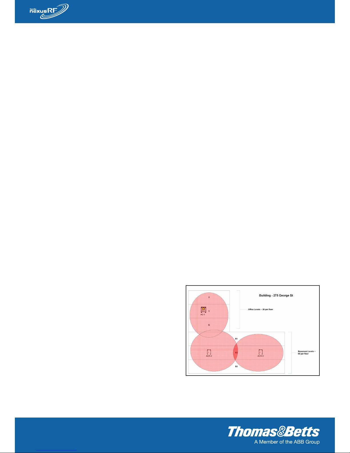
Figure 1 - Shows a typical ofce building with 3 Routers
optimally located to pick up the site’s 270 ttings. The shaded
areas are representative of how it is envisaged the mesh
networks will form.