The 68P-DV-KIT will work with either conduit
arrangement.
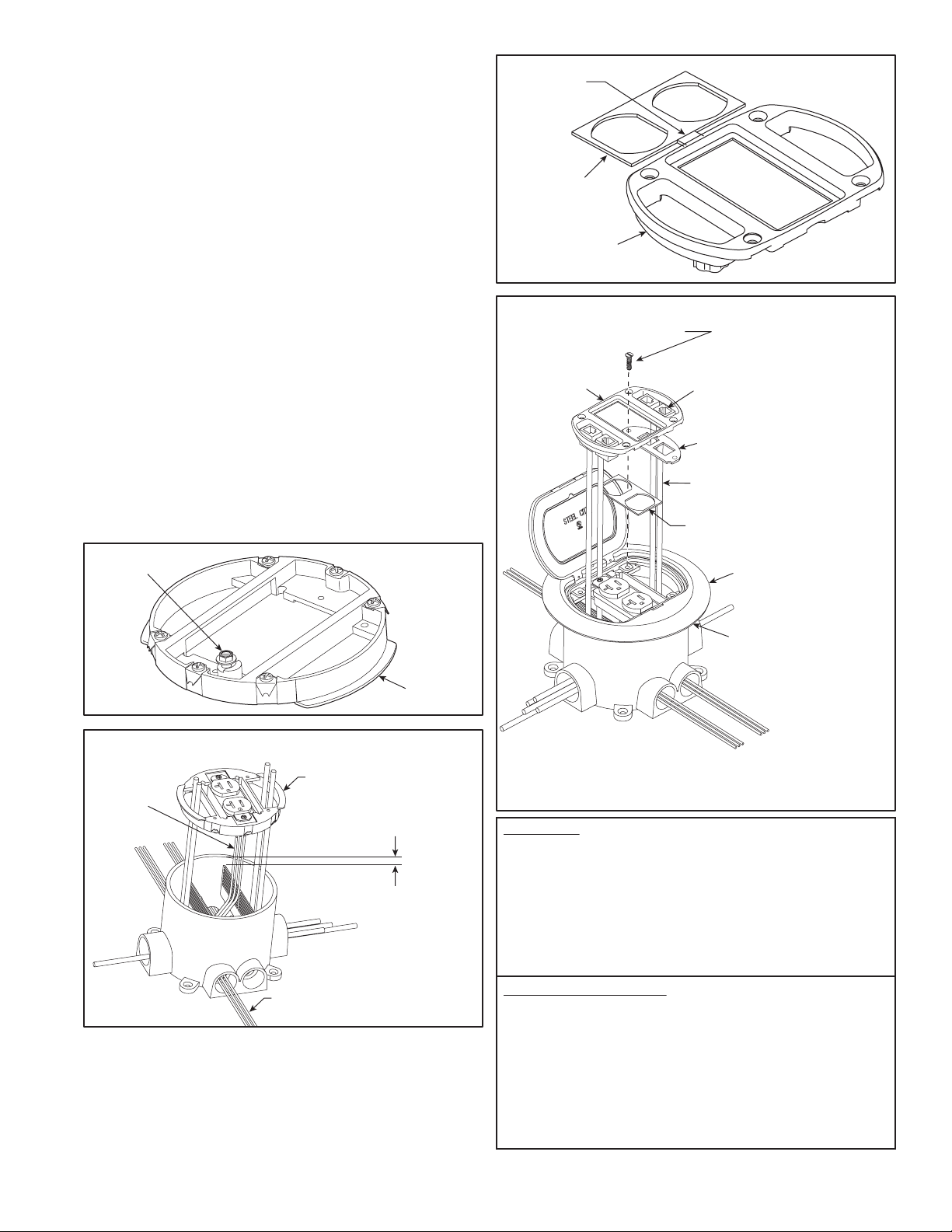
FIGURE 6
Mounting Ring
Grounding Lug
FIGURE 7
Mounting Ring
"THROUGH" power wires
Top of Divider 1/2" below
top surface of Floor Box.
Install Duplex
to power
wires
FIGURE 8
Face Plate
Trim Clean
with Utlily Knife
Duplex Cover
FIGURE 9
Secure (4) screws through faceplate,
cover and into mounting ring.
Faceplate
Duplex Cover
(Discard if using GFI)
Apply Caulk or Sealant
under Flange on Wood
or Tile Floors
Connect Data Cable to
Data Jacks
*
Data Plates
(See NOTE Below)
Cover Assembly
Snap Keystone Data Jacks
in bottom of Faceplate
*NOTE: Keystone Data Plates come standard on the
68P-DV-KIT. Other style Data Plates are available from T&B and
and can be ordered separately.
6) Re-insert divider assembly into oor box. Pull power wires
up through center of oor box. Pull non-used or (through)
wires over ramp and into conduit openings on opposite side
of box. Install duplex receptacle device onto mounting ring
per device instructions and make electrical connections in
accordance with national and local electrical codes. A
grounding lug is provided on the underside of mounting
ring. Terminate grounding wire to grounding lug when
required by device installation instructions or national or
local codes (see Figure 6 and 7).
7) Verify divider assembly is aligned with conduit direction.
The divider assembly can be rotated a few degrees in either
direction to align with conduit openings. Align mounting ring
vertical walls with divider vertical walls and push (install)
mounting ring onto top of the oor box (see Figure 7).
8) On wood or tile oors, apply caulk or sealant to the
underside of carpet ange to block water entry (see Figure 9).
9) Place cover assembly onto top of mounting ring. Pull data
cable up through side openings and install to data jacks per
manufacturer’s instructions (see Figure 9).
10)
Trim duplex cover from face plate using utility knife. Place
duplex cover on top of duplex receptacle before installing
face plate (see Figures 8 and 9).
11) Snap keystone jacks into data plates (see Figure 9).
12)
Assemble faceplate onto cover using four No. 8 x 3/4" long
at head screws (see Figure 9).
© 2008 Thomas & Betts. All Rights Reserved. TA02485 C
page 2 of 2
WARRANTY: Thomas & Betts sells this product with the
understanding that the user will perform all necessary tests to
determine the suitability of this product for the user's intended
application. Thomas & Betts warrants that this product will be free
from defects in materials and workmanship for a period of two (2)
years following the date of purchase. Upon prompt notication of any
warranted defect, Thomas & Betts will, at its option, repair or replace
the defective product or refund the purchase price. Proof of
purchase is required. Misuse or unauthorized modication of the
product voids all warranties.
Limitations and Exclusions: THE ABOVE WARRANTY IS THE
SOLE WARRANTY CONCERNING THIS PRODUCT, AND IS IN
LIEU OF ALL OTHER WARRANTIES EXPRESS OR IMPLIED,
INCLUDING BUT NOT LIMITED TO ANY IMPLIED WARRANTY OF
MERCHANTABILITY OR FITNESS FOR A PARTICULAR
PURPOSE, WHICH ARE SPECIFICALLY DISCLAIMED. LIABILITY
FOR BREACH OF THE ABOVE WARRANTY IS LIMITED TO COST
OF REPAIR OR REPLACEMENT OF THE PRODUCT, AND UNDER
NO CIRCUMSTANCES WILL THOMAS & BETTS BE LIABLE FOR
ANY INDIRECT, SPECIAL, INCIDENTAL OR CONSEQUENTIAL
DAMAGES.
Thomas & Betts Corporation
Memphis, Tennessee
www.tnb.com


