Thomas&Betts Elastimold 274FT User manual

IS---0797
IS---274FT(1)
January 2010
Page 1 of 4
Operating Instructions
274FT(1)
Feed--Thru/Grounding Device
CONTENTS: Feed--thru body complete with mounting hardware, Lubricant, Operating Instructions.
The feed thru provides interconnected apparatus interfaces for Elastimold 25kV class (15.2kV phase--to--ground and 26.3kV
phase--to--phase) loadbreak connections and can be used for the following functions:
A. A junction point. B. A grounding point.
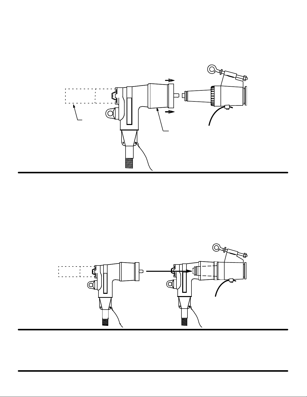
To use the feed--thru as a junction point, follow steps 1 to 5 and 6A and 7A.
To use the feed--thru as a grounding point, follow steps 1 to 5 and 6B to 9B.
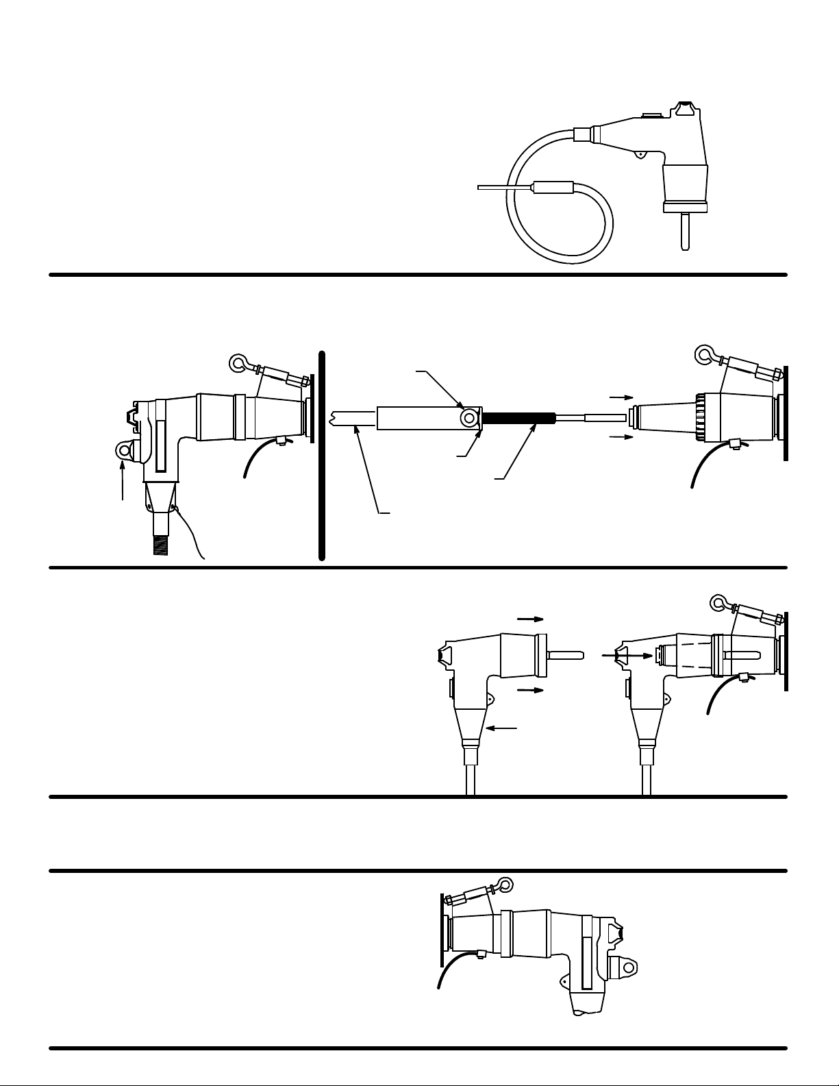
A yellow band provides indication of full elbow seating and also provides vents for improved switching performance. This
product is identified by a yellow ID washer attached to the eyebolt.
DANGER
All apparatus must be de--energized during installation
or removal of part(s) except for test point caps and
indicators that can be installed and operated
energized.
After installation loadbreak products can be operated
energized per operating instructions. All deadbreak
connectors must be de--energized before operating.
All apparatus must be installed and operated in
accordance with individual user, local, and national
work rules. These instructions do not attempt to
provide for every possible contingency.
Do not touch or move energized products.
“Loadbreak connectors must be operated with a full
insulated “hotstick” type live--line tool.” Consult the
company’s safe work practices for the required
live--line tool length.
Excess distortion of the assembled product may result
in its failure.
Inspect parts for damage, rating and compatibility with
mating parts.
This product should be installed only by competent
personnel trained in good safety practices involving
high voltage electrical equipment. These instructions
are not intended as a substitute for adequate training or
experience in such safety practices.
Failure to follow these instructions will result in
damage to the product and serious or fatal injury.
If this product is supplied with a protective shipping
cover(s), remove this shipping cover(s) and replace
with the appropriate HV insulated cap(s) or
connector(s) before submerging or energizing the
circuit.
FOR MORE INFORMATION ON PARTS, INSTALLATION RATINGS AND COMPATIBILITY, CALL THE NEAREST ELASTIMOLD OFFICE.
IMPORTANT
1. Check contents of package to ensure they are complete
and undamaged.
2. Check all components to ensure proper fit with cable
and/or mating products.
3. Read entire installation instructions before starting.
4. Have all required tools at hand and maintain cleanliness
throughout the procedure.
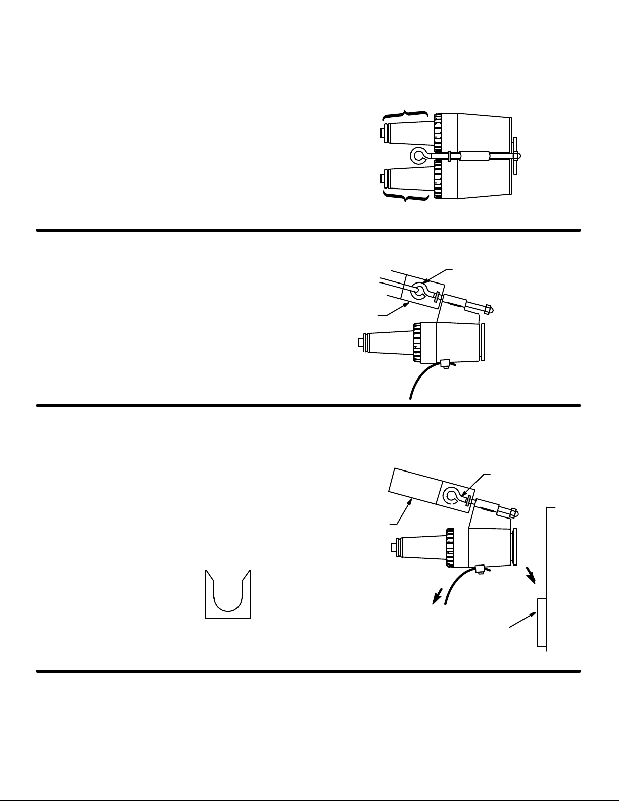
STEP 1
Grounding-- Insert ground lead into the grounding lug
provided on the mounting hardware and tighten lug. Ground
lead should be No. 14 copper wire or equivalent. Connect
the opposite end of the lead to ground, leaving enough slack
to operate with a hotstick.
IS---0797
IS---274FT(1)
January 2010
Printed in U.S.A.
8155 T&B Boulevard, Memphis, Tennessee 38125
(800) 888--0211 Fax: (800) 888--0690
Ground Lug
No. 14 Copper Wire
To Ground
Yellow Seating Indicator
and Vent Ring
Yellow ID Washer

IS---0797
January 2010
Page 2 of 4
STEP 2
Remove the protective caps from the bushings of the
feed--thru.
PROTECTIVE CAPS MUST NOT BE ON THE BUSHINGS
OF THE FEED--THRU WHEN THE FEED--THRU IS
BEING USED. When the feed--thru is not in use, the
protective caps should be placed on the bushings of the
feed--thru to protect them from dirt and other contaminants.
Clean the bushing surfaces and lubricate them with the
lubricant supplied. DO NOT SUBSTITUTE. Other
lubricants may be harmful to this product and its mating
product(s).
Clean &
Lubricate
Clean &
Lubricate
STEP 3
Attach feed--thru eye firmly to hotstick. Eye
Hotstick
STEP 4
Using a hotstick, slide feed--thru onto parking stand. Unlock
hotstick and back off, to allow space for eyebolt to be
tightened. Tighten eyebolt by rotating hotstick clockwise
until snug. DO NOT OVERTIGHTEN. Release hotstick.
FRONT VIEW
Parking
Strand
Eyebolt
Hotstick
Parking
Stand
To Ground
SIDE VIEW

IS---0797
January 2010
Page 3 of 4
STEP 5
CAUTION: Check that ground lead is connected between feed--thru lug and ground before assembling elbow. Do not
attempt to attach ground lead after elbow is assembled.
Remove one loadbreak elbow from its apparatus loadbreak bushing plug following the applicable loadbreak operating
instructions (IS-- 273,274LR). Using a hotstick, firmly attached to the elbow, insert the pin contact of the loadbreak elbow into
one of the feed--thru bushings, approximately 2”. Immediately push the elbow home with a fast, firm straight motion which will
engage the internal lock on the mating interfaces. Release hotstick.
Elbow
Hotstick
FOR JUNCTION POINT APPLICATION FOLLOW STEPS 6A AND 7A
STEP 6A
Remove the second loadbreak elbow, following the applicable LOADBREAK operating instructions (IS--273/274LR). Using a
hotstick, firmly attached to the elbow, insert the pin contact of the loadbreak elbow into the remaining feed--thru bushing
approximately 2”. Immediately push the elbow home with a fast, firm straight motion which will engage the internal lock on the
mating interfaces. Release hotstick.
STEP 7A
When it is desired to reconnect the elbow(s) to the apparatus bushing(s), first make certain no faults exist on the system. To
return the loadbreak elbow to the apparatus bushing, reverse the operational sequence, following the applicable
loadbreak--loadmake operating instructions.

IS---0797
January 2010
Page 4 of 4
FOR GROUNDING POINT APPLICATION FOLLOW STEPS 6B TO 9B
STEP 6B
Connect lead on ELASTIMOLD 370GLR grounding elbowto
ground.
CAUTION: Do not attempt to connect the ground lead to
ground after assembling the grounding elbow on the
bushing. If bushing is energized contact with an ungrounded
lead will cause serious or fatal injury from electric shock.
IMPORTANT: Do not insert grounding elbow into
feed--thru unless circuit has been tested ”dead”.
Grounding Elbow
STEP 7B
To test ”dead” use the capacitive test point on the 274LR elbow or using a 370TR test rod, attach the test rod eye firmly to the
hotstick. Insert the test rod into the second plug of the feed--thru. Check the test rod disc for voltage. The hotstick eye and disc of
the test rod are not insulated; be careful to keep them clear from ground until tested ”de--energized”.
Hotstick
370TR
Test Rod
Test Rod
Disc
Operating
Eye
Test
Point
1. 2.
STEP 8B
After the circuit has been tested ”dead” remove the test rod
and, using the hotstick, immediately insert the grounding
elbow.
Grounding Elbow
STEP 9B
When it is desired to reconnect the elbow to the apparatus bushing, first make certain no faults exist on the system to return the
loadbreak elbow to the apparatus bushing. To remove the grounding elbow reverse the operational sequence following the
applicable loadbreak--loadmake operating instructions.
STEP 10 SEATING INDICATION
Complete assembly of an insulated cap or elbow is indicated
by no portion of the yellow band being visible when viewed
from the side.
This manual suits for next models
1
Table of contents
Other Thomas&Betts Industrial Equipment manuals