Service manual of MT31AS
Explanation .......................................................................................................................................1
1. Important Information ..................................................................................................................2
1.1. Important Safety Instructions ....................................................................................................2
2. Product Specification ....................................................................................................................4
2.1. Features .....................................................................................................................................4
2.2. USB multimedia playback format...............................................................................................5
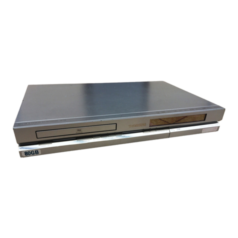
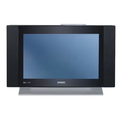
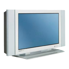
2. The physical picture of 28M1300..................................................................................................5
3. The Exploded view of 28M1300....................................................................................................7
4. The Schematic diagram of Main board .........................................................................................7
5. The Test Guides Of Main Board.....................................................................................................7
5.1. Power Unit .................................................................................................................................9
5.2. Back light driver units...............................................................................................................10
5.3. Decode and I/O Units...............................................................................................................11
5.3.1. The flow of low voltage power supply ..................................................................................11
5.3.2 Small signal process ...............................................................................................................14
5.3.3. Control BUS ...........................................................................................................................15
5.4. Module Circuits Test.................................................................................................................16
5.4.1. The audio power amplifier....................................................................................................16
6. Troubleshooting Flow Chart........................................................................................................17
6.1. Green Power LED does not turn on. ........................................................................................17
6.2. Abnormal display .....................................................................................................................18
Attachment 1: Block diagram
Attachment 2: The Schematic diagram of Main board


