THOMSON CHASSIS MT62L User manual

Service Manual
CHASSIS MT62L
Contents
1. Product Specification………………………..……………………...…….…….2
2. Test and Alignment………………….………………………………...………..3
3. Block Diagram………………………………….…….. .......................……..22
4. MB Schematic Diagram…………………………….......................……….23
5. PSU Schematic Diagram..........................................................................36
6. Exploded View
19HS3244................................................................................................38
26C35H....................................................................................................39
32C35H....................................................................................................41
40C35H....................................................................................................42

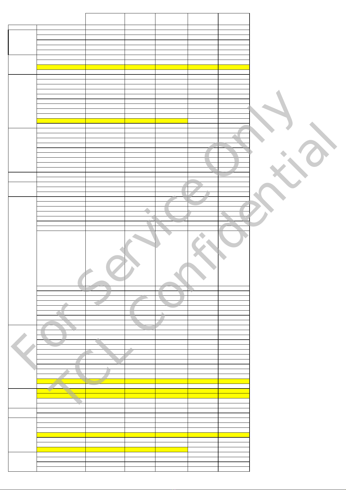
19HS3244 22HS3244 26C35H 32C35H 40C35F
Picture
GoingPriceEuroatIntro.
TargetVolume(K)
Introdate/month/qtr. Mar.2010 Mar.2010 Mar.2010 Mar.2010 Mar.2010
ProjectStartdate
KeyDistrubutionChannel/s MM,BG,CH,TS MM,BG,CH,TS MM,BG,CH,TS MM,BG,CH,TS MM,BG,CH,TS
TypeClassification SmallScreen SmallScreen SmallScreen SmallScreen LargeScreen
Sizes 19W 22W 26W 32W 40W
Chassisplatfrom MT62L MT62L MT62L MT62L MT62L
Styling F11 F11 F10 F10 F10
PanelType Classic Classic Classic Classic Classic
BLU CCFL CCFL CCFL CCFL CCFL
Resoulution HD HD HD HD FHD
60Hz/120Hz 60Hz 60Hz 60Hz 60Hz 60Hz
ContrastRatio Suppliertospecify Suppliertospecify Suppliertospecify Suppliertospecify Suppliertospecify
Brightness 400nitsorLess 400nitsorLess 400nitsorLess 400nitsorLess 400nitsorLess
ViewAngle Suppliertospecify Suppliertospecify Suppliertospecify Suppliertospecify Suppliertospecify
Antireflexcoatedglass Suppliertospecify Suppliertospecify Suppliertospecify Suppliertospecify Suppliertospecify
DynamicContrast Yes Yes Yes Yes Yes
Lightsensor No No No Yes Yes
BacklightControl Yes Yes Yes Yes Yes
Anlogue/Digital Digital Digital Digital Digital Digital
MPEG2 Yes Yes Yes Yes Yes
MPEG4Yes Yes Yes Yes Yes
DVB‐T/T2/Cfrontend DVB‐T DVB‐T DVB‐T DVB‐T DVB‐T
MHEG1.06 No No No No No
CI(PCMCIA) Yes Yes Yes Yes Yes
CI+ No No No No No
OADNo No No No No
DVBTCVBSoutput Yes Yes Yes Yes Yes
CombFilter 3D 3D 3D 3D 3D
De‐interlacing 3D 3D 3D 3D 3D
SoundOutput 2X3W 2X3W 2X3W 2X5W 2X5W
NoofSpeakers 22222
Mono/Stereo/BBE Stereo Stereo Stereo Stereo Stereo
MEMC No No No No No
TeletextTeletext1.5 Teletext1.5 Teletext1.5 Teletext1.5 Teletext1.5
Noofpages(Teletext) 100‐1000p 100‐1000p 100‐1000p 100‐1000p 100‐1000p
CloseCaption No No No No No
HDVideoPlayback No No No No No
MP3Playback No No No No No
Photoviewer Yes Yes Yes Yes Yes
OSDLanguages
German,Italy,Czech,
Croatian,Danish,
Hungarian,Dutch,
Norwegian,Polish,
Portuguese,Romanian,
Slovak,Slovenian,
Serbian,Finnish,
Swedish,Turkish,Greek,
Bulgarian,
Russian,Latvian,Lithuani
an,Estonian,
French,German,
Italy,Czech,
Croatian,Danish,
Hungarian,Dutch,
Norwegian,Polish,
Portuguese,
Romanian,Slovak,
Slovenian,Serbian,
Finnish,Swedish,
Turkish,Greek,
Bulgarian,
French,German,
Italy,Czech,
Croatian,Danish,
Hungarian,Dutch,
Norwegian,Polish,
Portuguese,
Romanian,Slovak,
Slovenian,Serbian,
Finnish,Swedish,
Turkish,Greek,
Bulgarian,
French,German,
Italy,Czech,
Croatian,Danish,
Hungarian,Dutch,
Norwegian,Polish,
Portuguese,
Romanian,Slovak,
Slovenian,Serbian,
Finnish,Swedish,
Turkish,Greek,
Bulgarian,
French,German,
Italy,Czech,
Croatian,Danish,
Hungarian,Dutch,
Norwegian,Polish,
Portuguese,
Romanian,Slovak,
Slovenian,Serbian,
Finnish,Swedish,
Turkish,Greek,
Bulgarian,
PIP/PAT/PAP/PIC/PAC PAT/PAP PAT/PAP PAT/PAP PAT/PAP PAT/PAP
Colortoneadjustment No No No No No
SwitchonTime 8seconds 8seconds 8seconds 8seconds 8seconds
Timeshift No No No No No
12V\24VDCinput No No No No No
ECOYes Yes Yes Yes Yes
BuildinIB No No No No No
PCcapability(uptomaximumf
o
WXGA WXGA WXGA WXGA WXGA
RearCVBSin No No No No No
RearCVBSout No No No No No
RearYPbPr Yes Yes Yes Yes Yes
RearHDMI 11111
AudioOutput No No No No No
SCART1Yes Yes Yes Yes Yes
SCART2No No No No No
PCInput No No No No No
SPDIFNo No No No No
Headphonejack No No No No No
Ethernet(RJ‐45) No No No No No
Jackaudioin3.5mm Yes Yes Yes Yes Yes
USBconnector No No No No No
SideCVBSin No No No No No
SideHDMI Yes Yes Yes Yes Yes
SideHeadphone No No No No No
SideUSB Yes Yes Yes Yes Yes
Noofkeys 66666
Front/Side Side Side Side Side Side
FrontCabinet HGspraypaint HGspraypaint HGspraypaint HGspraypaint HGspraypaint
BackCabinet Spraypaint Spraypaint Spraypaint Spraypaint Spraypaint
DVDslotin No No No No No
Remotecontrol RC199 RC199 RC199 RC199 RC199
TableTopStand Yes Yes Yes Yes Yes
HardSwitch Yes Yes Yes Yes Yes
SwivelStand No No No Yes Yes
VoltageRange 230V 230V 230V 230V 230V
StandbyPower<0.3W <0.3W <0.3W <0.3W <0.3W
VESAMount Yes Yes Yes Yes Yes
Desination WholeEurop
e
WholeEurop
e
WholeEurop
e
WholeEurop
e
WholeEurop
e
Misc
Sound
Feature
RearConnectivity
SideConnectivity
Mechanical
LocalKeyboard
SetLevel
PanelLevel
FrontEnd+
Digital
requirement
Market
Picture
For Service Only
TCL Confidential

Factory Alignment Specification of normal SIACP
Page 1 of 19
TCL WW R&D
FPD CENTER
Factory Alignment Specification of normal SIACP
For MT5362 serial
Version:V0.1
For the following Chassis:
MT62L:A mini edition of MT62B
MT62S: MT62B + MS6M20(MEMC module) for super slim LCD
MT62F:A full function edition of MT62B
PREPARED BY : WeiLin DATE : 2010-02-07
APPROVEDBY: DATE:

Factory Alignment Specification of normal SIACP
Page 2 of 19
Disclosure
The information contained in this document is proprietary to TCL SZ FPD lab and shall not be
disclosed by the recipient to third persons without the written permission of the team leader or
GM of R&D.
Revision History
Status, Ver Date, Drafter Description of changes
V0.10 2010-02-07 This is the first version of normal SIACP
·HDMI as the main absolute input
·The password of factory menu is 9735

Factory Alignment Specification of normal SIACP
Page 3 of 19
These chassises are designed for European LCD TV with MPEG4. The main chip is from
Mediatec (MT5362 series) and supports below inputs and outputs:
class item MT62L MT62S MT62F
ATV
( PAL B/G D/K I, SECAM B/G D/K
L/L)
√√√
DTV
(DVB-T,DVB-C,DVB-S)
DVB-T DVB-T
DVB-C
DVB-T
DVB-C
DVB-S
HDMI
(480i/p, 576i/p, 720p up to
1080i/p, compliant v1.2. with
HDCP)
2 5 3
VGA √√
VGA/DVI audio √Share with
CMP
√
CMP
(YPrPb can support from 480i up
to 1080p,audio)
√√√
SCART1
(CVBS & RGB,audio)
√√√
SCART2
(CVBS & YC,audio)
Side AV or back AV
(CVBS,audio)
Back
AV
USB player
(picture,video,audio)
Picture Picture,
Video,
audio
Picture,
Video,
audio
SCART1 output
(CVBS,audio)
√√√
SCART2 output
(CVBS,audio)
Headphone output √
SPDIF output Coaxial Optical Coaxial
input
&
output
MEMC √
CI+ √√
function
Serial connector P5 P16 P3
Others I2C connector of MEMC module PM3
Serial connector of MT5362 definition:
Pin1:VCC Pin2:RXD Pin3:TXD Pin4:GND
I2C connector of MEMC definition:
Pin1:VCC Pin2:GND Pin3:SCL Pin4:SDA

Factory Alignment Specification of normal SIACP
Page 4 of 19
INFO:
ªAll tests and measurements mentioned hereafter have to be carried out at a normal mains voltage
(220 ~ 240 VAC)
ªAll voltages have to be measured with respect to ground, unless otherwise stated
ªAll final tests have to be done on a complete set including LCD panel in a room with temperature of
25+/-7°C
ªThe White Balance (color temperature) has to be performed into subdued lighted room after at
least 1 hour of warm-up/burn-in. This is applicable for both Alignment and Picture Performance
evaluation at OQA in order to be set free of any temperature drift ( colorimetry vs time)
1. Electrical Assembly Alignment
1.1. Preconditions – DC/DC Check
Before power on, please check the board according to the relevant block diagram and circuit
diagram, and make sure that no serious error should destroy the board. For example,the output
of DC/DC and LDO should not shorted to ground.
Supply a suited voltage and power on , then check the voltage according to the relevant
block diagram , circuit diagram and voltage spec . the error should less than 5% .For example,
the voltage for main chip(DV33, AV33,DV18,DV11,etc.), the voltage for DDR (DDRV) , the
voltage for amplifier(AUDIO_PWR),etc. Only the standby voltage is necessary if there is no
software in the flash .
1.2. SW download
Download the latest release MT62_SW into the flash using MTK SW tool. See Appendixo
“How to download FLASH SW”. Or upgrade the SW from USB port if there is a initial SW in the
falsh and the set can work normally See Appendixp” How to upgrade FLASH SW from USB”.
Download the latest release MEMC_SW (skip this step if no MEMC module on the chassis).
See Appendixs“How to download FLASH SW for MEMC module”.
1.3.Panel ID check and modify
There is different ID stored in the NVM depended on different Panels. Modify it with Hyper
terminal if the initial ID or a wrong ID make the set can not display clearly. See Appendixr. It can
be checked and modified in Factory menu->Feature->Panel ID if the set can display clearly .
The set should be restart if the panel ID is changed .
1.4.Functional Test
Once the boards (chassis, KB, IR, PSU…) and the panel are well interconnected, connect all
external generator devices to relevant inputs/outputs below according to their respective test
patterns format and check picture content and sound quality accordingly:
Source Test signal (generator) Test pattern (format/image)
Analog /Digital Tuner RF cable Full Band (VHF/UHF) + CATV
DVB-T
Composite(CVBS) Chroma/Fluke PAL Half Color & Gray bars
SCART1 (CVBS)
SCART1 (RGB)
Chroma/Fluke PAL Half Color & Gray bars
Half Color & Gray bars
SCART2 (CVBS)
SCART2 (Y/C)
Chroma/Fluke PAL Half Color & Gray bars
VGA Chroma/QuantumData 1024x768@60Hz

Factory Alignment Specification of normal SIACP
Page 5 of 19
Half Color & Gray bars
CMP (YPrPb) Chroma/QuantumData 1080i@60Hz
Half Color & Gray bars
HDMI DVD with HDMI compliancy Movie 720p@60Hz
Headphone RF cable First channel
Loud Speakers RF cable First channel
SCART1 (CVBS out) RF cable First channel
SCART2 (CVBS out) Chroma/Fluke PAL Half Color & Gray bars
Audio tones can be defined by the factory (ie: 1KHz & 3KHz, sweep, …).
Picture video formats can be changed by the factory according to their own standard.
1.5. ADC Calibration
To ensure the ADC performance, the error of “generator+cable” must be less than 2%. The
following inputs require an ADC calibration for the time being.
VGA(skip this step if no VGA input on the chassis)
Provide a test signal 1024×768@60Hz with WhiteBlack squares.
Select the corresponding FactoryMenu-> ADC Calibration-> Auto Color , then press ”OK”
key on RemoteControl to start. Value of status will change to “OK” if succeed.
CMP
Provide a test signal 720p@60Hz with 100% 8 steps ColorBar.
Select the corresponding FactoryMenu-> ADC Calibration-> Auto Color , then press ”OK”
key on RemoteControl to start. Value of status will change to “OK” if succeed.
Scart RGB
Provide a test signal PAL 576i with 100% 8 steps ColorBar.
Select the corresponding FactoryMenu-> ADC Calibration-> Auto Color , then press ”OK”
key on RemoteControl to start. Value of status will change to “OK” if succeed.
The mean of status value:
“NONE”= no input is successful in ADC calibration.
“OK”= current input is successful in ADC calibration.
“NOK”= current input is fail in ADC calibration.
“ALL”= all inputs required are successful in ADC calibration.
R Gain, G Gain, B Gain, R Offset, G Offset, B Offset in FactoryMenu-> ADC Calibration
page can be fine-tuned if necessary but not required.
1.6.DDC & EDID Test
The E-EDID data structure are according to VESA Enhanced EDID 1.3 (and EIA/CEA-861B for
HDMI).
Both VGA and HDMI have their own separate bin files:
For EDID check, it’s needed to check whether the correct EDID is downloaded by checking
corresponding EDID NVM Checksum or read them out to check bit by bit if it is in line with the
released EDID bin file.
1.7.HDCP Test
For HDCP compliancy, it’s needed to check whether the HDCP key has been well set.

Factory Alignment Specification of normal SIACP
Page 6 of 19
1.8.CI+ Key activation and test(This step is only for the models with CI+ function )
Select factory menu-> Update CI+ Credential-> Update CI+ Credential , then press ”OK” key
on RemoteControl to active the CI+ KEY. The Valid(CI+ state) state turn to “Yes” and Cus
Code(Custom Code), Serial Num display if succeed. Download the CI+ Key and try to active it
again if fail.
2. Final Assembly Alignment
2.1.FactoryMenu
Follow the below steps to pop-up the Factory Menu in case of “FactoryKey” is disable:
- press RemoteControl key “MENU” to display main menu
- Select “Picture” and press “OK” key to enter the picture submenu
- Select “Contrast” item
- press the subsequence RemoteControl keys “9”, “7”, “3” and “5”
Press RemoteControl key “Blue” To pop-up the Factory Menu in case of “FactoryKey” is
enable.
The status of “FactoryKey” can be changed in FactoryMenu->System-> FactoryKey
Press RemoteControl “OK” key or “RIGHT” key to enter the submenu.
Press RemoteControl “Menu” key to go back to the root menu.
Press RemoteControl “RIGHT”or “LEFT” key to change the values.
Press RemoteControl “OK” key run the function.
Press RemoteControl “Exit” key exit the factorymenu.
2.2.Entering to “P” Mode
Turned on the factory key to enter into “P” mode.The TV will display “P” in bottom left corner
in “P” mode.
2.3.White Balance Alignment
Make sure that the picture mode is “vivid”, enter to “P” mode(turned on the factory key) and
switch off “Pic. Enhance” in Factory Menu-> WD Alignment before white balance alignment .
VGA,CMP,SCART RGB,DTV,CVBS_PAL Color Coordinates are relative to HDMI.
CVBS_SECAM and CVBS_NTSC Color Coordinates are relative to CVBS_PAL.
Warm and Cool Color Coordinates are relatives to Normal mode.
Only HDMI(YUV 720p@60Hz) input requires color temperature adjustment. All the Relative
Matrix Offsets should be set while doing alignment.
Expected Targets and Tolerances
The measured parameters should be “x, y” coordinates.
The White Balance alignment should be performed using a contact less analyzer (ei: Minolta
CA-210). The analyzer may not touch the screen surface, and measurement must be performed in a

Factory Alignment Specification of normal SIACP
Page 7 of 19
dark environment keeping the probe(s) at 90+/-2° from the panel.
The result should measure up the relevant spec.
The alignment have to fulfill the requirements in Application Form.
Alignment FlowChart
Provide a test signal on the input and align the WB as described inside attached document
ensuring first that the BackLight value is matching below table:
MTK_EuroAlignmentF
lowchart.doc
2.4.High Pot. and Insulating Resistance Tests
At the end of the process, a High Pot. and an Insulating Resistance tests are required for
matching Safety Electrical requirements (ei: xxxx)
High Voltage Withstanding requirements
- “Voltage” Ö4240 VDC
- “Max Leakage Current” Ö1 mA
- “Test Time” Ö3 sec
Insulating Resistance requirements
- “Voltage” ÖDC500V
- “Threshold Max” Ö
- “Threshold Min” Ö4MΩ
- “Test Time” Ö3 sec
3. Factory default settings
Do the “Reset shop” before packing.The detail of reset shop follow OOB setting.
“Factory Menu” Definition
1).System

Factory Alignment Specification of normal SIACP
Page 8 of 19
Item Sub-item Value Note
Factory Key Off/On OFF:hotkey is invalid
ON :hotkey(blue key) is availability
Power Mode Boot/Standby/
Last Status
Boot: Enter power on mode
Standby: Enter standby mode
Last Status: power on according to last
status
Burning Mode Off/On Select panel On with left/right key, Press
“EXIT” key to enter the burning mode;
Press “Menu” key on keyboard to exit the
burning mode
Pre-Frequency Poland Run Press “OK” key to run
Pre-Frequency Huizhou Run Press “OK” key to run
Pre-Frequency Thailand Run Press “OK” key to run
Reset User Clear date of NVM in user menu,except
the value of language / related
installation/Factory setting,then set to the
default value.
Reset All clear NVM values,and set to default
value。
System
Reset Shop Clear date of NVM in user menu,include
the value related installation,and Clear
date of factory menu except the item of
Balance and sound ,set to default value
2).Feature
Item Sub-item Value/Sub-item Note
FleshTone Off/On
Adaptive Luma Control Off/On
Light sensor Off/On Some models have have no
this feature.
Auto/Low/Mid/High
(it should be “On/Off
“ in 26 inch and
smaller ones)
Set the backlight mode
Backlight Low Set the backlight value of Low
mode
Backlight Mid Set the backlight value of Mid
mode
Backlight High Set the backlight value of High
(or Off) mode
ADP low control point Set the low point in dynamic
backlight control curve
ADP mid control point Set the mid point in dynamic
backlight control curve
Feature
Adaptive Backlight
ADP high control point Set the high point in dynamic

Factory Alignment Specification of normal SIACP
Page 9 of 19
backlight control curve
White Peak Limitator Off/On
TunerAGC -44~127
Project ID ID Select panel ID with left/right
key, restart the set to take
effect.
In MT62F and MT62S chassises:
There is no “Adaptive Backlight” item, “Auto/Low/Mid/High” “Backlight” “ADP low control
point” “ADP mid control point” “ADP high control point” are in the “feature” page. There is
only “Backlight” item instead of “Backlight Low” “Backlight Mid” “Backlight High”. It set the
backlight value of current backlight mode.
3).ADC Calibration
Item Sub-item Value Note
Source HDMI,etc
VGA\CMP\scart RGB require Calibration
Auto color Run Press “OK” key to run
Status NONE
/ NOK
/ OK
/ ALL
NONE:No source has been calibrated
NOK:Current source hasn’t been calibrated
OK: Current source has been calibrated
ALL:All sources have been calibrated
R Gain
G Gain
B Gain
R Offset
G Offset
ADC
Calibration
B Offset
For fine tune ADC manually.
4).WDAlignment
Item Sub-item Value Note
Pic. Enhance ON/OFF Press “Right” key to switch off all of the
items in the feature submenu. This should
be done before white balance alignment.
If it’s off, the way to switch it on is to reset
user/shop or set on the features in
Feature sub-item manually.
Source HDMI,etc
For balance source:
HDMI,VGA,DTV,PAL,SECAM,NTSC,Scar
t RGB,CPM, HDMI
Color Temperature Normal
/Warm/Cool
The value of Warm and cool is the offset
of Normal mode.
R Gain R White balance
G Gain G White balance
B Gain B White balance
WD
Alignment
R Offset R Gray balance

Factory Alignment Specification of normal SIACP
Page 10 of 19
G Offset G Gray balance
B Offset B Gray balance
Scaling Brightness
Scaling Contrast
Scaling Saturation
Auto phase Run Press “OK” key to adjust the signal to
avoid the ripple in CMP source, it is not
necessary.
5).Sound
Item Sub-item Value Note
VOL_0 0
VOL_10 5
VOL_50 20
VOL_90 145
Sound
VOL_100 255
6).Version info
Item Sub-item Value Note
Project: ***
Panel: ***
MT62 Ver: ***
Date: ***
Version
info
MCU Ver: ***
7) .Factory Clone& User Clone (MT62S,MT62F have no this function now)
Select “Factory Clone” in the factory menu to ernter the factory clone menu
Item Sub-item Value Note
TV TO USB(Factory) DO Press “Right” key to copy the
data(WB,ADC,picture setting,etc) to USB
Fac Clone
USB TO TV(Factory) DO Press “Right” key to set the
data(WB,ADC,picture setting,etc) from
USB
Enter another password “6” “4” “0” “5” in “menu” -> “picture” -> “contrast” status to ernter the user
clone menu
Value Note
TV TO USB(user) DO Press “Right” key to copy the data(channel map,picture setting,etc)
to USB
USB TO TV(user) DO Press “Right” key to set the data(channel map,picture setting,etc)
from USB
8) .Update CI+ Credential (only for the chassises with CI+ function)

Factory Alignment Specification of normal SIACP
Page 11 of 19
Item Sub-item Value Note
Update CI+ Credential DO Press “OK” key to active the CI+ KEY
Update from USB DO Press “OK” key to download the CI+ KEY
from USB
Erase CI+ Credential DO Press “OK” key to erase the CI+ KEY
Valid
Show the CI+ state
Cus Code Show the CI+ custom code
Update
CI+
Credential
Serial Num Show the CI+ serial number

Factory Alignment Specification of normal SIACP
Page 12 of 19
Appendix n“How to download MCU SW”
Prepare WT_MCU_ISP SW tool for update.
1. Connect the PC to the serial connector on board using a special serial device(USB or
COMx).
2. Provide the a correct voltage to the board.
3. Start “Weltrend MCU ISP.exe” and download the MCU SW. (please see file
Visio-ISPToolGuide_ver090.pdf)
Appendix o“How to download FLASH SW”
Prepare MTK SW tool for update.
1. Connect the PC to the serial connector on board using a special serial device (USB or
COMx).
2. Provide the a correct voltage to the board
3. Start “MTKTOOL.exe” application under MTKxx folder, and set the parameters as below
picture(notice:select MT836X chassiss):
4. Press “Browse” button to select the corresponding SW bin file to upload
5. Press “Upgrade” button to start downloading the SW and wait the gauge displayed “100%”
that means the SW has been successfully downloaded.
In the meanwhile, all operations such erasing flash and so… are parsed into the debug
window script.
6. Once the SW is downloaded, switch-off/on the chassis board and wait few seconds for
eeprom update.
See Appendixp” How to upgrade FLASH SW from USB”
1. Save the new software file(*.pkg) in the root directory of USB, and modify it’s name as
upgrade.pkg.
2. Plug in the USB.
3. Power on the set.
4. Press any key on keyboard and keep more than 2 second, about 5 second later , the LED on

Factory Alignment Specification of normal SIACP
Page 13 of 19
IR board will flash after upgrade begin. The LED off if upgrade succeed.The LED stop
flashing and keep on if upgrade fail,check the set and try again.
If the set display normally, follow the indication instead of Step4.
Appendix r“Modify panel ID with Hyper terminal”
①. Connect the PC to the board using a special serial device (USB or COMx).
②. Provide a correct voltage to the board
③. Save the password file “password for hyperTerminal.txt” to your computer.
D:\MT62\调试说明
\
已发布\password f
④. Start HyperTerminal “HyperTrm.exe” in your computer.
⑤. Fill the name.
⑥. Select the Com Port you are using.
⑦. Set the items as below picture.

Factory Alignment Specification of normal SIACP
Page 14 of 19
.
Select “File->Save->” to Save the setting. Then start HyperTerminal “atsc.ht” in your
computer instead of step ③to ⑦later
⑧. Send the password.
⑨. Select the password file saved in your computer.

Factory Alignment Specification of normal SIACP
Page 15 of 19
⑩. Under the folder “DTV>” enter “pmx.s.p +ID”,e.g.: pmx.s.p 102
See the panel ID in another document <Panel list for MT62>.
⑪. Press “Enter”, the panel signal will be printed in the window

Factory Alignment Specification of normal SIACP
Page 16 of 19
Appendix s“How to download FLASH SW for MEMC module”
Prepare MSTAR SW tool for update:
Install the driver:CDM_Setup.exe
Save the MS_TV folder to your PC,
1. Connect the PC to the I2C connector on board using a special I2C device (USB or COMx).
2. Provide a correct voltage to the board.
3. Start “ISP_Tool.exe” application under MS_TV folder:
4. Press “config” button On the Menu to enter the corresponding page, change the ISP slave
address to “0x94” and confirm that if the Port Type is correct, correct it if not.

Factory Alignment Specification of normal SIACP
Page 17 of 19
5. Press “Read” button on the Menu to enter the corresponding page and Press “Read” button
on this page to load the software(*.bin) on your PC
6. Press “Auto” button on the Menu to enter the corresponding page

Factory Alignment Specification of normal SIACP
Page 18 of 19
7. Press “Conect” button on the Menu. A message will popup
to tell you the result. Press “OK” button to close the
message. If fail to connect with “Can’t find the Device
Type!! ” Message ,Check the hardware and parameters
setting of the ISP_Tool , Press “Dis Con” button , then
“Conect” button again, until it identify the flash memory IC.
8. Press “Run” button in the current page to download the software.”Pass” will display on the
right bottom corner if succeed.
Table of contents
Other THOMSON TV manuals

THOMSON
THOMSON 27LB125B5 User manual

THOMSON
THOMSON ETC310 User manual

THOMSON
THOMSON ETC009 Manual

THOMSON
THOMSON 44DLP54X User manual

THOMSON
THOMSON DTH 8543 - ADDITIF User manual

THOMSON
THOMSON DPL953REC - User manual

THOMSON
THOMSON 20MF15GT User manual

THOMSON
THOMSON 14MS15FT User manual

THOMSON
THOMSON G27693 Instruction Manual

THOMSON
THOMSON T32E32DU User manual

THOMSON
THOMSON CR14300 Installation guide

THOMSON
THOMSON ICC20 User manual

THOMSON
THOMSON 72DF88N User manual

THOMSON
THOMSON TX807 C User manual

THOMSON
THOMSON RP-ITC222 User manual

THOMSON
THOMSON TCL 21A71A User manual

THOMSON
THOMSON 20DG76C User manual

THOMSON
THOMSON TX807 User manual

THOMSON
THOMSON LCD03B User manual

THOMSON
THOMSON CR20300 User manual