THOR EDGE User manual

EDGE
User Guide
Document reference: EDGE User Guide 22v8
Distribution date: August 15, 2022
© 2018 THOR AV. All rights reserved.
No part of this publication may be reproduced or
transmitted in any form or by any means without the
express written consent of the publisher.

www.THORav.us | sales@thorav.us | (763) 999-4253
™ & ® 2018 THOR AV. © 2022 THOR AV.
ii
EDGE LED PANEL INSTRUCTIONS
TO REDUCE THE RISK OF ELECTRIC SHOCK, DO NOT REMOVE COVER. NO USER SERVICEABLE PARTS
INSIDE.
The lightning ash with arrowhead symbol, within an equilateral triangle, is intended to alert
the user to the presence of un-insulated and/or potentially dangerous voltage within the
products enclosure that may be of sufcient magnitude to constitute a risk of electric shock to
persons.
The exclamation point within an equilateral triangle is intended to alert the user to the
presence of important operating and maintenance (servicing) instructions in the literature
accompanying the appliance.
IMPORTANT SAFETY INSTRUCTIONS
1. Intended use for the EDGE series is for indoor applications.
2. Inspect all products and perform safety related checks before deployment.
3. Read and understand this entire manual.
4. Keep this manual available for reference.
5. Heed all warnings and precautions in this manual and notices marked on the product.
6. Do not use this product near water or damp environments.
7. Do not block any ventilation openings. Install in accordance with the manufacturer’s instructions.
8. Provide for proper airow around product. Do not install near products that produce high levels
of heat. Do not expose the unit to direct sun light or heating units as the internal components’
temperature may rise and shorten the life of the components.
9. Do not defeat the safety purpose of the polarized or grounding-type plug. A polarized plug has two
blades with one wider than the other. A grounding type plug has two blades and a third grounding
prong.
10. Protect the power cord from being walked on or pinched particularly at plugs, convenience
receptacles, and the point where they connect to the product. Do not use the unit if the electrical
power cord is frayed or broken.
11. THOR AV products must be used in accordance with local, state, federal and industry regulations.
The responsibility to evaluate the reliability of any rigging or mounting method for their application
is solely the user’s responsibility. Rigging is to be carried out by experienced professionals.
12. Abide by the Working Load Limit (WLL) of third party equipment for suspension points, chain hoists
and additional rigging hardware.
13. Verify structural integrity meets engineering requirements for ying, ground stacking and wall
mounting applications.
14. THOR AV is not responsible for any rigging, attachments and accessories provided by third party
manufacturers.
15. Utilize safety measures at all times, including safety slings and cables.
16. Unplug this product during lightning storms or when unused for long periods of time.
17. Refer all servicing to qualied service personnel. There are no user serviceable components inside
the product.
18. The product shall not be exposed to moisture. Do not touch the unit with wet hands. Do not handle
the unit or power cord when your hands are wet or damp.
19. The product should be connected to a power supply only of the type described in the operating
instructions or as marked on the product.
CARE
• From time to time you should wipe off the front and side panels and the cabinet with a dry soft
cloth. Do not use rough material, thinners, alcohol or other chemical solvents or cloths since this may
damage the nish or remove the panel lettering.
• The manufacturer cannot be held responsible for damages caused to persons, personal possessions,
or data due to an improper or missing ground connection.

www.THORav.us | sales@thorav.us | (763) 999-4253
™ & ® 2018 THOR AV. © 2022 THOR AV. iii
THOR LIMITED WARRANTY
All THOR AV LED products are warranted to the original purchaser to be free of defects in materials and
workmanship for a period of two years from date of purchase. During this period, THOR AV will, at its
discretion, repair the defective unit or replace it with a new or rebuilt one.
The warranty does NOT cover:
• Damages caused by abuse, accident, improper use, improper handling, improper operation,
improper installation/disassembly of the display or any other customer misconduct.
• Damages due to installation of any unauthorized hardware, accessories, consumable parts or
components.
• Defects, malfunctions or damages caused during transportation.
• Units on which the product serial number has been removed or altered.
• Units that have been serviced by unauthorized personnel.
All implied warranties, including warranties on merchantability and tness, are limited in time to the length
of this warranty. Some states do not allow time limitations on implied warranties, so this limitation may not
apply to you. THOR AV’s liability is limited to the repair or replacement of its product. THOR AV shall in no
way be held liable for incidental or consequential damages resulting from the use of their product or its
software, including, without limitation, damages from loss of business prots, business interruption, loss
of business information or other pecuniary loss. Some states do not allow the exclusion or limitation of
incidental or consequential damages, so the above limitation or exclusion may not apply to you.
REPAIR POLICY
Please contact support@thorav.us to obtain an RMA number prior to returning your product to THOR AV.
Do not return the product to the place of purchase. Write the RMA number on the outside of the shipping
carton. Any product sent to us without a valid RMA number will be refused.
Shipping Address:
THOR AV
Attn: RMA Number
8821 Zealand Ave. N, Ste. B
Brooklyn Park, MN 55445 USA
Include the following with the product: a brief description of the problem, your name, return shipping
address, phone number and the RMA number. Do not include any accessories. THOR AV is not
responsible for any damage to or loss of the product during transit. We recommend that customers obtain
a receipt and tracking number for all packages shipped to us. Turnaround time on repairs is generally ten
business days. If you live outside of the United States, please contact your local distributor for warranty
service.
WARRANTY SERVICE
You will be responsible for shipping charges to THOR AV and the product will be returned by THOR AV.
We reserve the right to inspect any product that may be the subject of any warranty claim before repair is
carried out. To qualify for warranty service, documentation showing the date of purchase may be required.
Final determination of warranty coverage lies solely with THOR AV.
NON-WARRANTY SERVICE
If it is determined that the product does not meet the terms of our warranty, you will be billed for labor,
materials, return shipping and insurance. There is a $100 USD minimum charge for materials and labor.
Appropriate shipping charges will be applied. We require payment in advance of repair by credit card;
we accept Visa and Master Card. In the event the charges are over the minimum charge, THOR AV will
contact you and inform you of the cost of the repair before any work is completed.

www.THORav.us | sales@thorav.us | (763) 999-4253
™ & ® 2018 THOR AV. © 2022 THOR AV.
iv
TABLE OF CONTENTS
SAFETY INSTRUCTIONS
EDGE LED PANEL INSTRUCTIONS II
WARRANTY
THOR LIMITED WARRANTY III
OVERVIEW
EDGE LED PANEL 5
SPECIFICATIONS 6
ANATOMY 7
Front View 7
Rear View 500mm x 1000mm 8
Rear View 500mm x 500mm 9
Parts 10
Dimensions 12
INSTALLATION REQUIREMENTS
MECHANICAL 13
ELECTRICAL 13
VIDEO SYSTEM 14
INSTALL APPLICATION
IMPORTANT SAFETY CONSIDERATIONS 15
FLOWN LED WALL 16
GROUND STACKED LED WALL 18
CONNECTION GUIDE
POWER CONNECTION 23
DATA CONNECTION 24
PROCESSORS
PROCESSORS 25
Brompton Technology 25
Novastar 25

For ground stacked or own LED walls, the EDGE series
of LED video walls are quick to set up and offer incredible
high performance with options that will t your budget and
creativity. With unparalleled on-camera performance, EDGE
LED video walls are distraction-free and excel in live and
broadcast scenarios.
• 2.9mm, 3.4mm, and 3.9mm pixel pitches
• Brompton or NovaStar processor options
• 500mm x 500mm or 500mm x 1000mm cabinet options
• Superior on-camera performance
• Front and rear maintenance access
• Up to 1250 nit calibrated brightness
• Straight or curved option
INDOOR LED WALL PANEL
EDGE LED PANEL
www.THORav.us | sales@thorav.us | (763) 999-4253
™ & ® 2018 THOR AV. © 2022 THOR AV.
6

www.THORav.us | sales@thorav.us | (763) 999-4253
™ & ® 2018 THOR AV. © 2022 THOR AV. 7
2.9 Brompton
2.9i NovaStar
3.4 Brompton
3.4i NovaStar 3.9i NovaStar
Pixel Pitch 2.97mm 3.47mm 3.9mm
Calibrated Brightness 1,250 nits 1,250 nits 1,250 nits
Viewing Angle 140° x 140° 140° x 140° 140° x 140°
Closest Viewer 12.5 FT / 3.5M 15 FT / 4M 18FT / 5M
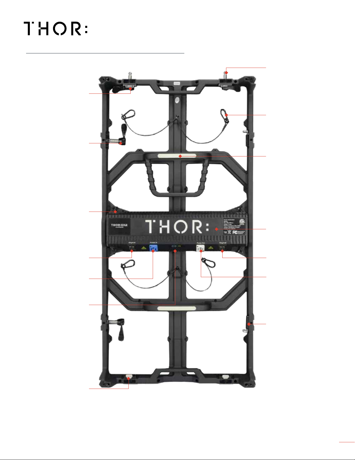
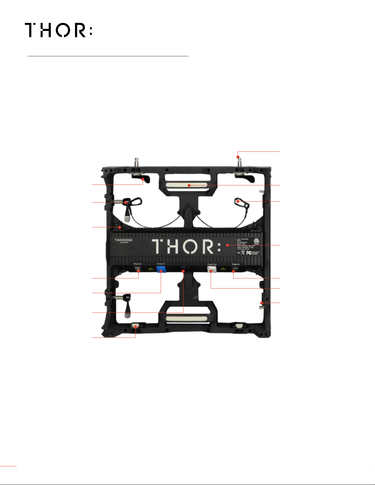
LED Module SMD 2020 gold wire SMD 2020 gold wire SMD 2020 gold wire
Driving IC Module MBI IC Drivers with S-PWM MBI IC Drivers with S-PWM MBI IC Drivers with S-PWM
Serviceability Front / Rear Front / Rear Front / Rear
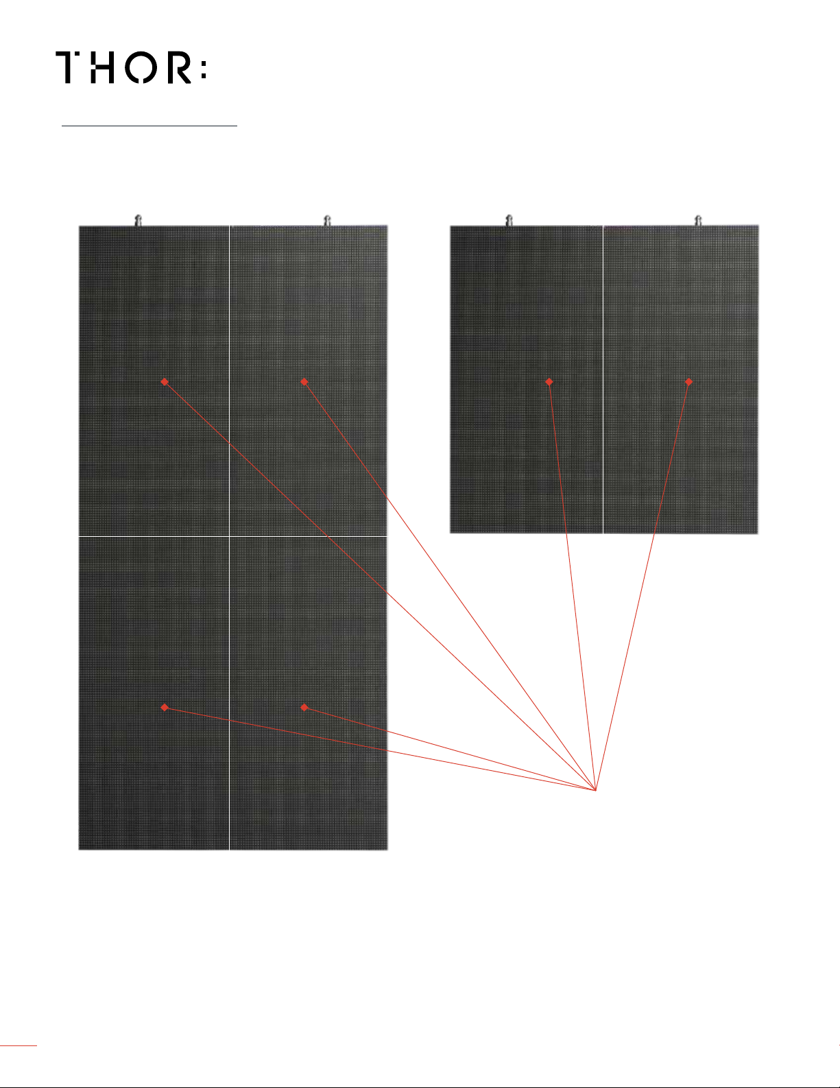
Panel Dimensions
500mm x1000mm 500 x 1000 x 88mm
(19.7” x 39.37” x 3.5")
500 x 1000 x 88mm
(19.7” x 39.37” x 3.5")
500 x 1000 x 88mm
(19.7” x 39.37” x 3.5")
500mm x 500mm 500 x 500 x 88mm
(19.7” x 19.7” x 3.5")
500 x 500 x 88mm
(19.7” x 19.7” x 3.5")
500 x 500 x 88mm
(19.7” x 19.7” x 3.5")
Hardware Options Fly & Ground Stack Fly & Ground Stack Fly & Ground Stack
Processor Platform/Receiving Card Brompton Brompton R2 Brompton R2 N/A
NovaStar NovaStar A8s NovaStar A8s NovaStar A5s Plus
Driving Method 1/14 scan 1/12 scan 1/16 scan
Gray Scale 16 bit 14 bit 14 bit
Refresh Rate 3,840+ Hz 3,840+ Hz 3,840+ Hz
Brightness Control Brompton 1250 steps 1250 steps N/A
NovaStar 256 steps 256 steps 256 steps
Pixel Conguration 500mm x1000mm 168 x 336 (w x h) 56,448 144 x 288 (w x h) 41,472 128 x 256 (w x h) 32,768
500mm x 500mm 168 x 168 (w x h) 28,224 144 x 144 (w x h) 20,736 128 x 128 (w x h) 16,384
Module Conguration 500mm x1000mm 2 x 2 2 x 2 2 x 2
500mm x 500mm 1 x 2 1 x 2 1 x 2
Chassis - Straight Standard Standard Standard
Chassis - Curving Option* +/- 0°, 2.5°, 5°, 7.5°, 10° +/- 0°, 2.5°, 5°, 7.5°, 10° +/- 0°, 2.5°, 5°, 7.5°, 10°
Operating Temperature -30° to 50° C -30° to 50° C -30° to 50° C
Operating Humidity 10% to 90% 10% to 90% 10% to 90%
Power Input 120/240 Volt at 50/60 Hz 120/240 Volt at 50/60 Hz 120/240 Volt at 50/60 Hz
Power Consumption 500mm x1000mm 300W max. 150W avg. 300W max. 100W avg. 300W max. 100W avg.
500mm x 500mm 200W max. 100W avg. 200W max. 75W avg. 200W max. 75W avg.
BTU/hr 500mm x1000mm 1024 max. 500 avg. 1024 max. 342 avg. 1024 max. 342 avg.
500mm x 500mm 683 max. 300 avg. 683 max. 256 avg. 683 max. 256 avg.
Electrical Circuits 120V/20A
(Recommended)
500mm x1000mm 10 panels 10 panels 10 panels
500mm x 500mm 18 panels 18 panels 18 panels
Flown Maximum Rigging Height 14M (46’) 14M (46’) 14M (46’)
Ground Stacked Maximum Height 6M (20’) 6M (20’) 6M (20’)
Chassis Material Die Cast Aluminum Die Cast Aluminum Die Cast Aluminum
Weight 500mm x1000mm 14.5 kg (32 lbs) 14.5 kg (32 lbs) 14.5 kg (32 lbs)
500mm x 500mm 10.5 kg (24 lbs) 10.5 kg (24 lbs) 10.5 kg (24 lbs)
IP Rating IP31 IP31 IP31
Certications FCC, ETL, EMC FCC, ETL, EMC FCC, ETL, EMC
Life Span 100,000+ Hours 100,000+ Hours 100,000+ Hours
Limited Warranty 2 years 2 years 2 years
SPECIFICATIONS
*Special Order Only

www.THORav.us | sales@thorav.us | (763) 999-4253
™ & ® 2018 THOR AV. © 2022 THOR AV.
8
LED MODULES
500mm X 500mm500mm X 1000mm
FRONT VIEW

www.THORav.us | sales@thorav.us | (763) 999-4253
™ & ® 2018 THOR AV. © 2022 THOR AV. 9
RATCHETING LOCKS
DATA IN DATA OUT
POWERCON IN POWERCON OUT
POWER & TEST
PATTERN BUTTON
POWER SUPPLY
THUMB SCREWS
GUIDE PINS
GUIDE PIN
LOCK RECEIVERS
STRAIGHT LOCK
RECEIVERS
LED MODULE SAFETY
CARABINER & CABLE
CHASSIS HANDLE/STEP
REMOVABLE
PDB
LATCH LOCKS
REAR VIEW 500mm X 1000mm

www.THORav.us | sales@thorav.us | (763) 999-4253
™ & ® 2018 THOR AV. © 2022 THOR AV.
10
RATCHETING LOCKS
LATCH LOCKS
DATA IN DATA OUT
POWERCON IN
POWERCON OUT
POWER & TEST
PATTERN BUTTON
POWER SUPPLY
THUMB SCREWS
GUIDE PINS
GUIDE PIN
LOCK RECEIVERS
STRAIGHT LOCK
RECEIVERS
LED MODULE SAFETY
CARABINER & CABLE
CHASSIS HANDLE/STEP
REMOVABLE
PDB
REAR VIEW 500mm X 500mm

www.THORav.us | sales@thorav.us | (763) 999-4253
™ & ® 2018 THOR AV. © 2022 THOR AV. 11
1000mm x 170mm x 100mm
39
33
//
88
” x 6
1111
//
1616
” x 3
1515
//
1616
”
8.89 kg / 19.6 lbs
Flybar/Ground Stack Bar 1M
230mm x 120mm x 64mm
9” x 4 ¾” x 2 ½”
.72 kg / 1.6 lbs
Locking Clamp
500mm x 170mm x 100mm
19
1111
//
1616
” x 6
1111
//
1616
” x 3
1515
//
1616
”
4.63 kg / 10.2 lbs
Flybar/Ground Stack Bar .5M
Flown and Ground Stack Install
Ground Stack Install
800mm x 80mm x 120mm
31 ½” x 3
11
//
88
” x 4 ¾”
8.16 kg / 18 lbs
Rear Ground Bar .9M
1000mm 250mm x 50mm
39
33
//
88
”x 9
1313
//
1616
” x 1
1515
//
1616
”
3.76 kg / 8.3 lbs
Square Frame Truss
PARTS

www.THORav.us | sales@thorav.us | (763) 999-4253
™ & ® 2018 THOR AV. © 2022 THOR AV.
12
1000mm x 50mm x 50mm
39
33
//
88
” x 1
1515
//
1616
” x 1
1515
//
1616
”
1.59 kg / 3.5 lbs
Draw Bar 1M
1257mm x 200mm x 102mm
49 ½” x 8” x 4”
2.7 kg / 6 lbs
Adjustable Draw Bar 1M
600mm x 50mm x 50mm
23
55
//
88
” x 1
1515
//
1616
” x 1
1515
//
1616
”
.9 kg / 2 lbs
Draw Bar .6M
Ground Stack Install
PARTS

www.THORav.us | sales@thorav.us | (763) 999-4253
™ & ® 2018 THOR AV. © 2022 THOR AV. 13
DIMENSIONS
19 1111
//
1616
”
500mm 377//
1616
”
88mm
39 33
//
88
”
1000mm
19 1111
//
1616
”
500mm

www.THORav.us | sales@thorav.us | (763) 999-4253
™ & ® 2018 THOR AV. © 2022 THOR AV.
14
MECHANICAL
Structural integrity for all types of LED wall installation applications (Flown and Ground Stack) is required
for each site and veried by a structural engineer.
See Important Safety Considerations on page 16.
STRUCTURAL
ELECTRICAL
Ground Stack LED walls require ballasting a percentage of the total weight. Ballast the LED wall by
distributing evenly on the Rear Ground Bars.
Ballast Weight Calculator
Wall Height, 1-3 meters — 50% of wall weight
Wall Height, 4 meters — 75% of wall weight
Wall Height, 5 meters — 100% of wall weight
Wall Height, 6 meters — 100%* of wall weight
If a wall weighs 3,300lbs., then the total ballasting weight is 1650lbs. If there are 12 Rear Ground Bars for
this LED wall, 137.5lbs. is needed for each Rear Ground Bar.
*At 6 meters we recommend adding another row of Rear Ground Bar and another set of Rear Ground
Truss.
Verify the mounting structure load capacity (truss, purlins, schedule 80 pipe, unistrut, etc). Determine
adequate amount of pick points for stabilizing LED wall.
BALLASTING
RIGGING
EDGE Panels require 110-240 VAC, 50-60 Hz and should be 16A or less. Proper grounding is required.
POWER

www.THORav.us | sales@thorav.us | (763) 999-4253
™ & ® 2018 THOR AV. © 2022 THOR AV. 15
VIDEO SYSTEM
THOR LED Panels are available with Brompton and NovaStar processing. Contact THOR for specics.
Pixel capacity per port may vary based on LED wall mapping conguration and pixel pitch.
PROCESSING
LED PANELS PER PROCESSOR PORT
EDGE 2.9 EDGE 3.4 EDGE 3.9
60Hz 120Hz 180Hz 240Hz 60Hz 120Hz 180Hz 240Hz 60Hz 120Hz 180Hz 240Hz
8 bit
Panel Qty 9 4 3 2 12 6 4 3 16 8 5 4
10 bit
Panel Qty 7 3 2 1 10 5 3 2 12 6 4 3
12 bit
Panel Qty 6321 8422 10532
EDGE 3.4 EDGE 3.4 EDGE 3.9
60Hz 120Hz 180Hz 240Hz 60Hz 120Hz 180Hz 240Hz 60Hz 120Hz 180Hz 240Hz
8 bit
Panel Qty 18 9 6 4 25 12 8 6 32 16 10 8
10 bit
Panel Qty 14 7 4 3 20 10 6 5 25 12 8 6
12 bit
Panel Qty 12 6 4 3 16 8 5 4 21 10 7 5
EDGE LED Panel
500mm x 500mm
EDGE LED Panel
500mm x 1000mm

www.THORav.us | sales@thorav.us | (763) 999-4253
™ & ® 2018 THOR AV. © 2022 THOR AV.
16
THOR AV products must be used in accordance with local, state, federal and industry regulations. In
addition to this, THOR AV is not responsible for any rigging, attachments and accessories provided by
third party manufacturers.
INTENDED USE
The EDGE series LED panels are for indoor applications only. Installations require professionally trained
personnel.
Do not use this product near water or damp environments. Do not expose the unit to direct sun light or
heating units as the internal components’ temperature may rise and shorten the life of the components.
Provide for proper airow around product. Do not install near products that produce high levels of heat.
INSPECT PRODUCT
Inspect all products and perform safety related checks before deployment. Heed all warnings and
precautions in this manual and notices marked on the product.
Protect the power cord from being walked on or pinched particularly at plugs, convenience receptacles,
and the point where they connect to the product. Do not use the unit if the electrical power cord is frayed
or broken.
INSTALLATION GUIDELINES
The responsibility to evaluate the reliability of any rigging or mounting method for their application is
solely the user’s responsibility. Rigging is to be carried out by experienced professionals. Abide by the
Working Load Limit (WLL) of third party equipment for suspension points, chain hoists and additional
rigging hardware.
Verify structural integrity meets engineering requirements for ying, ground stacking and wall mounting
applications. Utilize safety measures at all times, including safety slings and cables.
IMPORTANT SAFETY CONSIDERATIONS

Loosely secure Flybars together with Flybar Bracket.
Insert Latch Guide Pins into receiving holes on Flybar and adjacent panels. Align panels and lock into position by twisting the Latch Guide Pin. Do not over
tighten. Continue until rst row is complete. Tighten Flybar Brackets (gure 1). For additional rows, align panels and lock into position.
1
3
Secure and level Flybars to weight bearing structure using Clamps or Eyebolts.
LEVEL
2
www.THORav.us | sales@thorav.us | (763) 999-4253
™ & ® 2018 THOR AV. © 2022 THOR AV. 17
FLOWN APPLICATION

Push latch lever, on Flybar or panel, to lock or release Latch Guide Pins. New Latch lever may need to be pushed in and out a few times for Latch Guide Pins
to properly secure into place.
Verify LED panels are aligned before tightening into place.
4
5
6
4
FLOWN APPLICATION
www.THORav.us | sales@thorav.us | (763) 999-4253
™ & ® 2018 THOR AV. © 2022 THOR AV.
18

www.THORav.us | sales@thorav.us | (763) 999-4253
™ & ® 2018 THOR AV. © 2022 THOR AV. 19
Align Ground/Flybar onto Rear Ground Bar.
Insert and twist Ground/Flybar Spring Bolt into Rear Ground Bar. Tighten
when positioned accordingly.
Attach Ground/Flybar to adjacent Ground/Flybar by loosely securing bracket to adjacent Ground/Flybar using a 6mm hex until rst row panels are in place.
Tighten or loosen as needed. Do not over tighten.
Level Ground/Flybars using Rear Ground Bar Feet either by hand or using
inset hex. Level feet to eliminate seams in the LED wall as more panels are
added.
LEVEL
1
4
2
3
GROUND STACKED LED WALL

www.THORav.us | sales@thorav.us | (763) 999-4253
™ & ® 2018 THOR AV. © 2022 THOR AV.
20
GROUND STACKED LED WALL
Insert Latch Guide Pins into receiving holes on panel.
Place other panels next to each other and insert Latch Guide Pins into
receiving holes on panel and twist to lock into place. Check that face (LED
Modules) of panels are ush with each other before tightening into place.
Insert Latch Guide Pins into adjacent panel. Aligning panels, lock into position by twisting the Latch Guide Pin. Do not over tighten. Continue steps 7-8 until
rst row is complete. Adjust Rear Ground Bar Feet as more weight is added to each row. For additional rows, align panels into position. To remove seams,
loosen Latch Locks and adjust feet and tighten Latch Locks again. Finally, tighten Flybar Brackets (gure 1).
The receiving hole on panel, locks the Ground/Flybar Guide Pins into
position. Push to lock or release.
5
8
67
Table of contents
Other THOR Lighting Equipment manuals
Popular Lighting Equipment manuals by other brands

American DJ
American DJ LED Pixel Tube 360 Information sheet

Westgate
Westgate LSWX-5-30W-K-PC Series Installation instructions manual

Anslut
Anslut 422-322 installation instructions

Finelite
Finelite HP-4 Recessed Mounting and Feed Guide

Velleman
Velleman HQ Power VDLLBPS6 user manual

Vision X
Vision X ADV Adventure Series Installation instructions & user manual