THOR RIDGE User manual

RIDGE
User Guide
Document reference: RIDGE User Guide 22v8
Distribution date: August 15, 2022
© 2018 THOR AV. All rights reserved.
No part of this publication may be reproduced or
transmitted in any form or by any means without the
express written consent of the publisher.

www.THORav.us | sales@thorav.us | (763) 999-4253
™ & ® 2018 THOR AV. © 2022 THOR AV.
ii
TO REDUCE THE RISK OF ELECTRIC SHOCK, DO NOT REMOVE COVER. NO USER SERVICEABLE PARTS
INSIDE.
The lightning ash with arrowhead symbol, within an equilateral triangle, is intended to alert
the user to the presence of un-insulated and/or potentially dangerous voltage within the
products enclosure that may be of sufcient magnitude to constitute a risk of electric shock to
persons.
The exclamation point within an equilateral triangle is intended to alert the user to the
presence of important operating and maintenance (servicing) instructions in the literature
accompanying the appliance.
IMPORTANT SAFETY INSTRUCTIONS
1. Intended use for the RIDGE series is for indoor applications.
2. Inspect all products and perform safety related checks before deployment.
3. Read and understand this entire manual.
4. Keep this manual available for reference.
5. Heed all warnings and precautions in this manual and notices marked on the product.
6. Do not use this product near water or damp environments.
7. Do not block any ventilation openings. Install in accordance with the manufacturer’s instructions.
8. Provide for proper airow around product. Do not install near products that produce high levels
of heat. Do not expose the unit to direct sun light or heating units as the internal components’
temperature may rise and shorten the life of the components.
9. Do not defeat the safety purpose of the polarized or grounding-type plug. A polarized plug has two
blades with one wider than the other. A grounding type plug has two blades and a third grounding
prong.
10. Protect the power cord from being walked on or pinched particularly at plugs, convenience
receptacles, and the point where they connect to the product. Do not use the unit if the electrical
power cord is frayed or broken.
11. THOR AV products must be used in accordance with local, state, federal and industry regulations.
The responsibility to evaluate the reliability of any rigging or mounting method for their application
is solely the user’s responsibility. Rigging is to be carried out by experienced professionals.
12. Abide by the Working Load Limit (WLL) of third party equipment for suspension points, chain hoists
and additional rigging hardware.
13. Verify structural integrity meets engineering requirements for ying, ground stacking and wall
mounting applications.
14. THOR AV is not responsible for any rigging, attachments and accessories provided by third party
manufacturers.
15. Utilize safety measures at all times, including safety slings and cables.
16. Unplug this product during lightning storms or when unused for long periods of time.
17. Refer all servicing to qualied service personnel. There are no user serviceable components inside
the product.
18. The product shall not be exposed to moisture. Do not touch the unit with wet hands. Do not handle
the unit or power cord when your hands are wet or damp.
19. The product should be connected to a power supply only of the type described in the operating
instructions or as marked on the product.
CARE
• From time to time you should wipe off the front and side panels and the cabinet with a dry soft
cloth. Do not use rough material, thinners, alcohol or other chemical solvents or cloths since this may
damage the nish or remove the panel lettering.
• The manufacturer cannot be held responsible for damages caused to persons, personal possessions,
or data due to an improper or missing ground connection.
RIDGE LED PANEL INSTRUCTIONS

www.THORav.us | sales@thorav.us | (763) 999-4253
™ & ® 2018 THOR AV. © 2022 THOR AV. iii
All THOR AV LED products are warranted to the original purchaser to be free of defects in materials and
workmanship for a period of two years from date of purchase. During this period, THOR AV will, at its
discretion, repair the defective unit or replace it with a new or rebuilt one.
The warranty does NOT cover:
• Damages caused by abuse, accident, improper use, improper handling, improper operation,
improper installation/disassembly of the display or any other customer misconduct.
• Damages due to installation of any unauthorized hardware, accessories, consumable parts or
components.
• Defects, malfunctions or damages caused during transportation.
• Units on which the product serial number has been removed or altered.
• Units that have been serviced by unauthorized personnel.
All implied warranties, including warranties on merchantability and tness, are limited in time to the length
of this warranty. Some states do not allow time limitations on implied warranties, so this limitation may not
apply to you. THOR AV’s liability is limited to the repair or replacement of its product. THOR AV shall in no
way be held liable for incidental or consequential damages resulting from the use of their product or its
software, including, without limitation, damages from loss of business prots, business interruption, loss
of business information or other pecuniary loss. Some states do not allow the exclusion or limitation of
incidental or consequential damages, so the above limitation or exclusion may not apply to you.
REPAIR POLICY
Please contact support@thorav.us to obtain an RMA number prior to returning your product to THOR AV.
Do not return the product to the place of purchase. Write the RMA number on the outside of the shipping
carton. Any product sent to us without a valid RMA number will be refused.
Shipping Address:
THOR AV
Attn: RMA Number
8821 Zealand Ave. N, Ste. B
Brooklyn Park, MN 55445 USA
Include the following with the product: a brief description of the problem, your name, return shipping
address, phone number and the RMA number. Do not include any accessories. THOR AV is not
responsible for any damage to or loss of the product during transit. We recommend that customers obtain
a receipt and tracking number for all packages shipped to us. Turnaround time on repairs is generally ten
business days. If you live outside of the United States, please contact your local distributor for warranty
service.
WARRANTY SERVICE
You will be responsible for shipping charges to THOR AV and the product will be returned by THOR AV.
We reserve the right to inspect any product that may be the subject of any warranty claim before repair is
carried out. To qualify for warranty service, documentation showing the date of purchase may be required.
Final determination of warranty coverage lies solely with THOR AV.
NON-WARRANTY SERVICE
If it is determined that the product does not meet the terms of our warranty, you will be billed for labor,
materials, return shipping and insurance. There is a $100 USD minimum charge for materials and labor.
Appropriate shipping charges will be applied. We require payment in advance of repair by credit card;
we accept Visa and Master Card. In the event the charges are over the minimum charge, THOR AV will
contact you and inform you of the cost of the repair before any work is completed.
THOR LIMITED WARRANTY

www.THORav.us | sales@thorav.us | (763) 999-4253
™ & ® 2018 THOR AV. © 2022 THOR AV.
iv
TABLE OF CONTENTS
SAFETY INSTRUCTIONS
RIDGE LED PANEL INSTRUCTIONS II
WARRANTY
THOR LIMITED WARRANTY III
OVERVIEW
RIDGE LED PANEL 1
SPECIFICATIONS 2
ANATOMY 3
Front View 3
Rear View 4
Power Data Box 5
Parts 6
Dimensions 8
INSTALLATION REQUIREMENTS
MECHANICAL 9
ELECTRICAL 9
VIDEO SYSTEM 9
INSTALL APPLICATION
IMPORTANT SAFETY CONSIDERATIONS 10
FLOWN LED WALL 11
Using Flybar 11
Using Ground/Flybar 13
GROUND STACKED LED WALL 14
WALL MOUNTED LED WALL 19
CONNECTION GUIDE
POWER CONNECTION 23
DATA CONNECTION 24
PROCESSORS
BROMPTON TECHNOLOGY 25
NOVASTAR 25


www.THORav.us | sales@thorav.us | (763) 999-4253
™ & ® 2018 THOR AV. © 2022 THOR AV. 1
RIDGE LED wall panels offers outstanding
performance with exible install options. RIDGE
can be installed in ground stack, own, or wall
mounted congurations. This LED panel series is
ideal for House of Worship, Fixed Installations,
Virtual Production, and Signage.
• 1.8mm, 2.5mm, and 3.7mm pixel pitches
• Brompton and NovaStar processing options
• Easy servicing from front or back
• Best-in-class on-camera performance
• Easily visible in all levels of ambient light
• Ideal for churches, stages, corporate board
rooms and lobbies, and VR/XR studio
production.
INDOOR LED WALL PANEL
RIDGE LED PANEL

www.THORav.us | sales@thorav.us | (763) 999-4253
™ & ® 2018 THOR AV. © 2022 THOR AV.
LISTED
E498026
2
1.8 Brompton 2.5 Brompton
2.5i NovaStar
3.7 Brompton
3.7i NovaStar
Pixel Pitch 1.8mm 2.5mm 3.7mm
Calibrated Brightness 1175 nits 1200 nits 1250 nits
Viewing Angle 140° x 140° 140° x 140° 140° x 140°
Closest Viewer 7 FT / 2.1M 10 FT / 3M 18 FT / 5M
LED Module SMD 1010 gold wire SMD 2121 gold wire SMD 2121 gold wire
Driving IC Module MBI IC Drivers with S-PWM MBI IC Drivers with S-PWM MBI IC Drivers with S-PWM
Serviceability Front / Rear Front / Rear Front / Rear
Panel Dimensions 600 x 337.5 x 58mm
(23.62” x 13.29” x 2.29”)
600 x 337.5 x 58mm
(23.62” x 13.29” x 2.29”)
600 x 337.5 x 58mm
(23.62” x 13.29” x 2.29”)
Hardware Options Fly, Ground Stack, & Wall Mount Fly, Ground Stack, & Wall Mount Fly, Ground Stack, & Wall Mount
Processor Platform/Receiving
Card*
Brompton Brompton R2 Brompton R2 Brompton R2
NovaStar N/A NovaStar A5s Series NovaStar A5s Series
Driving Method 1/15 scan 1/15 scan 1/15 scan
Gray Scale 16 bit 16 bit 16 bit
Refresh Rate 3,840+ Hz 3,840+ Hz 3,840+ Hz
Brightness Control
Brompton 1175 steps 1200 steps 1250 steps
NovaStar N/A 256 steps 256 steps
Pixel Conguration 320 x 180 (w x h) 57,600 240 x 135 (w x h) 32,400 160 x 90 (w x h) 14,400
Module Conguration 2 x 1 2 x 1 2 x 1
Chassis - Straight Standard Standard Standard
Operating Temperature -30° to 50° C -30° to 50° C -30° to 50° C
Operating Humidity Up to 90% Up to 90% Up to 90%
Power Input 120/240 Volt at 50/60 Hz 120/240 Volt at 50/60 Hz 120/240 Volt at 50/60 Hz
Power Consumption 150W max. 50W avg. 120W max. 40W avg. 120W max. 40W avg.
BTU/hr 437 max. 137 avg. 437 max. 137 avg. 437 max. 137 avg.
Electrical Circuits 120V/20A 24 panels 24 panels 24 panels
Flown Maximum Rigging
Height 8M (26.25’) 8M (26.25’) 8M (26.25’)
Ground Stacked Maximum
Height 5M (16.4’) 5M (16.4’) 5M (16.4’)
Chassis Material Die Cast Aluminum Die Cast Aluminum Die Cast Aluminum
Weight 8.5 kg (18.6 lbs) 8.5 kg (18.6 lbs) 8.5 kg (18.6 lbs)
IP Rating IP31 IP31 IP31
Certications FCC, ETL, EMC, UL FCC, ETL, EMC, UL FCC, ETL, EMC, UL
Life Span 100,000+ Hours 100,000+ Hours 100,000+ Hours
Limited Warranty 2 years 2 years 2 years
SPECIFICATIONS

www.THORav.us | sales@thorav.us | (763) 999-4253
™ & ® 2018 THOR AV. © 2022 THOR AV. 3
LED MODULES
MODULE GUIDE POSTS
MODULES
CONNECTOR
MODULES
HANDLE
FRONT VIEW
www.THORav.us | sales@thorav.us | (763) 999-4253
™ & ® 2018 THOR AV. © 2022 THOR AV.
4
LATCH LOCKS
LOCKING CLAMP
SOCKET
WALL MOUNT
SCREW HOLE
GUIDE PIN LATCH
LED MODULE
SAFETY SCREWS
CHASSIS HANDLE
REMOVABLE
POWER & DATA BOX
REAR VIEW

www.THORav.us | sales@thorav.us | (763) 999-4253
™ & ® 2018 THOR AV. © 2022 THOR AV. 5
DATA IN/OUT DATA IN/OUT
PowerCON IN PowerCON OUT
POWER & TEST
PATTERN BUTTON
POWER SUPPLY
THUMB SCREWS
POWER DATA BOX
www.THORav.us | sales@thorav.us | (763) 999-4253
™ & ® 2018 THOR AV. © 2022 THOR AV.
6
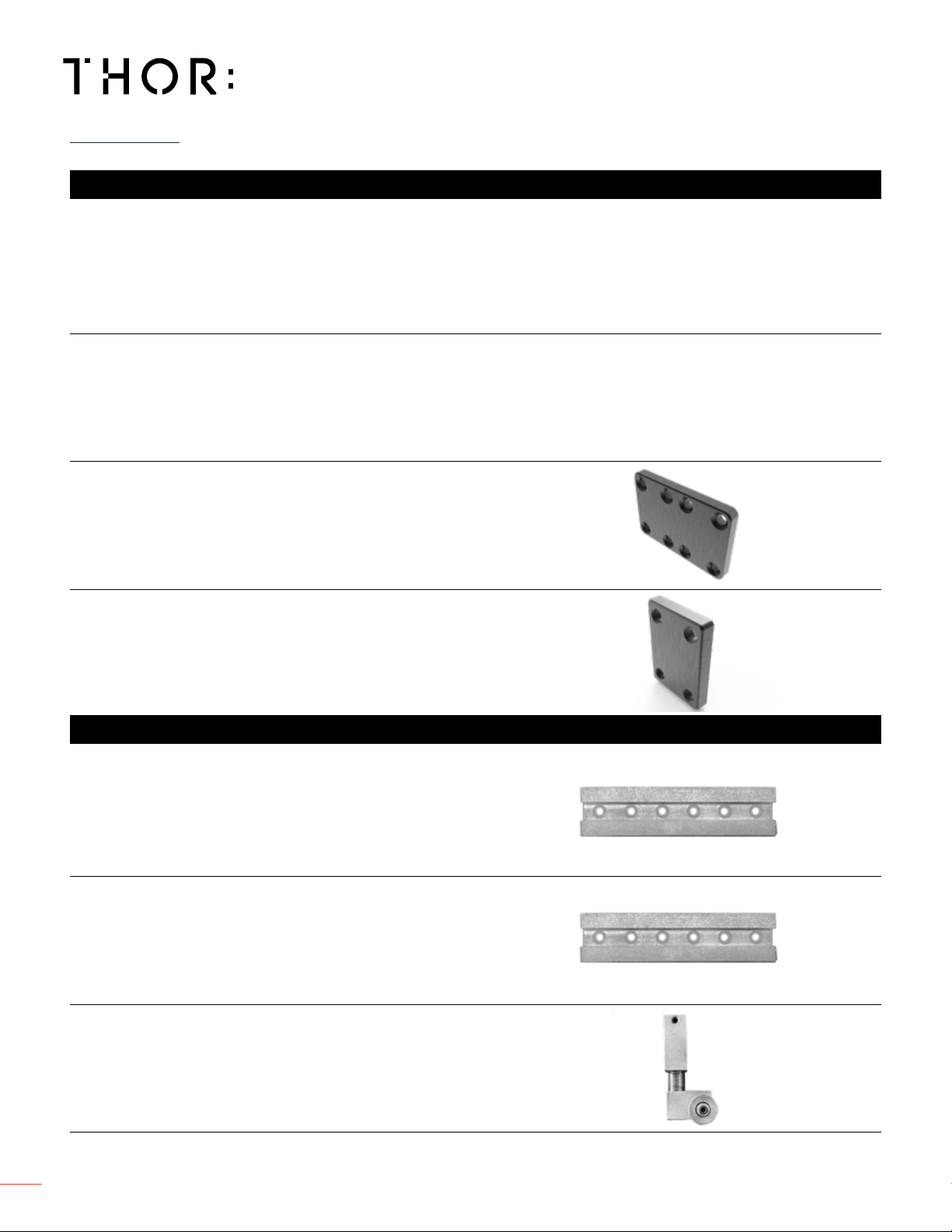
600mm x 66.67mm x 4.69mm
23 ⅝” x 2 ⅝” x 4
1111
//
1616
”
4.5 kg / 9.92 lbs
1200mm x 66.67mm x 119mm
47 ¼” x 2 ⅝” x 4
1111
//
1616
”
8.5 kg / 18.74 lbs
98mm x 75mm x 10mm
3 ⅞” x 2
1515
//
1616
” x .39”
.18 kg / .34 lbs
75mm x 48mm x 10mm
2
1515
//
1616
” x 1 ⅞” x ⅜”
.09 kg / .12 lbs
1800mm x 38.1mm x 25.4mm
70 ⅞” x 1 ½” x 1”
2.45 kg / 5.4 lbs
2400mm x 38.1mm x 25.4mm
94 ½” x 1 ½” x 1”
1.8 kg / 4 lbs
114.3mm x 63.5mm x 38.1mm
4 ½” x 2 ½” x 1 ½”
.36 kg / .8 lbs
Flybar 600mm
Wall Mount 1800mm Track
Flybar 1200mm
Wall Mount 2400mm Track
Flybar Bracket
Wall XYZ Mount
Flybar Endcap
Flown Install
Wall Mount Install
PARTS

www.THORav.us | sales@thorav.us | (763) 999-4253
™ & ® 2018 THOR AV. © 2022 THOR AV. 7
600mm x 80mm x100mm
23 ⅝” x 3 ⅛” x 3
1515
//
1616
”
4.63 kg / 10.1 lbs
1200mm x 80mm x 100mm
47 ¼” x 3 ⅛” x 3
1515
//
1616
”
9.53 kg / 21 lbs
850mm x 160mm x 105mm
33
77
//
1616
” x 6
55
//
1616
” x 4 ⅛”
3.76 kg / 8.3 lbs
675mm 240mm x 50mm
26
99
//
1616
”x 9
77
//
1616
” x 1
1515
//
1616
”
2.5 kg / 5.5 lbs
1010mm x 240mm x 50mm
39 ¾” x 9
77
//
1616
” x 1
1515
//
1616
”
3.18 kg / 7 lbs
240mm x 105mm x 116mm
9
77
//
1616
” x 4 ⅛” x 4
99
//
1616
”
.64 kg / 1.4 lbs
1200mm x 50mm x 30mm
47 ¼” x 1
1515
//
1616
” x 1
33
//
1616
”
1.81 kg / 4 lbs
Ground/Flybar 600mm
Ground/Flybar 1200mm
Ladder Truss 1010mm
Locking Clamp
Rear Drawbar 1200mm
Ground Stack Install
Rear Ground Truss 850mm
Ladder Truss 765mm
Ground and Flown Install
Ground and Flown Install
PARTS
www.THORav.us | sales@thorav.us | (763) 999-4253
™ & ® 2018 THOR AV. © 2022 THOR AV.
8
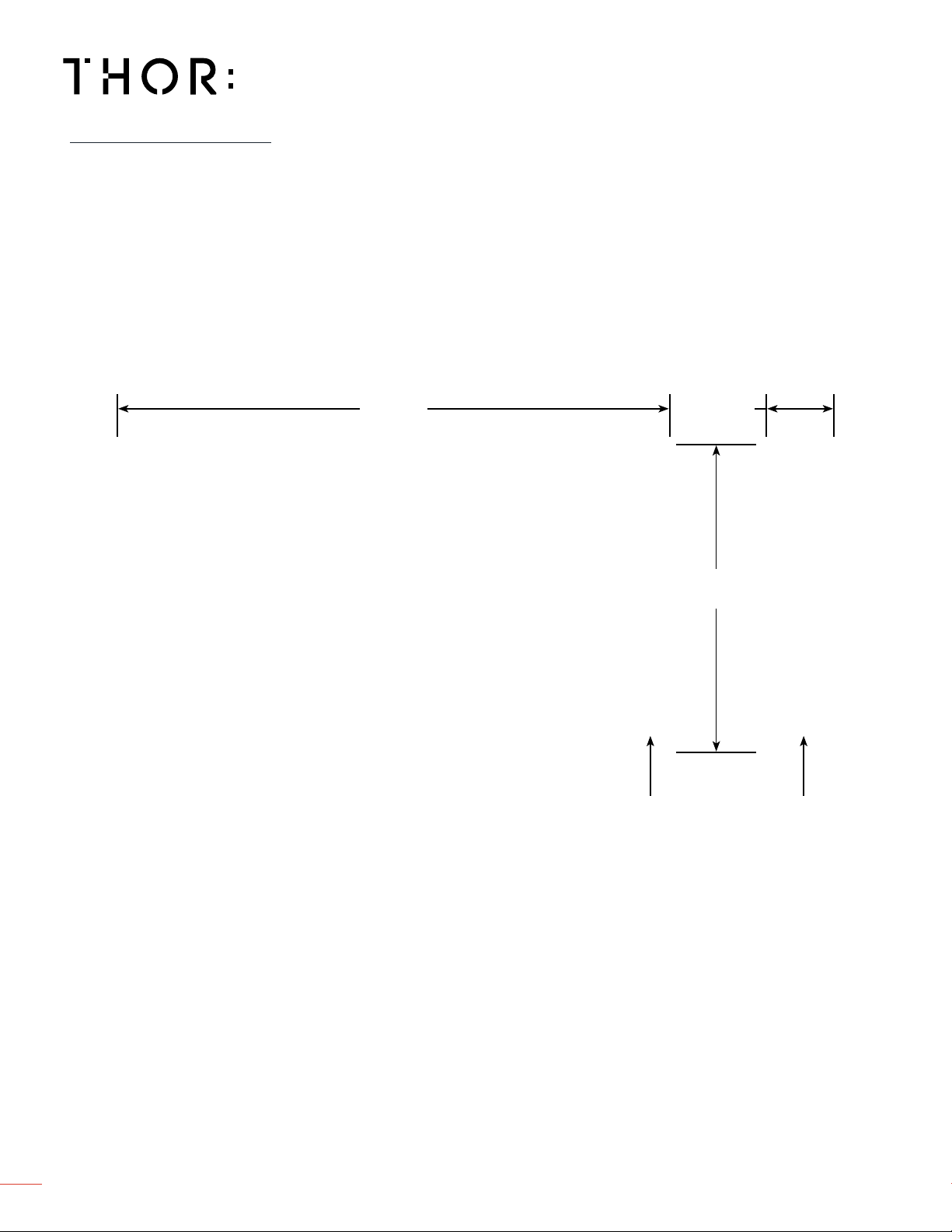
DIMENSIONS
23 ⅝”
600mm
255
//
1616
”
58mm
13 55
//
1616
”
337.5mm
M5 M3
www.THORav.us | sales@thorav.us | (763) 999-4253
™ & ® 2018 THOR AV. © 2022 THOR AV. 9
MECHANICAL
VIDEO SYSTEM
THOR LED Panels are available with Brompton and NovaStar processing. Contact THOR for specics.
Pixel capacity per port may vary based on LED wall mapping conguration and pixel pitch.
PROCESSING
LED PANELS PER PROCESSOR PORT
RIDGE 1.8 RIDGE 2.5 RIDGE 3.7
60Hz 120Hz 180Hz 240Hz 60Hz 120Hz 180Hz 240Hz 60Hz 120Hz 180Hz 240Hz
8 bit
Panel Qty 9 4 3 2 16 8 5 4 36 18 12 9
10 bit
Panel Qty 7 3 2 1 12 6 4 3 29 14 9 7
12 bit
Panel Qty 6 3 2 1 10 5 3 2 24 12 8 6
Structural integrity for all types of LED wall installation applications (Flown and Ground Stack) is required
for each site and veried by a structural engineer.
See Important Safety Considerations on page 10.
STRUCTURAL
ELECTRICAL
Ground Stack LED walls require ballasting a percentage of the total weight. Ballast the LED wall by
distributing evenly on the Rear Ground Bars.
Ballast Weight Calculator
Wall Height, 1-3 meters — 50% of wall weight
Wall Height, 4 meters — 75% of wall weight
Wall Height, 5 meters — 100% of wall weight
Wall Height, 6 meters — 100%* of wall weight
If a wall weighs 3,300lbs., then the total ballasting weight is 1650lbs. If there are 12 Rear Ground Bars for
this LED wall, 137.5lbs. is needed for each Rear Ground Bar.
*At 6 meters we recommend adding another row of Rear Ground Bar and another set of Rear Ground
Truss.
Verify the mounting structure load capacity (truss, purlins, schedule 80 pipe, unistrut, etc). Determine
adequate amount of pick points for stabilizing LED wall.
BALLASTING
RIGGING
EDGE Panels require 110-240 VAC, 50-60 Hz and should be 16A or less. Proper grounding is required.
POWER

www.THORav.us | sales@thorav.us | (763) 999-4253
™ & ® 2018 THOR AV. © 2022 THOR AV.
10
THOR AV products must be used in accordance with local, state, federal and industry regulations. In
addition to this, THOR AV is not responsible for any rigging, attachments and accessories provided by
third party manufacturers.
INTENDED USE
The RIDGE series LED panels are for indoor applications only. Installations require professionally trained
personnel.
Do not use this product near water or damp environments. Do not expose the unit to direct sun light or
heating units as the internal components’ temperature may rise and shorten the life of the components.
Provide for proper airow around product. Do not install near products that produce high levels of heat.
INSPECT PRODUCT
Inspect all products and perform safety related checks before deployment. Heed all warnings and
precautions in this manual and notices marked on the product.
Protect the power cord from being walked on or pinched particularly at plugs, convenience receptacles,
and the point where they connect to the product. Do not use the unit if the electrical power cord is frayed
or broken.
INSTALLATION GUIDELINES
The responsibility to evaluate the reliability of any rigging or mounting method for their application is
solely the user’s responsibility. Rigging is to be carried out by experienced professionals. Abide by the
Working Load Limit (WLL) of third party equipment for suspension points, chain hoists and additional
rigging hardware.
Verify structural integrity meets engineering requirements for ying, ground stacking and wall mounting
applications. Utilize safety measures at all times, including safety slings and cables.
IMPORTANT SAFETY CONSIDERATIONS
www.THORav.us | sales@thorav.us | (763) 999-4253
™ & ® 2018 THOR AV. © 2022 THOR AV. 11
1
3
2
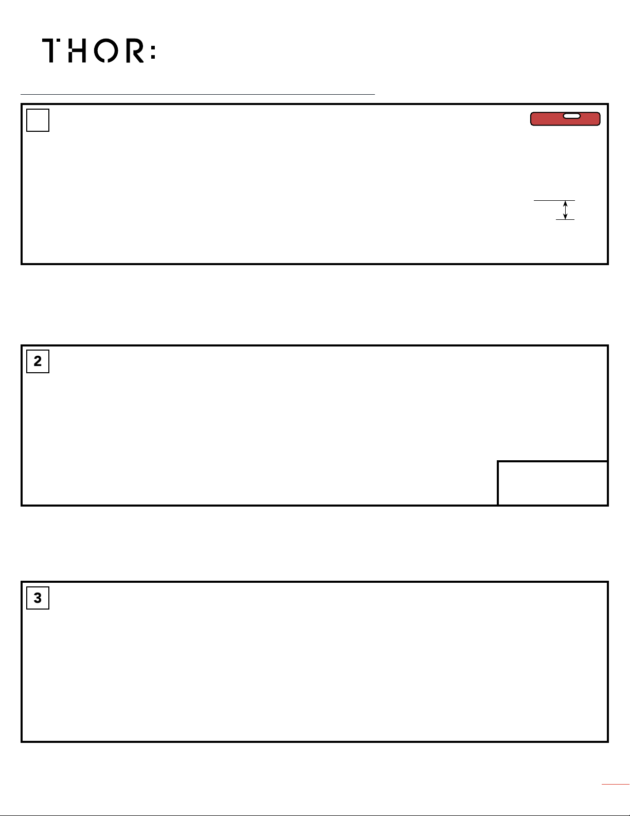
Secure and level Flybars to weight bearing structure using Eyebolt. Eyebolts are removable. Use a thin wall 1-5
/
32” socket on under side of Flybar.
LEVEL
1 ¾ in
(4.5 cm)
Loosely secure Flybars together with Flybar Bracket. Use large Phillips screwdriver and spare screws on Flybar.
Attach aesthetic End Cap to either end of Flybar assembly.
FLOWN APPLICATION - USING FLYBAR
www.THORav.us | sales@thorav.us | (763) 999-4253
™ & ® 2018 THOR AV. © 2022 THOR AV.
12
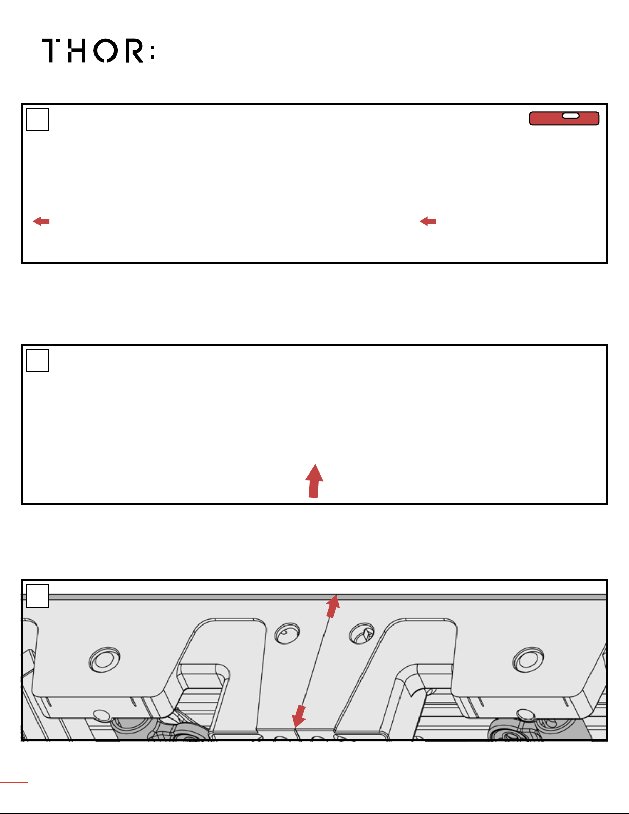
Insert Latch Guide Pins into receiving holes on Flybar and adjacent panels. Align panels and lock into position by twisting the Latch Guide Pin. Do not over
tighten. Continue until rst row is complete. For additional rows, align panels and lock into position.
Push latch lever, on Flybar or panel, to lock or release Latch Guide Pins. New Latch lever may need to be pushed in and out a few times for Latch Guide Pins
to properly secure into place.
Verify LED panels are aligned before tightening into place.
LEVEL
4
6
5
FLOWN APPLICATION - USING FLYBAR
www.THORav.us | sales@thorav.us | (763) 999-4253
™ & ® 2018 THOR AV. © 2022 THOR AV. 13
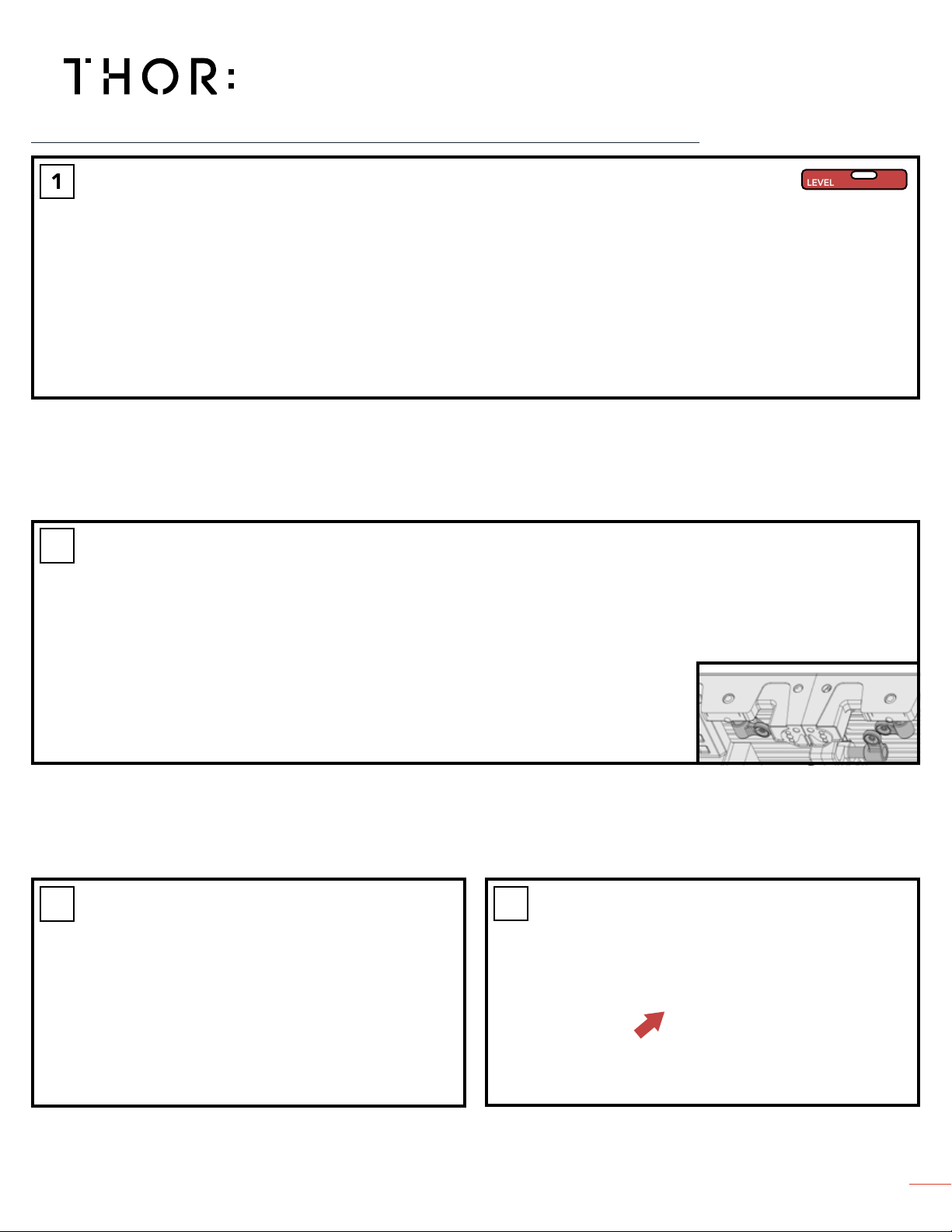
1
2
LEVEL
Secure and level Ground/Flybars to weight bearing structure using Eyebolt.
Insert Latch Guide Pins into receiving holes on Ground/Flybar and adjacent panels. Align panels and lock into position by twisting the Latch Guide Pin. Do not
over tighten. Continue until rst row is complete. For additional rows, align panels and lock into position.
Attach Ground/Flybar Locking Triangle Eyebolt to adjacent Ground/Flybar
and tighten or loosen as needed. Do not over tighten.
The receiving hole for the Latch Guide Pin locks panels into position. Push to
lock or release.
4
3
FLOWN APPLICATION - USING GROUND/FLYBAR

www.THORav.us | sales@thorav.us | (763) 999-4253
™ & ® 2018 THOR AV. © 2022 THOR AV.
14
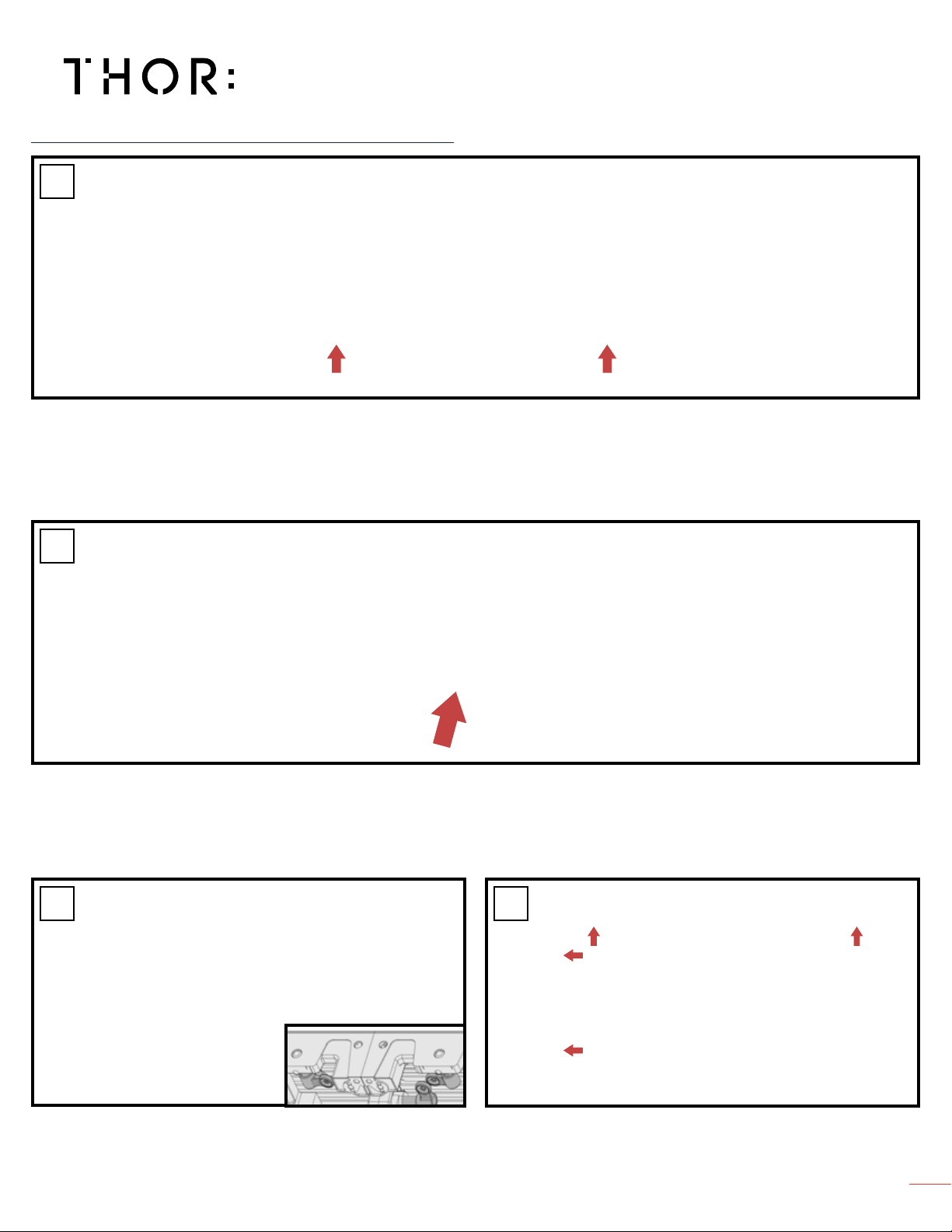
Connect Rear Ground Truss to Ground/Flybar using truss bolt and cotter pin. Truss Bolt can only be inserted one direction. Use rubber mallet to insert truss
bolt completely before inserting Cotter Pin.
To eliminate seams in the LED wall, level Ground Stack hardware. Adjust
using 8mm hex key.
Attach Ground/Flybar Locking Triangle Eyebolt to adjacent Ground/Flybar and tighten or loosen as needed. Do not over tighten.
Level Ground/Flybars by adjusting attached feet with 8mm hex key. Extends
from 0-1 inch.
LEVEL LEVEL
1
4
3
2
36 ¾ in
(933 mm)
4 ¾ in
(120 mm)
33
1515
//
3232
in
(850 mm)
≤ 1 in (26 mm) ≤ 1 ¼ in (32 mm)
GROUND STACKED LED WALL
www.THORav.us | sales@thorav.us | (763) 999-4253
™ & ® 2018 THOR AV. © 2022 THOR AV. 15
GROUND STACKED LED WALL
Insert Latch Guide Pins into receiving holes on panel and twist to lock into place.
Place other panels next to each other and insert Latch Guide Pins into
receiving holes on panel and twist to lock into place. Verify LED panels are
aligned before tightening into place.
Insert Latch Guide Pins into adjacent panel and secure. Do not over
tighten. Continue steps 7-8 until rst row is complete. Adjust leveling feet
if necessary as more weight is added to each row. For additional rows, align
panels and lock into position.
The receiving hole on panel, locks the Ground/Flybar Guide Pins into position. Push to lock or release.
5
8
6
7
Table of contents
Other THOR Lighting Equipment manuals


 85-05481 user manual")


