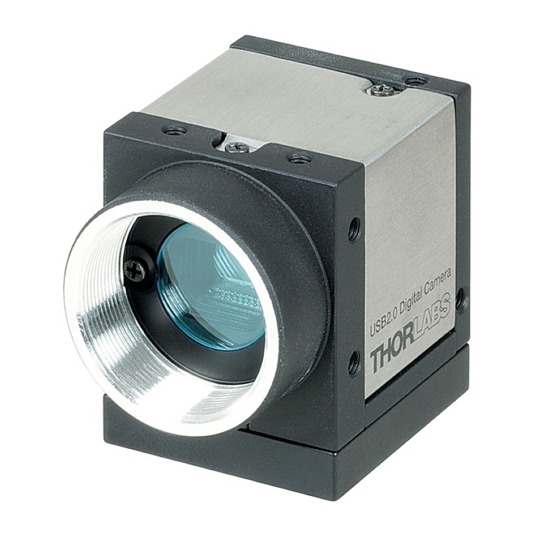
THORLABS 1500M Series User manual

1500M-Series
Scientific Grade Digital
Camera
User Guide

Table of Contents
Chapter 1 Warning Symbol Definitions.............................................................................................. 4
Chapter 2 Safety .................................................................................................................................... 5
2.1. Precautions......................................................................................................................5
2.2. Product Care....................................................................................................................6
2.2.1. Service .................................................................................................................................. 6
2.2.2. Accessories and Customization ............................................................................................ 6
Chapter 3 Description........................................................................................................................... 7
3.1. Introduction .....................................................................................................................7
3.2. Receiving and Unpacking...............................................................................................7
3.2.1. Important Information Regarding the Power Supply ............................................................. 7
3.3. Supplied Equipment........................................................................................................8
3.3.1. Optional Items ....................................................................................................................... 8
Chapter 4 Setup & Installation............................................................................................................. 9
4.1. Pre-Installation ................................................................................................................9
4.1.1. Gigabit Ethernet (GigE) System ............................................................................................ 9
4.1.2. Camera Link System ............................................................................................................. 9
4.2. Installing the Software..................................................................................................10
4.2.1. Getting Started .................................................................................................................... 10
4.2.2. Typical Installation ............................................................................................................... 10
4.2.3. Driver Installation ................................................................................................................ 12
4.2.4. Custom Setup (may be required for special circumstances) .............................................. 13
4.2.5. Custom Driver Installation (Expert Mode) ........................................................................... 14
4.2.6. Installing 3rd Party Software Applications ............................................................................ 15
4.3. Connecting the Camera................................................................................................18
4.3.1. Multiple Camera Operation ................................................................................................. 19
4.4. Optical and Mechanical Mounting Considerations....................................................20
4.4.1. Using a C-Mount Lens ........................................................................................................ 20
4.4.2. Mounting the Camera .......................................................................................................... 20
4.4.3. Using the Camera with a Cage System .............................................................................. 21
4.4.4. Compatible Adapters for the Camera ................................................................................. 21
4.5. Optical Front End..........................................................................................................21
4.5.1. Description of Components ................................................................................................. 23
4.6. Optical Front End Procedures .....................................................................................24
4.6.1. Removing the C-mount Lock Ring Assembly ..................................................................... 24
4.6.2. Filter Removal and Replacement Procedure ...................................................................... 25
4.6.3. Re-assembly of the C-mount Lock Ring and Back-Focus Adjustment ............................... 26
4.7. Auxiliary Connector......................................................................................................27
4.7.1. Pin Descriptions .................................................................................................................. 27
4.7.2. Signal Descriptions ............................................................................................................. 27
4.7.3. Auxiliary I/O Cable Requirements ....................................................................................... 28
Chapter 5 Operation.............................................................................................................................29
5.1. Starting the Camera......................................................................................................29
5.2. Camera Timing Diagrams.............................................................................................29

Scientific Grade Digital Video Camera Chapter 1: Warning Symbol Definitions
ITN000089-D02, Rev HPage 3
Chapter 6 Specifications .....................................................................................................................31
6.1. CCD Specifications.......................................................................................................31
6.2. Quantum Efficiency.......................................................................................................31
6.3. IR Blocking Filter...........................................................................................................32
6.4. Imaging Specifications.................................................................................................33
6.4.1. Example Frame Rates ........................................................................................................ 33
Chapter 7 Mechanical Drawings.........................................................................................................34
7.1. 1500M-GE-TE.................................................................................................................34
7.2. 1500M-GE.......................................................................................................................34
7.3. 1500M-CL-TE..................................................................................................................35
7.4. 1500M-CL .......................................................................................................................35
7.5. Switching Power Supply...............................................................................................36
Chapter 8 Troubleshooting.................................................................................................................37
8.1. Interface .........................................................................................................................37
8.3. Optical............................................................................................................................38
8.4. Operational ....................................................................................................................38
8.5. Software.........................................................................................................................39
Chapter 9 Maintenance........................................................................................................................40
9.1. Cleaning Guidelines......................................................................................................40
9.1.1. Cleaning the Lens of Optical Assembly .............................................................................. 40
9.1.2. Standard (Non-Cooled) Camera Precautions ..................................................................... 40
9.1.3. TE-Cooled Camera Precautions ......................................................................................... 40
9.1.4. Cleaning the Infrared Filter (Standard and TE-Cooled Cameras) ...................................... 41
Chapter 10 Regulatory...........................................................................................................................42
10.1. Waste Treatment is Your Own Responsibility............................................................42
10.2. Ecological Background ................................................................................................42
10.3. Certifications and Compliance – CE Declaration of Conformity ..............................43
10.4. FCC Statement...............................................................................................................44
10.5. Auxiliary I/O Cable Requirements................................................................................44
Chapter 11 Warranty ..............................................................................................................................45
11.1. General Product Warranty............................................................................................45
11.2. Specific Warranties.......................................................................................................45
11.2.1.Optomechanics ................................................................................................................... 45
11.2.2.Optical Tables and Breadboards ........................................................................................ 45
11.2.3.Lasers and Imaging Systems .............................................................................................. 45
11.2.4.Opto-Electronics, Control Electronics, Optics, and Nano-Positioning Product Lines ......... 45
11.2.5.Non-Warranty Repairs ........................................................................................................ 45
11.2.6.Warranty Exclusions ........................................................................................................... 45
Chapter 12 Thorlabs Worldwide Contacts..........................................................................................46

Scientific Grade Digital Video Camera Chapter 1: Warning Symbol Definitions
ITN000089-D02, Rev HPage 4
Chapter 1 Warning Symbol Definitions
Below is a list of warning symbols you may encounter in this manual or on your device.
Symbol Description
Direct Current
Alternating Current
Both Direct and Alternating Current
Earth Ground Terminal
Protective Conductor Terminal
Frame or Chassis Terminal
Equipotentiality
On (Supply)
Off (Supply)
In Position of a Bi-Stable Push Control
Out Position of a Bi-Stable Push Control
Caution: Risk of Electric Shock
Caution: Hot Surface
Caution: Risk of Danger
Warning: Laser Radiation
Caution: Spinning Blades May Cause Harm

Scientific Grade Digital Video Camera Chapter 2: Safety
ITN000089-D02, Rev HPage 5
Chapter 2 Safety
2.1. Precautions
Please read the instruction manual carefully before operating your Digital Video Camera. All statements regarding
safety and technical specifications will only apply when the unit is operated correctly.
Refer to this User’s Guide whenever the following symbols are encountered on the Digital Video Camera and
Power Supply.
ATTENTION
This symbol indicates that additional information is available in this user guide.
This equipment is intended for laboratory use only and is not certified for medical applications,
including but not limited to, life support situations.
Transportation and delivery may cause the Digital Video Camera to be warm or cool upon
receipt. Please wait for the device to reach room temperature before attempting to operate.
Mobile telephones, cellular phones, or other radio transmitters are not to be used within the
range of three meters of this unit since the electromagnetic field intensity may exceed the maximum
allowed disturbance values according to EN50082-1.
CAUTION
Check the supply voltage of the system BEFORE plugging in the power supply. Make sure the
included power cord is the correct type for the service you are connecting to AND connected to a
properly grounded power outlet (100 – 240 VAC; 50 – 60 Hz).
There are NO user accessible fuses in this Digital Video Camera or the included External
Power Supply.
Do not open the Digital Video Camera or the External Power Supply. Doing so is dangerous
and could result in damage to the unit or death to the user.
WARRANTY WARNING
Do not open the Digital Video Camera or the external power supply. There are no user serviceable
parts in this product. Opening the device will void your warranty. Any modification or servicing of
this system by unqualified personnel renders Thorlabs free of any liability. This device can only be
returned when packed into the complete original packaging, including all foam packing inserts. If
necessary, ask for replacement packaging. Please contact Thorlabs’ Technical Support at

Scientific Grade Digital Video Camera Chapter 2: Safety
ITN000089-D02, Rev HPage 6
2.2. Product Care
Handle the system with care during transportation and unpacking. Banging or dropping the system can damage
the unit or lower system performance. If the system is mishandled during shipment, the optical components may
become misaligned, which could lead to a decrease in the image quality. If this happens, the system will need to
be realigned by qualified personnel. To ensure proper care and operation of your Digital Video Camera, please
follow the handling instructions below.
• Do not store or operate in a damp, closed environment.
• Do not use solvents on or near the equipment.
• Keep away from dust, dirt, and air-borne pollutants (including cigarette smoke). The system is not
designed for outdoor use. Protect the equipment from rain, snow, and humidity.
• Do not expose to mechanical or thermal extremes. Protect the equipment from rapid variation in
temperature.
• Handle all connectors with care. Do not use unnecessary force as this may damage the connectors.
• Clean using a soft, lint free cloth. Use of isopropyl alcohol is permitted, however do not immerse in any
liquid or solvent.
• Clean any accessible optical surfaces with an appropriate optics grade tissue or cloth.
2.2.1. Service
Only trained and approved Thorlabs’ personnel should service the system. Please contact Thorlabs’ Technical
Support at techsupport@thorlabs.com and a member of our team will be happy to assist you.
2.2.2. Accessories and Customization
Although the system is easily adapted for custom interfaces, to achieve the listed specifications, this system
should only be used with accessories provided by Thorlabs. Any modification or servicing by unqualified
personnel renders the warranty null and void, leaving Thorlabs free of liability. Please contact Thorlabs for
questions on customization.

Scientific Grade Digital Video Camera Chapter 3: Description
ITN000089-D02, Rev HPage 7
Chapter 3 Description
3.1. Introduction
Our 1500M series of cameras consists of four models: the 1500M-GE, 1500M-GE-TE, 1500M-CL, and 1500M-
CL-TE. The models are distinguished by their interface method (GigE vs. Camera Link) and whether they are TE-
cooled or not. The 1500M is based on the Sony ICX285 interline CCD, which provides 1392x1020 pixel resolution
and 6.45 µm square pixels with high quantum efficiency and low noise. The 1500M is offered in both standard and
cooled configurations, with a choice of Gigabit Ethernet or Camera Link interface. Additionally, the 1500M is
bundled with the full complement of Thorlabs Scientific Imaging (TSI) software.
For end-users, the ThorCam software application provides full control of the camera through an intuitive user
interface, and it allows the user to acquire, pan, zoom, analyze, and save images and metadata.
For developers, TSI also offers a software developer’s kit, which includes a comprehensive API to streamline the
integration of any TSI camera into your system. After software installation, the SDK can be found in the \Program
Files\Thorlabs Imaging\documentation folder. This is the same for 32 and 64 bit distributions.
This manual is a functional overview of the camera, and it is meant to be a companion to the ThorCam User
Manual and the SDK.
3.2. Receiving and Unpacking
Your 1500M camera was thoroughly tested and carefully packed at the factory. Once the camera shipment is
accepted for delivery, the carrier assumes full responsibility for its safe arrival. Should you receive your shipment
with any damage—concealed or apparent—please contact the carrier at once. The carrier will instruct you on how
to initiate a damage claim. If a visual inspection reveals damage upon receipt, it must be noted on the freight bill
or express receipt and the notation signed by the carrier’s agent. Failure to do so can result in the carrier refusing
to honor the claim.
To return your camera to TSI for service, you must first contact your local Thorlabs office or distributor and
request a Return Material Authorization (RMA). Returns will not be accepted without an RMA. See Chapter 11,
titled “Warranty Information” for details.
3.2.1. Important Information Regarding the Power Supply
CAUTION
The switching power supply that is provided by TSI for use with this camera operates automatically
over the following range of voltages (100 – 240 VAC; 50 – 60 Hz). Make sure the included power cord
is the correct type for the service you are connecting to AND connected to a properly grounded
power outlet.
Dangerous voltage exists within the power supply. Do not tamper with or open the supply under any
circumstances. Doing so may expose lethal voltage to personnel and will void the warranty.

Scientific Grade Digital Video Camera Chapter 3: Description
ITN000089-D02, Rev HPage 8
3.3. Supplied Equipment
The following is a list of equipment that may be supplied with your 1500M camera, depending on your order
configuration. Figure 1 below shows the different available configurations.
Supplied Equipment
Camera Type
1500M Non-Cooled
1500M Cooled
Available Interface Options
GigE
Includes Intel® Gigabit CT PCI Express Desktop Adapter
and 14' CAT 5e Cable
Camera Link Interface
Includes VisionLink F4 Camera Link Board
and 5 m Camera Link Cable
Accessories
• Regulated switch-mode Power Supply with 72”
cord (Supplied line cord appropriate for user’s
country or region)
• Spanner Wrench
• Lens cap (and IR filter removal tool)
Included Software
Thorlabs Camera Software and SDK
(Available for download from www.thorlabs.com)
Figure 1 Available Camera Configurations
3.3.1. Optional Items
• Auxiliary I/O Patch cable – The auxiliary connector on the camera allows the user to access optional
camera control and internal status signals (see Chapter 4).
Order Thorlabs 1500-CAB1 and TSI-IOBOB.
1500M Cooled
or Non-Cooled Camera
GigE Interface Configuration
CameraLink Interface Configuration

Scientific Grade Digital Video Camera Chapter 4: Setup & Installation
ITN000089-D02, Rev HPage 9
Chapter 4 Setup & Installation
4.1. Pre-Installation
Before proceeding with installation of hardware or software, please identify whether your camera interface is
Camera Link or Gigabit Ethernet (GigE).
4.1.1. Gigabit Ethernet (GigE) System
If you purchased a Gigabit Ethernet camera, an Intel PCIe adapter card is provided for use on desktop computer
systems. Although the system will work with other adapters (including laptop GigE adapters), it is recommended
that this card be used for optimal performance on all desktop installations.
Recommended Installation Sequence
1. Power down the computer.
2. Taking necessary precautions, install the Intel PCIe GigE adapter.
3. Turn on the computer and accept Windows driver recommendations for the newly installed hardware.
4. Run the software installer – follow the steps outlined in the next section, including driver installation.
5. Connect then power on camera and run ThorCam application software.
4.1.2. Camera Link System
If you purchased a Camera Link camera, an EDT PCIe VisionLink F4 interface card is provided. Other Camera
Link interface cards are not supported.
Recommended Installation Sequence
1. Run the software installer, follow the steps outlined in the next section.
2. Power down the computer.
3. Taking necessary precautions, install the EDT PCIe Camera Link interface card.
4. Turn on the computer.
5. Accept the driver installation recommendations for the newly installed hardware.
6. Connect then power on camera and run ThorCam application software.

Scientific Grade Digital Video Camera Chapter 4: Setup & Installation
ITN000089-D02, Rev HPage 10
4.2. Installing the Software
Although similar, the installation sequence for the GigE and Camera Link systems vary. Please see the steps
below to install your system properly.
4.2.1. Getting Started
If installing the software from a downloaded copy from our website please go to section 4.2.2, otherwise insert the
CD-ROM included with your camera accessories into a suitable CD-ROM drive on your computer. The disk will
automatically start and the installation process will begin with the following screens:
Select the “Run Install_Thorlabs_Camera_Software.hta” option, then press the “Install Software” button.
Note: Once the “Install Software” button is pressed, it may take a few minutes for the installer to
determine your computer’s configuration. We thank you for your patience.
4.2.2. Typical Installation
The information provided in this section is meant to describe the steps required for a typical system, involving a
single camera (either Gigabit Ethernet or Camera Link), in which the user picks certain options. Some steps that
typically require an affirmative response are not detailed, for the sake of clarity. Multiple camera systems and
other “advanced” options are described in the following chapter. The InstallShield Wizard will guide you through
the program setup process and driver installation as shown on the following pages.

Scientific Grade Digital Video Camera Chapter 4: Setup & Installation
ITN000089-D02, Rev HPage 11
Proceed to Driver Installation (Next Page)

Scientific Grade Digital Video Camera Chapter 4: Setup & Installation
ITN000089-D02, Rev HPage 12
4.2.3. Driver Installation

Scientific Grade Digital Video Camera Chapter 4: Setup & Installation
ITN000089-D02, Rev HPage 13
4.2.4. Custom Setup (may be required for special circumstances)
See below for a depiction of the custom setup process.
Typical Setup is complete, you may
now proceed to Section 4.3 that will
describe how to connect and power on
your camera.
Once the camera is connected and
powered up, follow the steps below from
your Start Menu:
“Start”“Thorlabs”
“Scientific Imaging”“ThorCam”

Scientific Grade Digital Video Camera Chapter 4: Setup & Installation
ITN000089-D02, Rev HPage 14
4.2.5. Custom Driver Installation (Expert Mode)
See below for the custom driver installation process.

Scientific Grade Digital Video Camera Chapter 4: Setup & Installation
ITN000089-D02, Rev HPage 15
4.2.6. Installing 3rd Party Software Applications
After installation of Thorlabs components is complete, you have the option to install plug-ins for select 3rd party
image analysis packages you may already have installed on your computer, such as Matlab™. (Note: Thorlabs
only provides ImageJ with this installation – and only if you have run a “custom” or “complete” installation.)
Note: These plug-ins are only required if you wish to control the camera directly from within the 3rd party software.
It is not necessary to install the plug-ins if your preferred mode of operation is, for example, to use ThorCam or
Micro-manager for acquisition and then analyze saved images via ImageJ.
To install a plug-in, please follow the steps shown below, and run the Setup utilities related to the 3rd party
applications that you wish to use.
Select the 3rd party software of choice and run the
Setup.exe application to install the plug-in.
Follow the steps until Setup exits.
Then run the 3rd party application of choice, following the
necessary steps to choose the installed plug-in.
After the MatLab IMAQ driver is
installed, you may control the
camera directly from MatLab.
To begin, run MatLab and click
on the “Apps” tab. Select
“Image Acquisition” and then
click on the selected camera in
the Hardware Browser window.
To control the camera, click on
“Device Properties”. Set the
desired camera parameters, and
then Start Preview.

Scientific Grade Digital Video Camera Chapter 4: Setup & Installation
ITN000089-D02, Rev HPage 16
To begin, run ImageJ and select “TSICamera” from the list of available Plugins
Special note for users of Micro-manager software: support for Thorlabs scientific cameras is included
when you run versions 1.4.14 and later. If you wish to download or update your Micro-Manager software,
please visit: http://valelab.ucsf.edu/~MM/MMwiki/index.php/Micro-Manager.
Note: The Micro-manager installer creates a copy of ImageJ on your desktop. Therefore, if you wish to use Micro-
manager, a “Typical” installation of ThorCam will suffice, and it is not necessary to install ImageJ using a
“Custom” or “Complete” installation option.
Before using your camera within Micro-manager, first make sure that your camera is properly installed and
powered-ON. You may run a session of ThorCam to confirm that the camera, software and drivers are properly
installed. Then, shut down your ThorCam session and start a Micro-manager session.
The following steps launch the Hardware Configuration Wizard within Micro-manager, to create (or modify) a
configuration that includes a TSI camera.
ImageJ is installed as part of the “Custom” or
“Complete” installation options and includes the
necessary plug-ins for operating a TSI Camera
directly from ImageJ. To run this plug-in use
the version of ImageJ located through the
Windows Start Menu:
“Start”“Thorlabs”
“Scientific Imaging”“ImageJ”

Scientific Grade Digital Video Camera Chapter 4: Setup & Installation
ITN000089-D02, Rev HPage 17

Scientific Grade Digital Video Camera Chapter 4: Setup & Installation
ITN000089-D02, Rev HPage 18
4.3. Connecting the Camera
To connect the camera, follow the steps and refer to the diagram below.
1. With the power supply turned off, connect the DE-9 from the power supply to the DE-9 on the back of the
camera. The connector on the camera is labeled “POWER”.
2. Connect the auxiliary cable (optional, ordered separately) into the port on the camera labeled as “AUX”.
3. Connect the interface cable, either a Gigabit Ethernet (GigE) or a Camera Link, based on your camera
model.
- If you are utilizing a Cat5e Gigabit Ethernet (GigE) Cable: Connect the Ethernet cable to the port
on the camera labeled “GigE”. Connect the other end into the port of the Intel® Gigabit CT PCI
Express desktop adapter, installed in the computer.
-If you are utilizing a Camera Link Cable: Connect the camera link cable into the port labeled
“CAMERA LINK”. Connect the other end into the port of the EDT VisionLink F4 camera link card,
installed in the computer. Always connect to the port closest to the mother-board of the
computer. In Figure 2 below, this would be the left most connector labeled “0” – your computer
orientation may vary.
Figure 2 Diagram of Connectors on Camera (Left shows GigE configuration, Right shows Camera
Link configuration)
DB-9 Power Connector
Auxillary Cable Port
Ethernet
Cable Connection
Camera Link
Cable Connection

Scientific Grade Digital Video Camera Chapter 4: Setup & Installation
ITN000089-D02, Rev HPage 19
4.3.1. Multiple Camera Operation
If multiple camera operation is required, it is recommended that a Gigabit Ethernet switch topology be setup, as
shown below. When multiple cameras are connected and powered on, they will be visible in the Image Detector
dropdown of Hardware Setup panel. Both control and display revert to the camera that is selected from the
dropdown menu.
Figure 3 Gigabit Ethernet Switch Topology Setup

Scientific Grade Digital Video Camera Chapter 4: Setup & Installation
ITN000089-D02, Rev HPage 20
4.4. Optical and Mechanical Mounting Considerations
4.4.1. Using a C-Mount Lens
For the best results, the use of a C-Mount lens that matches the optical format of the 2/3” imaging area is
recommended. For more information on Thorlabs C-Mount lenses, please visit www.thorlabs.com
C-mount lenses are specified with a flange focal distance of 17.5 mm. However, there can be considerable
variation in the flange focal distance among commercially available lenses.
To accommodate the variation in commercially available lenses, the camera has an adjustable flange focal range
of ± 1.5 mm. A procedure to set the flange focal distance is described in the next section.
Figure 4 Camera Shown with C-Mount Lens (not supplied) Using the C-Mount Adapter
4.4.2. Mounting the Camera
On most commercial microscopes, the use of a 0.63x adapter is recommended in order to match the optical
format of the 2/3” imaging area.
The adjustable flange focus may also be used to parfocalize a microscope, as described in the next section.
Figure 5 Camera Shown on Microscope Using C-Mount Adapter
Four 1/4”-20 tapped holes are provided, one on each side of the housing. These may be used with tripods, or
other optical mounting
This manual suits for next models
4
Table of contents
Other THORLABS Digital Camera manuals

THORLABS
THORLABS DCC3260M User manual

THORLABS
THORLABS LabView DCU2 Series Owner's manual

THORLABS
THORLABS DCU22 Series User manual

THORLABS
THORLABS CC505MU User manual

THORLABS
THORLABS S805 User manual

THORLABS
THORLABS 8051 User manual

THORLABS
THORLABS LP126MU User manual

THORLABS
THORLABS CC215MU User manual

THORLABS
THORLABS DCC Series User manual

THORLABS
THORLABS CS165 Series User manual