1
0546
Contents
Introduction .............................................................................................................................. ii
Abbreviations used in this Manual ...................................................................................... ii
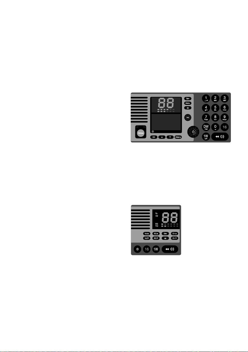
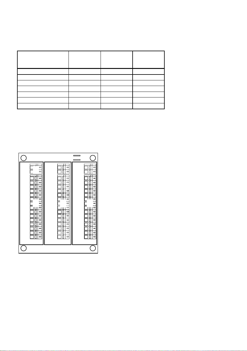
1 The Devices that are Subject to Configuration and Maintenance with the SB5006
Service Tool ........................................................................................................................ 3
2 Physical Connection ......................................................................................................... 4
5
2.1 Physical Connection for CU5000 Software upload.................................................... 5
2.2 Alternative Connection ............................................................................................... 6
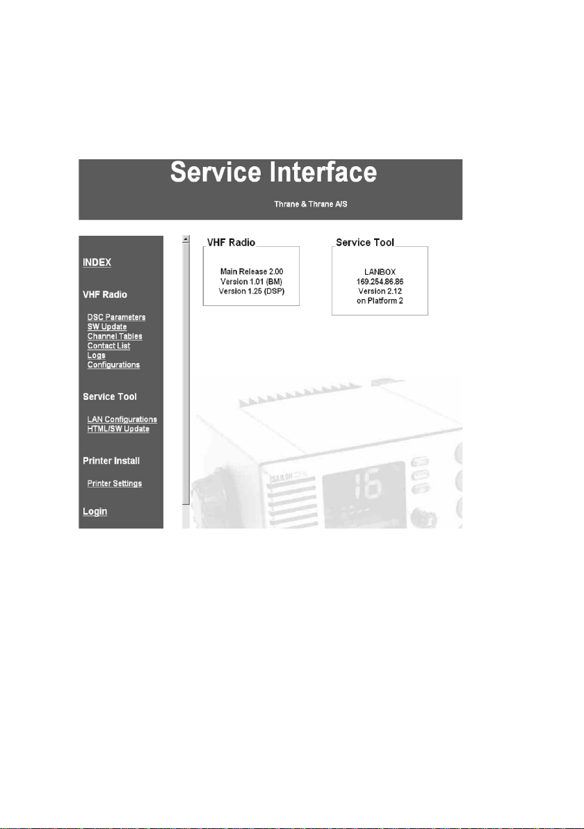
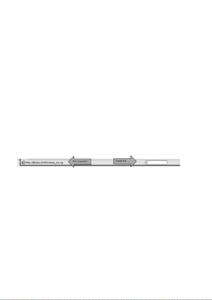
3 Using the Service Interface .............................................................................................. 7
4 Use Scenarios .................................................................................................................... 9
4.1 Configuration Level ..................................................................................................... 9
4.2 Service Level ............................................................................................................ 19
4.3 Printer Configuration on an LB5007 LAN Box ......................................................... 21
5 Appendix – Troubleshooting .......................................................................................... 23
5.1 Preparing the Service PC ......................................................................................... 23
5.2 Connecting the PC.................................................................................................... 23
5.3 Logical Connection ................................................................................................... 23
5.4 Service Tool Software update .................................................................................. 29
6 Known Bugs and Limitations in the Service Tool ....................................................... 31
6.1 Physical Connection Issues ..................................................................................... 31
6.2 Logical Connection Problems................................................................................... 32
6.3 Use configuration scenarios ..................................................................................... 33