THRUSH Aar-O-Vent 4 Series Manual

Manual # OMAV2-SUMP1
High Performance
Hydraulic Separator, with
Air and Dirt Separation
Manual # 9636-1500 Rev-A
340West8thStreet
Peru,IN.46970
PH:765‐472‐3351
FX:765‐472‐3968
www.thrushco.com
COPYRIGHTTHRUSHCO.INC.2015
Operation&MaintenanceManual


Table of Contents
THIS DOCUMENT CONTAINS INFORMATION THAT THRUSH CO. DEEMS CONFIDENTIAL AND PROPRIETARY.
THE BASIC THRUSH CO. PRODUCT REVEALED IN THIS DOCUMENT IS PATENTED, AS ARE CERTAIN
PRODUCT COMPONENTS. IN CONSIDERATION FOR THE RECEIPT OF THIS DOCUMENT, RECIPIENT
AGREES NOT TO REPRODUCE, COPY, USE OR TRANSMIT THIS DOCUMENT OR THE INFORMATION
CONTAINED HEREIN, IN WHOLE OR IN PART, OR TO PERMIT OTHERS TO DO SO, FOR ANY PURPOSE
WITHOUT FIRST OBTAINING THE EXPRESS WRITTEN PERMISSION FROM THRUSH CO. RECIPIENT
FURTHER AGREES TO SURRENDER THIS DOCUMENT UPON REQUEST BY THRUSH CO.
COPYRIGHT THRUSH CO. INC. 2015
Section Description _ Page
1 General Product Information 1
2
3
Safety Information/Warnings
Component Identification and Information
3
4-8
4 Installation and Operation 9-16
5 Maintenance Information 17
6 Parts Ordering/Contact Information 18


Thrush Co.
Manual # 9636-1500
1
Section 1
General Product Information
1.1 Overview
The Aar-O-Vent 4X® is another product in the long line of innovations from Thrush
Co.,INC. It has been carefully assembled and factory tested to provide years of trouble-
free service. This manual provides all the necessary information to allow the
installer/operator to install, operate, service and maintain the Aar-O-Vent 4X. See Figure
1-1 for model designation. This is patented technology.
The Thrush Aar-O-Vent 4X® performs three important tasks in a hydronic heating
system:
remove entrained (dissolved air / gases);
remove suspended dirt particles;
balance the pressures between the primary and secondary circuits.
Entrained air is removed via the presence of a coalescing / catalytic surface; in the form
of bundled stainless steel mesh. The surface of the mesh provides the activation energy
to increase the rate at which the dissolved gases will coalesce and “exit solution” (exit
entrainment). The dissolved gases are attracted (have an affinity for) to the surface of
the mesh where the concentration of the gases increases and results in bubble formation
[at the surface]. The bubbles then rise to the top of the equipment and exit via a
specialize Thrush venting valve called an “air eliminator”.
Both temperature and pressure will also affect the amount of dissolved gases the
carrying fluid will hold (typically water). Both cooling the water and decreasing pressure
will also create a driving force whereby that the dissolved gases will coalesce out of
solution into bubbles. This affect at the coalescing / catalytic surface is the fundamental
principle of operation of this equipment.
The stainless steel mesh also acts as a strainer / filter mechanism which brings the dirt
particles out of suspension such that they will gravity fall to the bottom of the equipment
to be periodically removed at servicing intervals.
Higher pressure on either the “primary” or “secondary” circuit side will equalize with the
other and thus divert a small amount of flow to the other at the point of the equipment.

Thrush Co.
Manual # 9636-1500
2
Figure 1-1 Overview
T4 S R-040 -W
Separation Type
Thrush Velocity Head Type Connection Size Options
R=Removable
F=Fixed
S=Standard Velocity
H=High Velocity
example: 025 = 2.5”
or 100 = 10.0”
A=Air Only
D=Dirt Only
B=Both Air and Dirt
4=Hydraulic Separator
W=with options
X=less options*
Model Designation

Thrush Co.
Manual # 9636-1500
3
Section 2
Safety Information/Warnings
2.1 Safety Information and Warnings
Every practical safety feature has been incorporated into the design and manufacture of
the Thrush Co. Aar-O-Vent 4X. If questions are not answered by this manual, or if
specific installation, operation, and/or maintenance procedures are not clearly
understood, contact your local representative before proceeding. Personnel must, at all
times, observe all safety regulations while performing maintenance or repairs.
All installation, operation, and maintenance procedures should be performed by
qualified, experienced and well trained personnel. The potential exists for severe
personal injury if proper procedures are not followed.
Depending on the size of Aar-O-Vent 4X, the bundle can be quite heavy. It is
recommended that supports be used when removing the head and bundle. Once
all bolts have been removed from the head, the head and bundle are free to drop.
Risk of severe personal injury and/or property damage may occur if the bundle
and head are not properly supported.
The Aar-O-Vent 4X is not designed to be used as a make-up water inlet point.
Using any of the connections for make-up water would impede proper operation
and void the warranty.
System water over 100°F can be very hazardous. Keep flow away from the body
when flushing the unit. Failure to do so could result in serious bodily injury or
property damage.

Thrush Co.
Manual # 9636-1500
4
Section 3
Component Identification and Information
3.1 Component Identification
The following paragraphs contain functional descriptions for each of the major
components of a Thrush Co. Aar-O-Vent 4X.
(4) SIGHT GLASS
ASME NAMEPLATE
REMOVABLE HEAD
BLOW DOWN VALVE
(4) GAUGE TAP
SKIM VALVE
AIR ELIMINATOR
COALESCING MEDIUM
(NOT SHOWN)
OPTIONAL EQUIPMENT
*
*
*
*
Figure 3-1 Components

Thrush Co.
Manual # 9636-1500
5
3.1.1 Coalescing Medium
Aar-O-Vent 4X models incorporate an all stainless steel coalescing medium often
referred to as the bundle. This coalescing medium eliminates virtually any dirt particles,
air bubbles, and/or entrained air from the water by means of an air eliminator or blow
down valve. This patented design resists corrosion and can be easily cleaned.
Figure 3-2 Coalescing Medium

Thrush Co.
Manual # 9636-1500
6
3.1.2 Sight Glass (Optional)
One of the optional features offered on 5” and larger Aar-O-Vent 4X is sight glasses.
Sight glasses allow the user to periodically check the coalescing medium for signs of dirt
build-up.
Figure 3-3 Sight Glass

Thrush Co.
Manual # 9636-1500
7
3.1.3 Removable Head Option
The removable head option allows the user to easily remove the bundle for cleaning or
inspection, available in all models.
REMOVABLE HEAD
COALESCING MEDIUM / BUNDLE
REFERENCE SUBMITTAL DATA
FOR DISTANCE REQUIRED
TO REMOVE BUNDLE
Figure 3-4 Removable Head Detail
Depending on the size of Aar-O-Vent 4X, the bundle can be quite heavy. It is
recommended that supports be used when removing the head and bundle. Once
all bolts have been removed from the head, the head and bundle are free to drop.
Risk of severe personal injury and/or property damage may occur if the bundle
and head are not properly supported.
Thrush Co.
Manual # 9636-1500
8
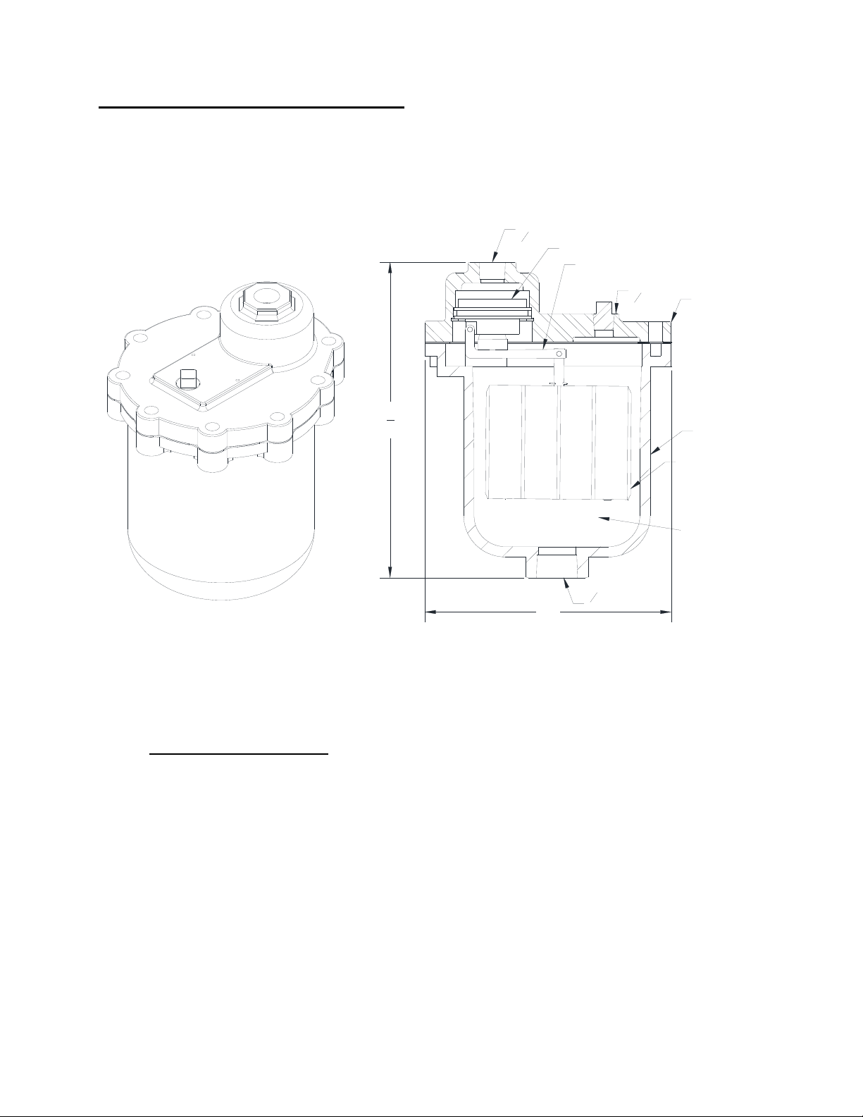
3.1.4 Thrush Model 720 Air Eliminator
The Thrush Model 720 Air Eliminator is a unique high capacity, air elimination device. It
is designed to eliminate air as fast as it can be separated from liquid. The valve will not
open if negative pressure occurs, preventing air from being drawn back into the system.
75
8"
6"
BODY
FLOAT
VALVETAP
14"NPT
34"NPT
DRAINTAP
38"NPT
LEVERASSEMBLY
AIRCOLLECTION
CHAMBER
LID
CONTROLASSEMBLY
Figure 3-5 Air Eliminator
Air Eliminator Operation
The air eliminator is used on the Aar-O-Vent 4X to remove unwanted air that
could reduce system performance, increase operational cost, and contribute to
the damaging effects of corrosion.
The collection of air in the body of the air eliminator causes the float to drop
allowing the air to be vented through an air eliminating orifice. As the liquid level
rises in the air eliminator body, the float also rises shutting off the flow of vented
air (Figure 3-5).

Thrush Co.
Manual # 9636-1500
9
Section 4
Installation and Operation
4.1 Installation Tips
The following procedures are to aid the operator in installing the Aar-O-Vent 4X. All
procedures are to be performed by experienced, trained, and certified personnel only.
1. To protect the Aar-O-Vent 4X during shipping, some of the components are
shipped unattached in protective packaging. These components are to be
installed on site. See Figure 3-1 for component locations.
2. The Aar-O-Vent 4X should be located where it is easily accessible for inspection,
service and repair.
3. A standard Aar-O-Vent 4X should be installed in-line in the system piping, in a
vertical position only. Adequately sized and spaced pipe supports/hangers should
be used to prevent damage or strain on the system piping.
4. An Aar-O-Vent 4X should be installed in a piping system at its lowest point of
solubility. Typically the point of highest temperature and lowest pressure is the
ideal location.
5. When placing the Aar-O-Vent 4X with removable head in the system piping, be
aware of the clearance required for bundle removal and cleaning. See Submittal
Data for distance required to remove bundle.
6. When piping the unit into system piping, the pipe should be sized to allow
adequate flow at a minimal head loss, and be, at minimum, the same size as the
Aar-O-Vent 4X connections. The use of elbows, tees or other restrictive fittings
should be kept to a minimum.
7. Isolation valves are recommended to allow gasket changes and inspection of the
bundle.
8. Expansion joints and/or flex connectors are recommended to prevent pipe strain
caused by thermal expansion or piping misalignment.
9. System by-pass piping is also recommended to better facilitate system service
and maintenance.
10. The Aar-O-Vent 4X is designed for the supply piping, from the boiler, to flow
through either the top or bottom set of nozzles in either direction with the return
piping, to the boiler, connected to the other set of nozzles, flowing the opposite
direction.

Thrush Co.
Manual # 9636-1500
10
4.1 Installation Tips (Continued)
Using the figure below for reference only, follow the steps outlined to install piping for the
Aar-O-Vent 4X (Figure 4-1).
BOILER
MAKE‐UPWATER
SUPPLY
HEATLOAD(S)
PRIMARYPIPING
SECONDARYPIPING
AAR‐O‐VENT 4X
AIRELIMINATOR
BLOW‐DOWN
VALVE
SKIMVALVE
FLOW
ISOLATION
VALVE(S)
(OPTIONAL)
FLEX
CONNECTION(S)
(ASNEEDED)
Figure 4-1 Piping Diagram
1. Connect the supply piping network to the Aar-O-Vent 4X. Be sure the unit is
installed in a full vertical position with the isolation valves in the closed position.
2. Connect the return piping network to the other side the Aar-O-Vent 4X. Be sure
the downstream isolation valves are in the closed position. Position the Aar-O-
Vent 4X before a pump will increase the pumps performance and seal life.
3. The air eliminator, blow down valve, and skim valve should be run to an adequate
drain.
4. Once all connections are made, allow the system to completely fill with water.
Opening the skim valve will speed up this process.
5. After the unit is completely filled, the Aar-O-Vent 4X is ready for operation.

Thrush Co.
Manual # 9636-1500
11
4.2 Operation
Heating/cooling system efficiency and component life is greatly dependent on water
quality. Air and dirt particles can cause pump cavitation, corrosion and increased
component wear. In a closed loop system, the Aar-O-Vent 4X eliminates air bubbles,
entrained air and dirt particles quickly and easily while providing hydraulic balance
between primary and secondary piping networks.
Air Elimination:
The Aar-O-Vent 4X has extra space in the top of the vessel for the collection of air.
Outlined below is operational information on the air elimination feature of the Aar-O-
Vent 4X. Use Figure 4-2 for reference.
Large air bubbles in the system water enter the Aar-O-Vent 4X and collide with
the coalescing medium. They quickly rise to the top of the vessel and into the air
elimination device.
Micro bubbles coalesce and form larger bubbles. The larger bubbles then rise to
the top of the vessel and into the air eliminator.
Entrained air is pulled out of solution and forms micro bubbles. The micro bubbles
coalesce forming larger bubbles. The larger bubbles rise to the top of the vessel
and into the air eliminator.
As air bubbles collect in the air eliminator they create an air pocket. This pocket of
air pushes the water level down within the air eliminator. As the water level is
pushed down, the float inside of the air eliminator also lowers, the float is
connected to a plug which moved forward to release the air to atmosphere.
The air elimination device releases air as fast as it is delivered from the air
separated. It will not allow air back into the system, even if a vacuum occurs.
Once the air has been released, the water level will rise inside the air eliminator.
This causes the float to rise and close the air eliminator plug.
This cycle will continue as new water is introduced into the system piping. With each
pass of system water the Aar-O-Vent 4X will eventually eliminate up to 99.7% of
dissolved oxygen content in the system piping.
The Aar-O-Vent 4X is not designed to be used as a make-up water inlet point.
Using any of the connections for make-up water would impede proper operation
and void the warranty.

Thrush Co.
Manual # 9636-1500
12
4.2 Operation (Continued)
FLOW FLOW
AIR BUBBLES
&
ENTRAINED AIR
BUBBLES COALESCE
FORMING LARGER BUBBLES
AIR ELIMINATOR
RELEASED AIR
AIR COLLECTS AT THE TOP OF THE VESSEL
LOWERING THE WATER LEVEL. WHICH CAUSES
THE FLOAT INSIDE THE AIR VENT TO DROP AND
RELEASE THE AIR.
FLOAT
COALESCING
MEDIUM
FLOWFLOW
COALESCING MEDIUM SEPARATES
THE DIRT PARTICLES FROM THE
SYSTEM WATER
DIRT PARTICLES FALL OUT OF THE
FLOW PATH AND COLLECT IN THE
BOTTOM OF THE VESSEL
BLOW DOWN VALVE
DIRT PARTICLES FLUSHED OUT
SKIM VALVE
AIR BUBBLES
&
ENTRAINED AIR
DIRT PARTICLES
DIRT PARTICLES
Figure 4-2 Operation (Air & Dirt Elimination)

Thrush Co.
Manual # 9636-1500
13
4.2 Operation (Continued)
Dirt Separation:
The Aar-O-Vent 4X also has extra space in the lower section of the vessel for
collection of dirt particles. Outlined below is the operational information on the dirt
separation feature of the Aar-O-Vent 4X. Use Figure 4-2 for reference.
Dirt particles in the system water enter the Aar-O-Vent 4X and collide with the
coalescing medium.
The coalescing medium creates an area of reduced turbulence allowing the dirt
particles to fall out of the flow path and to the bottom of the vessel.
Dirt particles will continue to collect at the bottom of the vessel until they are
flushed out through the blow down valve.
Floating debris can be flushed out by opening the skim valve located on the top of
the vessel.
Should the need to clean the coalescing medium arise, the removable head
provides ease of removal and cleaning.
Depending on the size of Aar-O-Vent 4X, the head and bundle can be quite heavy.
It is recommended that supports be used when removing the head/bundle. Once
all bolts have been removed from the head, the head and bundle are free to drop.
Risk of severe personal injury and/or property damage may occur if the bundle
and head are not properly supported.

Thrush Co.
Manual # 9636-1500
14
4.2 Operation (Continued)
Hydraulic Separation
The Thrush Aar-O-Vent 4X (hydraulic separator), balances the pressures between the
primary and secondary circuits of the hydronic heating systems. The flow inside the unit
from top to bottom is marginal and dependent on the operation scenario as discussed
below. Depending on system demand, 1 of 3 scenarios will occur inside the Aar-O-Vent
4X.
Scenario 1
The ideal scenario: flows in both the primary and secondary piping are equal. In
this scenario, because the flows are equal, the unit is acting primarily as a high
performance air and dirt eliminator. Relatively little heat is transferred between the
streams.
Figure 4-3 Flows are equal.

Thrush Co.
Manual # 9636-1500
15
4.2 Operation (Continued)
Scenario 2
In this scenario: flow in the secondary piping circuit is greater than that in the
primary piping circuit. As a result, some of the cooler water will enter into the
heated stream, thus reducing its temperature. The heat source (typically a boiler)
will then need to makeup this heat difference. The control system will send the
appropriate signals to the heat source, based on the destination(s) set point(s) to
either increase or decrease heating output.
red : heat supply “primary” circuit / stream.
blue : cooler “secondary” circuit.
Figure 4-4 Secondary flow is greater than primary flow.

Thrush Co.
Manual # 9636-1500
16
4.2 Operation (Continued)
Scenario 3
In this scenario: flow in the primary piping circuit is greater than that of the
secondary piping circuit. As a result, some of the hot supply water will join the
cooler return water. As with scenario 2, the heat source will need to make up the
heat difference caused by this mixing.
Figure 4-5 Primary flow is greater than secondary flow.
Note: in all scenarios, the equipment will continue to also operate to remove entrained
air and suspended dirt particles.
This manual suits for next models
1
Table of contents
Popular Industrial Equipment manuals by other brands

BITO
BITO PROFlow Series Instructions for assembly and use

Parker
Parker Bestobell Valves IOM 002 Installation, operation and maintenance manual

SCHUNK
SCHUNK SVP-4 Assembly and operating manual

Vahle
Vahle VKS10 Mounting instructions - Maintenance

Stanley
Stanley 71502 Instruction and service manual

Jäger
Jäger Z62-D360.21 S3A manual

Emerson
Emerson Liebert iCOM manual

Grundfos
Grundfos Oxiperm Pro OCD-162-5 Installation and operating instructions

Electro Scan
Electro Scan EST12 Installation and maintenance instructions

Eurolube
Eurolube 26700 manual

Siemens
Siemens SIMATIC NET SCALANCE W M766 Series operating instructions

Anest Iwata
Anest Iwata OCX-793B instruction manual


