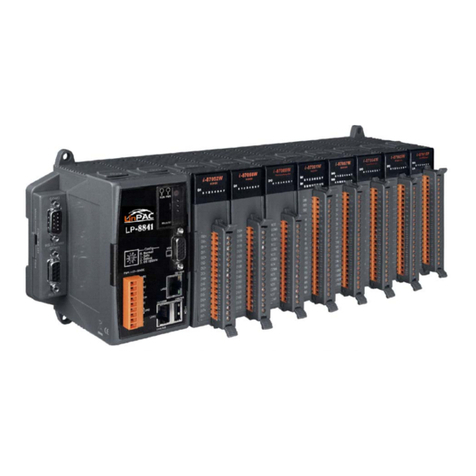
Tibbo WS1102 User manual

Programmable Hardware
Manual
WS1102
© 2021 Tibbo Technology Inc

2
Programmable Hardware Manual - WS1102 © 2021 Tibbo Technology Inc
Table of Contents
WS1102 Programmable Wireless RS232/422/485 Controller 3
Power Arrangement .................................................................................................................. 7
Serial Port .................................................................................................................................. 7
Definition of RS422 and RS485 Modes .......................................................................................... 10
Flash and EEPROM Memory .................................................................................................... 10
Buzzer ....................................................................................................................................... 11
Built-in Wi-Fi and BLE .............................................................................................................. 12
LED Bar ..................................................................................................................................... 12
DIN Rail and Wall Mounting Plates ........................................................................................ 13
Status LEDs (LED Control Lines) ............................................................................................. 15
Federal Communications Commission (FCC) Statement ..................................................... 16
Online Documentation ........................................................................................................... 16

3
Programmable Hardware Manual - WS1102 © 2021 Tibbo Technology Inc
WS1102 Programmable Wireless RS232/422/485 Controller
WS1102 Programmable Wireless RS232/422/485
Controller
Introduction
The WS1102 is a compact Tibbo BASIC/C-programmable wireless controller equipped with an
RS232/422/485 serial port. The product targets serial-over-IP (SoI) and serial control
applications.
This cloud-native device incorporates Wi-Fi (802.11a/b/g/n over 2.4GHz/5GHz) and Bluetooth
Low Energy (BLE) interfaces that introduce several new features, such as Wi-Fi auto-connects,
wireless debugging, over-the-air (OTA) updates, and Transport Layer Security (TLS) support. As

4
Programmable Hardware Manual - WS1102 © 2021 Tibbo Technology Inc
WS1102 Programmable Wireless RS232/422/485 Controller
a vendor-agnostic product, it can communicate with Microsoft Azure, Google Cloud, Amazon
Web Services (AWS), and virtually any other cloud services provider.
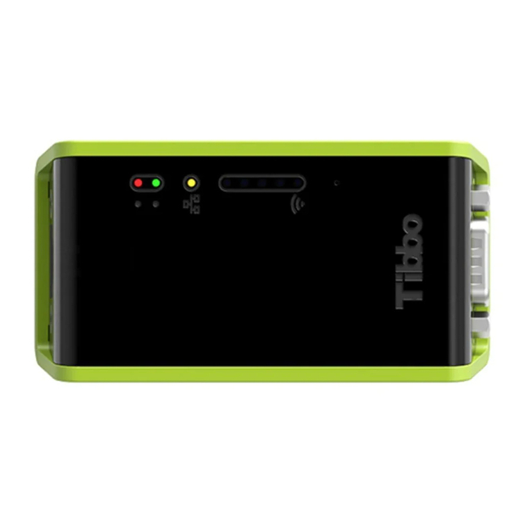
There are eight LEDs on the device's front: green and red main status LEDs, a yellow access
point association (link) LED, and five blue LEDs, which can be used for Wi-Fi signal strength
indication or other purposes. A buzzer is provided as well.
Each WS1102 is supplied with a DIN rail and wall mounting plates.
The WS1102 comes preloaded with a full-featured Serial-over-IP (SoI) application that turns the
WS1102 into a powerful serial-over-IP (SoI) device (a.k.a. a "device server"). A versatile Modbus
Gateway application is also available.
Hardware Features
§
Powered by Tibbo OS (TiOS)
§
Stores up to two compiled Tibbo BASIC/C binaries (apps)(1)
oA Device Configuration Block (DCB)(2) defines which of the two apps normally runs on
power-up
oForced launch of APP0 through the MD button
§
Wi-Fi interface (802.11a/b/g/n)
oControlled via a simple-to-use, yet sophisticated API
oTLS1.2 with RSA-2048 cryptosystem(3)
oOptional "autoconnect" — automatic association with a designated Wi-Fi network as
defined by the DCB(2)
oOptional debugging of Tibbo BASIC/C applications via the Wi-Fi interface(4)
§
Bluetooth Low Energy (BLE 4.2)
oControlled via a simple-to-use, yet sophisticated API
oCan access the DCB via a new, integrated console(2)
§
Internal Wi-Fi/BLE antenna
§
RS232/422/485 port on a DB9M connector
oPort modes are software-selectable
oTX, RX, RTS, CTS, DTR(5), and DSR(5) lines
oBaudrates of up to 921,600bps
oNone/even/odd/mark/space parity modes
o7 or 8 bits/character
oRTS/CTS and XON/XOFF flow control

5
Programmable Hardware Manual - WS1102 © 2021 Tibbo Technology Inc
WS1102 Programmable Wireless RS232/422/485 Controller
§
Built-in buzzer
§
RTC (no backup battery)
§
58KB SRAM for Tibbo BASIC/C variables and data
§
4MB flash for code storage
oSystem files and TiOS occupy a combined 2,408KB
o1,688KB available for storing up to two app binaries
§
Additional 4MB flash for the hardened fault-tolerant file system
§
2048-byte EEPROM for data storage
§
Eight LEDs
oGreen and red main status LEDs
oYellow access point association (link) LED
oFive blue LEDs (for Wi-Fi signal strength indication, etc.)
§
Power: 12VDC (9 ~ 18V)(6)
oCurrent consumption at idle of 55mA ~ 65mA @12VDC
oCurrent consumption when in operation (transferring data) of ~80mA @12VDC with spikes
of up to 130mA
§
Dimensions (LxWxH): 90 x 48 x 25mm
§
Operating temperature range: –40°C to +85°C(6)(7)
§
Firmware and compiled Tibbo BASIC/C apps can be updated via:
oSerial port
oWi-Fi interface
oBluetooth Low Energy (BLE) interface
§
Tibbo BASIC/C applications can be debugged via Wi-Fi(4) or serial port(5)
§
Supplied with an SoI app preloaded
§
Supplied with an SoI companion app preloaded
oThe app allows editing of the DCB from the L.U.I.S. smartphone app (available for iOS and
Android)
oUsers are free to modify the app for additional functionality
1. Although two independent Tibbo BASIC/C compiled binaries (apps) can be stored in the WS1102's
flash memory, only one can run at a time.
2. Several of the WS1102's configuration parameters are stored in the DCB, which is accessible via a
new integrated console. Our BLE Terminal web app leverages the Web Bluetooth API (compatible

6
Programmable Hardware Manual - WS1102 © 2021 Tibbo Technology Inc
WS1102 Programmable Wireless RS232/422/485 Controller
with the Chrome, Chromium, Edge, and Opera web browsers) to connect to the WS1102's console.
Configuration properties can also be read and set through Tibbo BASIC/C code.
3. TLS is supported on a single outgoing TCP connection.
4. To enable Wi-Fi debugging, you must enable autoconnect — automatic association with a
designated Wi-Fi network. This can be accomplished via the integrated BLE console or in code.
5. The TX and RX line of the debugging UART are connected to the DTR and DSR lines of the serial
port. When the serial debugging is enabled, these lines cease functioning as the DTR and DSR
lines. To avoid occupying the DTR and DSR lines for debugging, use wireless debugging instead.
The debug mode can be selected via the integrated BLE console or in code.
6. The WS1102 is compliant with the IEC/EN 62368-1 safety standard in the –40°C to +85°C range.
To maintain this compliance in the field, use an external DC power source outputting 0.5A @
9VDC ~ 18VDC (less than 15W) that is also IEC/EN 62368-1 certified and can operate in the –40°C
to +85°C range.
7. Tested according to procedures I, II, and III of MIL-STD-810H Method 501.7 and MIL-STD-810H
Method 502.7.
Programming features
·
Platform objects:
oadc — provides access to three ADC channels
obeep — generates buzzer patterns(1)
obt — in charge of the BLE (Bluetooth Low Energy) interface(1)
obutton — monitors the MD (setup) line
ofd — manages the flash memory file system and direct sector access(1)
oio — handles I/O lines, ports, and interrupts
okp — works with matrix and binary keypads
opat — "plays" patterns on up to five LED pairs
oppp — accesses the Internet over a serial modem (GPRS, etc.)
opwm — handles pulse-width modulation channels(1)
oromfile — facilitates access to resource files (fixed data)
ortc — keeps track of date and time
oser — controls the serial ports (UART, Wiegand, clock/data modes)(1)
osock — socket comms (up to 32 UDP, TCP, and HTTP sessions) and support for TLS(2)
ossi — controls serial synchronous interface channels (SPI, I²C)
ostor — provides access to the EEPROM

7
Programmable Hardware Manual - WS1102 © 2021 Tibbo Technology Inc
WS1102 Programmable Wireless RS232/422/485 Controller
osys — in charge of general device functionality(1)
owln — handles the Wi-Fi interface1
·
Function groups: String functions, trigonometric functions, date/time conversion functions,
encryption/hash calculation functions, and more
·
Variable Types: Byte, char, integer (word), short, dword, long, real, and string, as well as user-
defined arrays and structures
Notes:
1. These platform objects are either new or have new features (as compared to the EM2000).
2. TLS1.2 with RSA-2048 cryptosystem, supported on a single outgoing TCP connection.
Power Arrangement
The WS1102 can only be powered through the power jack.
The power jack accepts "small" power connectors with a 3.5mm diameter.
On the power jack, the ground is "on the outside," as shown in the figure below.
Serial Port
The WS1102 features a multimode RS232/422/485 port. Physically, the port is implemented as
a single DB9M connector.
Note: See Definition of RS422 and RS485 Modes for information on how these modes are
implemented on the WS1102.
Port pin assignment
In the RS232 mode, the serial port of the WS1102 has three output and three input lines. In the
RS422 mode, you get two output and two input line pairs. The RS485 mode offers one output
line pair and one input line pair. These are not independent — they operate in the half-duplex
mode.
The serial port of the WS1102 is controlled via the ser. object (see the TIDE, TiOS, Tibbo BASIC,
and Tibbo C Manual).

8
Programmable Hardware Manual - WS1102 © 2021 Tibbo Technology Inc
WS1102 Programmable Wireless RS232/422/485 Controller
RS232
RS422***
RS485***
#1
<No connection>
RTS– (output)
<No connection>
#2
RX (input)
RX– (input)
RX– (input)
#3
TX (output)
TX+ (output)
TX+ (output)
#4
DTR (output)*
TX– (output)
TX– (output)
#5
Ground
Ground
Ground
#6
DSR (input)**
RX+ (input)
RX+ (input)
#7
RTS (output)
RTS+ (output)
<No connection>
#8
CTS (input)
CTS+ (input)
<No connection>
#9
<No connection>
CTS– (input)
<No connection>
* When serial debugging is enabled, this line ceases to work as the DTR line of the serial port and
becomes the TX line of the debug serial port.
** When serial debugging is enabled, this line ceases to work as the DSR line of the serial port and
becomes the RX line of the debug serial port.
*** Serial debugging is not possible in these modes.
Selecting the serial port mode
On the WS1102, the serial port mode is controlled via Microchip's MCP23008 I/O expander IC.
The I²C interface of this IC is connected to GPIO5 and GPIO6 of the WS1102's CPU, as shown in
the diagram below.

9
Programmable Hardware Manual - WS1102 © 2021 Tibbo Technology Inc
WS1102 Programmable Wireless RS232/422/485 Controller
Use the ssi. object (see the TIDE, TiOS, Tibbo BASIC, and Tibbo C Manual) to communicate with
the MCP23008. To select the desired serial port mode, set the state of the I/O expander's lines
GP5 and GP6 as shown in the table below (these lines are not to be confused with GPIO5 and
GPIO6, which are the CPU lines driving the I²C interface of the I/O expander). Both GP5 and
GP6 should be configured as outputs.
Serial port
mode
GP5
GP6
RS232
HIGH
LOW
RS422
HIGH
HIGH
RS485
LOW
HIGH
Direction control in the RS485 mode

10
Programmable Hardware Manual - WS1102 © 2021 Tibbo Technology Inc
WS1102 Programmable Wireless RS232/422/485 Controller
In the RS485 mode, which is half-duplex, the PL_IO_NUM_3_INT1 GPIO line acts as the direction
control line. The line must be configured as an output.
Direction
PL_IO_NUM_3_INT1
Output
HIGH
Input
LOW
Definition of RS422 and RS485 Modes
To avoid any misunderstanding of what the RS422 and RS485 modes are, let's clarify that the
term "RS422 mode" refers to a full-duplex differential signaling interface with at least RX and
TX signals, and possibly with CTS and RTS signals. Each signal is carried by a pair of "+" and "–"
lines.
The term "RS485 mode" refers to a half-duplex differential signaling interface with RX and TX
lines, where each signal is also carried by a pair of "+" and "–" lines. The RTS line of the serial
port is used (within the serial controller) to control the direction, so TX and RX lines can be
combined (externally) to form a two-wire bus that carries data in both directions. On a physical
signal level (voltages, etc.), there is no difference between the RS422 and RS485 modes — they
are implemented in the same way.
The RS422 and RS485 modes typically require termination circuits. No such circuits are
provided within the WS1102. A simple 120Ω resistor (added externally) is sufficient to
terminate one "+/–" pair properly.
Flash and EEPROM Memory
These are the three types of flash memory that you will encounter on the WS1102:
·
Unified flash memory – stores the TiOS firmware, compiled Tibbo BASIC/C app, and,
optionally, the flash disk. All flash space not occupied by TiOS is available to the compiled
Tibbo BASIC/C app. All flash space left over from TiOS and the app can be formatted as a
fault-tolerant flash disk. The flash disk is accessible through the fd. object (see the TIDE, TiOS,
Tibbo BASIC, and Tibbo C Manual).
·
Program flash memory — stores the TiOS firmware and compiled Tibbo BASIC app(s). All
flash space not occupied by TiOS is available to the compiled Tibbo BASIC/C app.
·
Data flash memory — the entire memory space can be formatted as a fault-tolerant flash
disk. The flash disk is accessible through the fd. object.
In addition, the WS1102 is equipped with EEPROM memory. A small area at the bottom of the
EEPROM is occupied by the Special Configuration Section (SCS) that stores the device's MAC(s)
and password. The rest of the EEPROM is available to Tibbo BASIC/C applications. The EEPROM
is accessible through the stor. object (see the TIDE, TiOS, Tibbo BASIC, and Tibbo C Manual).

11
Programmable Hardware Manual - WS1102 © 2021 Tibbo Technology Inc
WS1102 Programmable Wireless RS232/422/485 Controller
Unified flash
memory
(available app/disk
space)
Program flash
memory
(available app
space)
Data flash memory
EEPROM
(space occupied by
the SCS)
---
4MB (4,048KB)
4MB (4,048KB)
2KB (28 bytes)
On the advice of one of our customers, we are giving you the following reminder: Like
all other EEPROMs on the market, EEPROM ICs used in Tibbo devices allow for a limited
number of write cycles. As the Wikipedia article on EEPROM states, the EEPROM "... has a
limited life for erasing and reprogramming, now reaching a million operations in modern EEPROMs.
In an EEPROM that is frequently reprogrammed while the computer is in use, the life of the EEPROM
is an important design consideration." When planning to use the stor. object, please carefully
consider if the planned mode of EEPROM use will allow the EEPROM to work reliably through
the entire projected life of your product.
Like all other flash memory devices on the market, flash ICs used in Tibbo products only allow
for a limited number of write cycles. As the Wikipedia article on flash memory explains,
modern flash ICs still suffer from comparatively low write endurance. In Tibbo devices, this
endurance is about 100,000 write cycles per sector. When you are using the flash memory for
file storage, the fd. object employs sector wear leveling to maximize the life of the flash IC (but
the life still remains limited). If your application employs direct sector access, then it is your job
to plan the application around the life limitations of the flash memory. For data that changes
often, consider using the EEPROM instead — EEPROMs have much better endurance.
Buzzer
The buzzer is on the WS1102. The buzzer's center frequency is 2,750Hz.
Your application can control the buzzer through the "beeper" (beep.) object (see the TIDE, TiOS,
Tibbo BASIC, and Tibbo C Manual).
The buzzer is connected to the PL_IO_NUM_9 GPIO line. The recommended value for the
beep.frequency property is 2750.

12
Programmable Hardware Manual - WS1102 © 2021 Tibbo Technology Inc
WS1102 Programmable Wireless RS232/422/485 Controller
Built-in Wi-Fi and BLE
The WS1102 features built-in Wi-Fi and BLE interfaces. These interfaces are accessible via wln.
and bt. objects.
The expanded wln. object supports automatic association with a designated network, wireless
debugging, and Transport Layer Security (TLS) 1.2 encryption.
LED Bar
The WS1102 features an LED bar comprised of five blue LEDs. The bar can be used for signal
strength indication and other purposes.
Note: The green, red, and yellow status LEDs are described in the Status LEDs topic.
On this wireless controller, the LEDs are controlled via Microchip's MCP23008 I/O expander IC.
The I²C interface of this IC is connected to GPIO lines 5 and 6 of the WS1102's CPU, as shown in
the diagram below.

13
Programmable Hardware Manual - WS1102 © 2021 Tibbo Technology Inc
WS1102 Programmable Wireless RS232/422/485 Controller
Use the ssi. object (see the TIDE, TiOS, Tibbo BASIC, and Tibbo C Manual) to communicate with
the MCP23008.
To turn an LED on, configure the corresponding line of the IC as an output and set it LOW.
Refer to the MCP23008 datasheet for information on how to achieve this.
The WS1102 is fully supported by CODY, Tibbo's project code wizard. CODY can generate the
scaffolding for your WS1102 projects, including the code to control the LED bar.
DIN Rail and Wall Mounting Plates
The WS1102 ships with two mounting plates — one for installation on a DIN rail and one for
mounting on a wall.
Both plates are secured onto the device using two screws (included with each device).

14
Programmable Hardware Manual - WS1102 © 2021 Tibbo Technology Inc
WS1102 Programmable Wireless RS232/422/485 Controller
The wall mounting plate can be used to mount the WS1102 on a wall in a semi-permanent or
permanent manner. The diagram below shows the installation footprint.

15
Programmable Hardware Manual - WS1102 © 2021 Tibbo Technology Inc
WS1102 Programmable Wireless RS232/422/485 Controller
Status LEDs (LED Control Lines)
Every Tibbo device has two status LEDs — green and yellow — that indicate various device
modes and states. We refer to these LEDs as "Status Green" (SG) and "Status Red" (SR). These
LEDs are used:
·
By the Monitor/Loader (M/L)
·
By Tibbo OS (TiOS):
oWhen a Tibbo BASIC/C app is not running, these LEDs show the current state of the device
oWhen a Tibbo BASIC/C app is running, the status LEDs are under the app's control through
the pat. object (see the TIDE, TiOS, Tibbo BASIC, and Tibbo C Manual)
Many Tibbo programmable devices also have a "Status Yellow" (SY) LED. This LED is commonly
used to indicate that a network link has been established, but it serves other functions in
certain situations.

16
Programmable Hardware Manual - WS1102 © 2021 Tibbo Technology Inc
WS1102 Programmable Wireless RS232/422/485 Controller
Federal Communications Commission (FCC) Statement
You are cautioned that changes or modifications not expressly approved by the part
responsible for compliance could void the user’s authority to operate the equipment.
This device complies with Part 15 of the FCC Rules. Operation is subject to the following two
conditions:
1) this device may not cause harmful interference, and
2) this device must accept any interference received, including interference that may cause
undesired operation of the device.
This equipment has been tested and found to comply with the limits for a Class B digital device,
pursuant to part 15 of the FCC rules. These limits are designed to provide reasonable
protection against harmful interference in a residential installation. This equipment generates,
uses and can radiate radio frequency energy and, if not installed and used in accordance with
the instructions, may cause harmful interference to radio communications. However, there is
no guarantee that interference will not occur in a particular installation. If this equipment does
cause harmful interference to radio or television reception, which can be determined by
turning the equipment off and on, the user is encouraged to try to correct the interference by
one or more of the following measures:
-Reorient or relocate the receiving antenna.
-Increase the separation between the equipment and receiver.
-Connect the equipment into an outlet on a circuit different from that to which the receiver is
connected.
-Consult the dealer or an experienced radio/TV technician for help.
FCC RF Radiation Exposure Statement:
This equipment complies with FCC radiation exposure limits set forth for an uncontrolled
environment. This equipment should be installed and operated with minimum distance 20cm
between the radiator & your body. This transmitter must not be co-located or operating in
conjunction with any other antenna or transmitter.
Online Documentation
For the most up-to-date documentation of the WS1102, please refer to Tibbo's online
documentation.
Table of contents
Other Tibbo Controllers manuals
