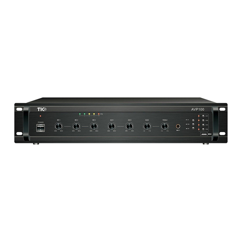
TIC AVP700 User manual

CAUTION:
TO PREVENT THE RISK OF ELECTRIC SHOCK, DO NOT REMOVE ANY FRONT/BACK COVERS OR
PANELS. NO USER-SERVICEABLE PARTS INSIDE. REFER SERVICING TO QUALIFIED PERSONNEL.
The lightning flash with an arrowhead symbol, within an equilateral triangle, is intended
to alert the user to the presence of uninsulated “dangerous voltage” within the product’s
enclosure that may be of sufficient magnitude to constitute a risk of electric shock to
persons.
The exclamation point within an equilateral triangle is intended to alert the user to the
presence of important operating and maintenance (servicing) instructions in the
literature accompanying the product.
RISK OF ELECTRIC SHOCK
DO NOT OPEN
WARNING:
TO REDUCE THE RISK OF FIRE OR ELECTRIC SHOCK, DO NOT EXPOSE THIS APPARATUS TO RAIN
OR MOISTURE.
SOUND WARNING:
Avoid hearing damage by establishing safe listening volumes. Listening to this product at high volumes
or for extended time periods may cause permanent hearing loss. Protect your hearing by establishing
safe volumes. Start with the volume setting control at its lowest setting. Slowly increase the volume until
you can hear it comfortably and clearly without distortion. Reduce the volume or stop listening if you
experience ringing in your ears or any discomfort. Consult with a physician if needed.
AVP700
Instruction Manual
680W 6-Zone 70v/100v/4-16Ω
Commerical Mixer Amplifer
POW ER
CH4 C H5 CH6 EM ER BEL L
CH1 C H2 CH3 CH IME
MIC1 MIC2M IC3AUX1 AU X2BASS TRE BLE
VOLUM E VOLUM E
MIN MAXMIN MAX -10 +10-10 +10MIN MAXMIN MAXMIN MAX
MIC1
AVP700

01 02
IMPORTANT SAFETY INSTRUCTIONS:
WARNING: Improper use may potentially cause injury, loss of property and
/or death.
1. Read these instructions.
2. Follow all instructions and heed all warnings.
3. Keep this instruction manual in a safe place for future reference.
4. Do not use this apparatus near water.
5. Clean only with a dry cloth.
6. Do not install this apparatus near any heat sources such as radiators, heat
registers, stoves or other apparatus (including amplifiers) that produce heat.
7. Do not block any ventilation openings. Install this apparatus in accordance with the
manufacturer’s instructions.
8. Do not defeat the safety purpose of the polarized or grounding-type plug. A
polarized plug has two blades with one wider than the other. A ground-type plug has
two blades and a third grounding prong. The wide blade or the third prong is provided
for your safety. If the provided plug does not fit into your outlet, consult an electrician
for replacement of the obsolete outlet.
9. Protect the power cord from being walked on or pinched, particularly at plugs,
convenience receptacles and the point where they exit from the apparatus.
10. Use only attachments and accessories specified by the manufacturer.
11. Unplug this apparatus during lightning storms or when unused for long periods of
time.
12. Refer all servicing to qualified service personnel. Servicing is required when the
apparatus has been damaged in any way, such as when the power supply cord or
plug is damaged, liquid has been spilled or objects have fallen into the apparatus, or
the apparatus had been exposed to rain or moisture, does not operate normally or
has been dropped.
13. Do not expose this apparatus to dripping or splashing, and ensure that no objects
filled with liquids, such as vases, are placed on the apparatus.
14. To disconnect this apparatus from the AC mains completely, disconnect the
power supply cord plug from the AC receptacle.
15. The mains plug of the power supply cord shall remain readily operable.
16. Do not expose batteries to excessive heat such as sunshine, fire, or the like.
17. This is not a children’s product and is not intended for use by children under 14
years old.
18. Do not place heavy objects on the apparatus.
19. Only install this apparatus in an upright position at a location that is stable and
well-ventilated.
20. If any abnormal conditions are found during use, please turn off the apparatus
and disconnect the power supply immediately. Contact your nearest dealer and do
WARRANTY:
TIC offers a limited one-year full parts and labor warranty for all of our new products.
Please visit TIC’s warranty page (http://www.ticcorp.com/warranty/ ) for detail to our
latest warranty policy.
TIC Audio Inc. All rights reserved. The TIC logo is a trademark of TIC Audio Inc,
registered in the United States.
Features, specifications, and appearance are subject to change without notice.
For more information, please visit our website: www.ticcorp.com.

03 04
AVP700
Overview:
Features:
Usage:
TIC AVP-700 is a commerical-grade class A/B power amplifer with constant-
voltage options.
• 680 watt total power
• Standard 2U chassis
• 6-zone 70v ouput
• 70v/100v/8Ω single line output
• 3 microphones input, 2 AUX audio input, 1 audio output
• EQ with treble and bass adjustment
• Automatic thermal, overload, circuit protection
• Distortion/clipping indicators
• Built-in siren, chime, and bell function
Designed for broadcasting audio via a constant-voltage distributed sound system or
high-impedance loudspeaker system. Perfect for public address (PA) and background
music.
Table of Content
1. Safety Instructions.................................................................................1
2. Warranty & Company Info.......................................................................2
3. Overview..............................................................................................4
4. Front Panel...........................................................................................5
5. Rear Panel............................................................................................6
6. Operation...........................................................................................7-9
7. Troubleshooting...................................................................................10
8. Input/output Connection Diagram..........................................................11
9. System Schematics..............................................................................12
10. Specifications....................................................................................13
11. Dimensions........................................................................................14

05 06
AUX 2 volume control
10
11 Bass EQ control
12 Treble EQ control
13 Power, protection mode, signal, and clipping indictator
14 Bell button
Mic 3 volume control
8
AUX 1 volume control
9
Power switch
1
Zone 1-6 switches & indictators
2
Emergency Siren button
3
Chime button
4
Mic 1 (priority) input
5
Mic 2 volume control
7
Mic 1 volume control
6
PO WE R
1
CH 4 CH 5 C H6 EM ER BEL L
CH 1 CH 2 C H3 CH IM E
2
56 7 89 10 11 12 13
3 4
14
MIC1 MI C2MIC3AUX1 AUX2BA SS TRE BLE
VOLU ME VOLU ME
MIN MAXMIN MAX -10 +10-10 +10MIN MAXMIN MA XMIN MAX
MIC1
COM CO M COM COM C OM COM CO M COM COM
CH6 CH 5 CH4 CH3 C H2 CH1 10 0V 70 V 4-16 Ω
6
10
45
3
21
7 8 9
6Zone 1-4 terminals (70v)
5Mic 2 input
4Mic 3 input
2AUX 1 input
3AUX 2 input
1LINE output
10 Power cord
7100v output terminal
870v output terminal
94-16Ω output terminal
AVP700
Rear PanelFront panel

07 08
Option 1: 6-zone 70v output
*You can use any of combination of the 6 channels.
COM COM COM COM COM COM COM COM COM
CH6 CH5 CH4 CH3 CH2 CH1 100V 70V 4-1 6Ω
COM COM COM COM COM COM COM COM COM
CH6 CH5 CH4 CH3 CH2 CH1 100V 70V 4-16Ω
COM COM COM COM COM COM COM COM COM
CH6 CH5 CH4 CH3 CH2 CH1 100V 70V 4-16Ω
COM COM COM COM COM COM COM COM COM
CH6 CH5 CH4 CH3 CH2 CH1 100V 70V 4-16Ω
AVP700 can be set up in one of four options. Utilizing multiple options simutaneously may
cause issues and damage to the amplifier. Please ensure the polarity of speaker wires are
correctly matched and connected.
Operation:
Option 2: Single 100v output
Option 3: Single 70v output
Option 4: 4-16Ω output
Note:
1. Please make sure that the power is turned off during speaker installation. When the power is on,
there may be a risk of electric shock.
2. Please ensure the sum of the power and impedance load of the speakers connected does not
exceed the specified range of the amplifier. Ideally, the total power load doesn't exceed 80% of the
rated output power of the amplifier.

09 10
Operation instructions:
Step-by-Step Instruction:
A. Connecting loudspeakers
1. Ensure power switch is at the OFF position.
2. Connect power cord to power soruce outlet.
3. Determine and prepare the appropriate speaker wire (gauge, insulation type, length).
4. Connect speaker to the appropriate wiring terminals, as instructed in the previous section.
5. Turn down all volume knobs and then turn on power switch.
B. Audio device input
1. Turn down volume before plugging in a new input device.
2. Adjust volume to the desired level.
3. When MIC1 input is plugged in, other input channels will be automatically muted. Only plug in
MIC1 when actively utilized.
C. Power down
1. Turn down the volume knob before turning off the amplifier.
2. After turning off the amplifier, please wait at least 5 seconds before turning on again.
Switching the power on and off in quick sucession may cause device failure.
Troubleshooting
Symptom Cause & Solution
1. Power does not turn on. 1. Power source is disconnected or cut.
2. Protection mode is activated.
4. Volume is low.
5. Sound is distorted. 1. Input level of microphone or external device is too high.
2. Volume level is too high.
2.No sound output.
1. No power is connected.
2. Fuse is blown and needs to be replaced.
3. Volume is turned off completely.
4. No active input.
5. MIC1 (priority) is plugged in but inactive.
6. USB device is plugged in but no MP3 track is found.
3. Sound suddenly stops or is
intermittent during playback.
1. Protection mode is activated due to overheating.
Please wait a few minutes to restart.
2. Poor or broken wire connection.
1. A high-impedance loudspeaker (4-16Ω) is connected to
a low-impedance (70v/100v) output.
2. MIC1 is plugged in but inactive.
3. Volume needs to be turned up.

COM C OM COM C OM COM C OM COM C OM COM
CH6 C H5 CH4 C H3 CH2 C H1 100 V 70V 4-16Ω
11 12
6-zone 70v terminals
Connection Diagram
Amplifier
Protective circuitry
LED display
Fan control
Loudspeaker
LINE audio out
CP MP3 Play audio input
External audio device input (AUX)
100v/70v/4-16Ω terminals
AC power cord

13 14
Specifications
Output Power 680W
Model AVP700
Output Terminals 6-zone 70v, 4-16Ω, 70v, 100v
Input Sensitivity
Mic 1-3: 5mV/600Ω via unbalanced 1/4"" inputs
AUX 1-2: 350mV/ 10kΩ via unbalanced RCA inputs"
AUX Output Sensitivity &
Impedance 1000mV/470Ω via unbalanced RCA ouput
EQ Bass: ±10dB @ 100Hz; Treble: ±10dB @ 10kHz
Frequency Response 80-16kHz
Channel Crosstalk 50dB (MIC1 takes priority over all other inputs)
Signal-to-Noise Ratio Mic 1-3: 66dB or better
AUX 1-2: 80dB or better
THD less than 0.5% (at 1kHz, typical)
Cooling dynamic fan cooling
Protection Modes thermal overheating, overload, short-circuit
AC Power 100-130V/50Hz
Power Consumption 800W
Weight 34 pounds
Dimension 19.1" w x 15" d x 3.5" h
Dimensions
To keep the amplifier properly ventilated, a space of at least 4" should be cleared around the machine in
order to provide enough air circulation and prevent overheating.
4" 4"
4"
3.5"
19.1"
4.3"
POWE R
CH4 CH 5 CH 6 EME R BE LL
CH1 CH 2 CH 3 CHI ME
MIC1 MIC2MI C3AUX1 AUX2BAS S TREBLE
VOLUME V OLUME
MIN MAXMIN MAX -10 +10-10 +10MIN MAXMIN MAXMIN MAX
MIC1
AVP7 00
POW ER
CH4 C H5 CH 6 E MER B ELL
CH1 C H2 CH 3 C HIME
MIC1 MIC2M IC3AUX1 AU X2BASS TR EBLE
VOLUM E VOLUM E
MIN MAXMIN MAX -10 +10-10 +10MIN MAXMIN MAXMIN MAX
MIC1
AVP700
437
88
COM COM C OM COM COM C OM COM COM C OM
CH6 CH5 C H4 CH3 CH2 C H1 100V 70V 4-1 6Ω
This manual suits for next models
1
Table of contents
Other TIC Amplifier manuals
