TIDELAND Nova-65 SC User manual

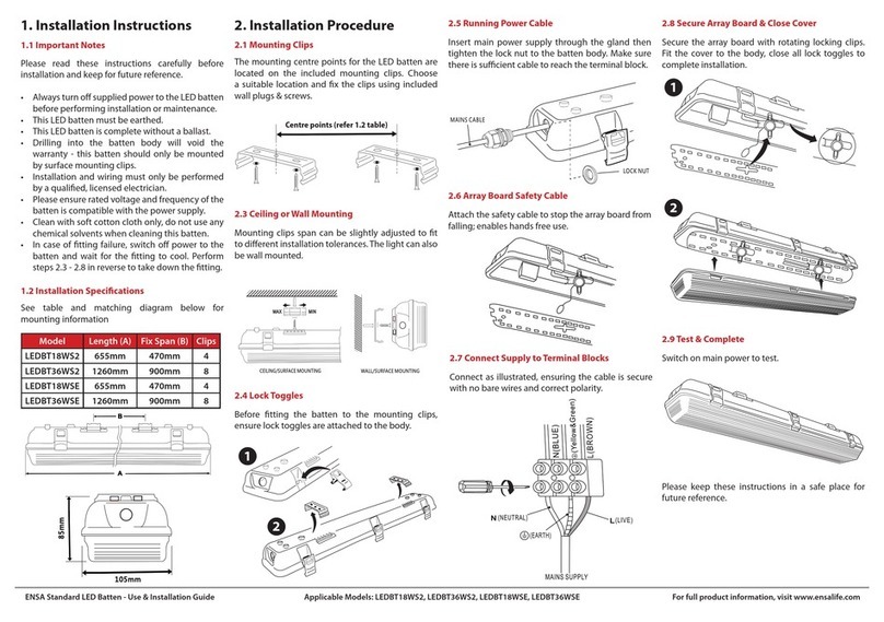
Tideland Signal Corp.
Featuring Aids to NavigationProducts
OPERATION MANUAL
NOVA-65 SC
011.1258-00
Alfredo Dominguez
Paul Mueller
Larry Mitschke
Engineering Mgr.
Project Engr.
Checker
B
0276
UPDATED TO NEW FORMAT
15JUNE16
RBT
A
----
RELEASED FOR PRODUCTION
19JAN12
BO
Rev
ECO
Description
Date
By

MAINTENANCE AND OPERATION MANUAL
NOVA-65 SC/0111258-00
TIDELAND SIGNAL
HEADQUARTERS (Houston, TX)
TEL + 1 713-681-6101
FAX + 1 713-681-6233
EMAIL us-sales@tidelandsignal.com
TIDELAND SIGNAL (Nova Scotia)
DSS Marine Incorporated
TEL + 1 844 843 3526
FAX + 1 613-680-7418
EMAIL canada-sa[email protected]
TIDELAND SIGNAL (Burgess Hill, UK)
TEL + 44 (0) 1444-872240
FAX + 44 (0) 1444-872241
EMAIL emea-sales@tidelandsignal.com
TIDELAND SIGNAL (Dubai, UAE)
TEL + 971 (0) 4-885-5842
FAX + 971 (0) 4-885-7352
EMAIL emea-sales@tidelandsignal.com
TIDELAND SIGNAL (Singapore)
TEL + 65 6333-0078
FAX + 65 6333-0079
EMAIL asia-sa[email protected]
TIDELAND SIGNAL (China)
TEL + 86 (0) 21- 1380 101 4639
FAX + 86 (0) 21-3868-8087
EMAIL asia-sa[email protected]
WEBSITE: www.tidelandsignal.com

MAINTENANCE AND OPERATION MANUAL
NOVA-65 SC/0111258-00
TABLE OF CONTENTS
1.0 OVERVIEW........................................................................................................................ ..1
1.1 Features ............................................................................................................................2
1.2 Specifications ....................................................................................................................2
1.3 Technical...........................................................................................................................3
1.3.1 Electrical.....................................................................................................................3
1.3.2 Operation Modes........................................................................................................7
2.0 INSTALLATION ................................................................................................................. 10
2.1 Unpacking........................................................................................................................10
2.1.1 Packing List/Part Numbers ......................................................................................10
2.1.2 Testing the Unit........................................................................................................10
2.2 Mounting/Physical Installation.........................................................................................11
2.2.1 Mounting Hole Pattern .............................................................................................11
2.2.2 Installation................................................................................................................11
2.2.3 Changing Flash Code..............................................................................................12
2.3 Wiring ..............................................................................................................................13
3.0 OPERATION...................................................................................................................... 13
3.1 Safety...............................................................................................................................13
3.2 Configuration...................................................................................................................13
3.3 LED Power Configuration................................................................................................21
3.4 Configuring as Backup to a Rotating Beacon.................................................................22
3.5 GPS Options and Configuration......................................................................................25
4.0 maintenance....................................................................................................................... 26
4.1 Safety...............................................................................................................................26
4.2 Service.............................................................................................................................26
4.3 Disassembly/Reassembly...............................................................................................26
4.4 Moisture Protection .........................................................................................................29
4.5 Troubleshooting...............................................................................................................29
4.5.1 Mechanical Verification............................................................................................29
4.5.2 Configuration Verification.........................................................................................29
4.5.3 Testing the Nova-65 SC...........................................................................................29
4.5.4 Troubleshooting with SignalView™ .........................................................................30
5.0 Spare Parts ........................................................................................................................ 32

MAINTENANCE AND OPERATION MANUAL
NOVA-65 SC/0111258-00
LIST OF FIGURES
Figure 1 NOVA-65 SC .................................................................................................................... 1
Figure 2 General Arrangement....................................................................................................... 3
Figure 3 Block Diagram .................................................................................................................. 4
Figure 4 Sunswitch Diagram........................................................................................................... 5
Figure 5 Fail Terminal Diagram...................................................................................................... 7
Figure 6 Cut Off Diagram................................................................................................................ 8
Figure 7 Mounting Hole Dimensions ............................................................................................ 11
Figure 8 On/Off/Winter Charging Switch......................................................................................12
Figure 9 System Wiring Diagram (Cable access is optional)....................................................... 13
Figure 10 Internal Wiring Diagram................................................................................................ 14
Figure 11 Blanking Panel Diagram............................................................................................... 24
Figure 12 GPS Diagram................................................................................................................ 25
Figure 13 Exploded Diagram........................................................................................................ 27
Figure 14 Disassembly Diagram................................................................................................... 28
Figure 15: EPDM Gasket.............................................................................................................. 29
LIST OF TABLES
Table 1 S4 Address Table............................................................................................................ 16
Table 2 S4 Sequence Delay Table............................................................................................... 18
Table 3 Default Option Table........................................................................................................ 19
Table 4 Power Selection Table.....................................................................................................22
Table 5 S4 Function Table............................................................................................................ 23
Table 6 Rotation Period Table...................................................................................................... 24
SYMBOLS USED IN THIS MANUAL:
WARNING! Failure to heed a warning SHALL result in personnel injury or
equipment damage.
WARNING! Failure to heed this warning SHALL result in exposure to
dangerous voltage.
CAUTION! Failure to heed a caution MAY result in personnel injury or
equipment damage.
NOTE: Failure to heed a note may result in equipment or process fail

MAINTENANCE AND OPERATION MANUAL
NOVA-65 SC/0111258-00
Tideland Signal Page 1 of 32
0111258-00 Rev. B 16-Jun-16
1.0 OVERVIEW
The Nova-65 SC features unique and proprietaryopticswhichprovidea 360°beam at
5°, 10° or 20° vertical divergence. Utilizinga highly efficient compact lens, the Nova-
65 SC is engineered to utilize the advanced and cost-effective technology of LEDs.
Solar modules and high-grade batteries are housed in a compact self-contained
marine lantern, designed for low maintenance with a projected servicelifeof 10years
before any significant maintenance is needed. The 10° divergence lens is ideal for
fixed or floating aids to navigation while the 20° lens provides exceptional
performance on buoys. The 5° lens can be used to meet specific needs that require
a much longer range while still using a minimal amount of power.
The Nova-65 SC’s power efficiency provides superior performance in fixed or floating
aids to navigation applications.
Figure 1 NOVA-65 SC
Table of contents
Popular Lantern manuals by other brands

shada
shada 1000436 instruction manual
BEGA
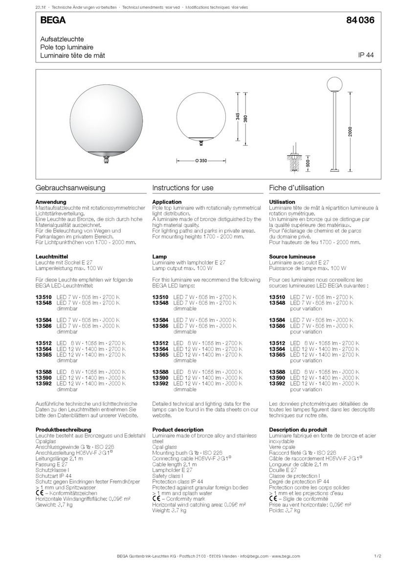
BEGA 84 036 Instructions for use
BEGA
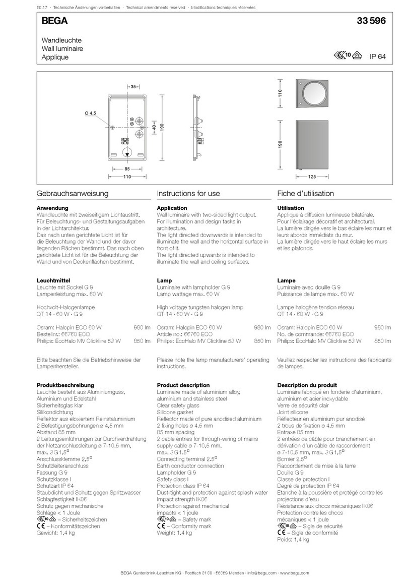
BEGA 33 596 Instructions for use

Dale Tiffany
Dale Tiffany GT701162 Assembly instructions

Wagan
Wagan Brite Nite Pop-Up USB Lantern user manual

Eaton
Eaton Crouse-Hinds Pauluhn DLLA M2 Series Installation & maintenance information
