Tides Marine SmartSeal TPS-BH-TE User manual
User Manual
Temperature Sensor System
®
SmartSeal

Congratulations on your purchase of the Tides Marine
SmartSeal® Temperature Sensor System. This manual will
describe how the system works, the various system components
and how to operate the system. Detailed information on
Installation can be found in the Installation / Specifications
Manual.
System Overview
The SmartSeal Temperature Sensor System is designed to
compliment Tides Marine’s SureSeal Shaft Seal Systems on
vessels with single or twin engines. Its purpose is to detect and
warn of various vessel conditions which could potentially lead to
shaft seal damage or failure. It is compatible with vessels which
utilize the NMEA 2000 communication protocol for connecting
marine electronics, sensors and display units to a backbone
network for centralized monitoring of various types of vessel
information. It is also designed to operate on non-NMEA 2000
equipped vessels as well on vessels with certain other networks
via a converter (e.g. NMEA 01830).
Functional Overview
The SmartSeal System is comprised of a number of components
designed to work with a wide range of vessel types and
installation needs. At the heart of the system is a Main Control
Unit which is located in the engine compartment. Connected to
this unit are temperature sensors for each shaft seal in use.
Remote Monitoring Units can be connected and placed in other
areas of the vessel as can a remote external siren. In operation,
temperature status data is displayed on both the Main and
Remote unit’s control panels. When connected to a vessel’s
NMEA 2000 onboard network, temperature data is also sent to the
main or auxiliary computer display. In the event that the
temperature of the shaft seal(s) or the engine compartment
exceeds the normal operating range limit, visible and audible
alerts are initiated so that corrective action can be taken.
2
Table Of Contents
External Siren.........................................................................5
System Operation:
Remote Unit............................................................................3-4
Shaft Seal Sensor...................................................................5
Powering.................................................................................6
Operating................................................................................6
Operating States:
Normal State...........................................................................7
Error Indications.....................................................................9
Troubleshooting.....................................................................10
Causes of Alerts......................................................................9
Self-Test Function...................................................................9
System Overview....................................................................2
Functional Overview...............................................................2
System Components:
Main Control Unit....................................................................3-4
Warning State.........................................................................7-8
Critical Alert State...................................................................8

Remote Monitoring Units (RMU)
The Remote Monitoring Units are display extensions of the Main Control Unit.
On larger vessels, one or more RMUs are typically installed in locations where
they can be easily monitored. To afford installation flexibility, two mounting
configurations are offered: Surface / Bulkhead mount (identical to the Main
Control Unit), and a panel mount design for installing into Consoles or Helm
Stations.
The RMU’s front panel display will have the same LED indicators and alarm
speaker as found on the Main Control Unit.
Main Control Unit
/ NMEA 2000
Connector
Temp. Status
Indicators
Onboard
Alarm
Speaker
Remote Unit,
Bulkhead Mount
Twin Engine
P/N TPS-RDBH
Remote Monitoring Unit,
Bulkhead Mount
Single Engine
P/N TPS-RSBH
Remote Unit Monitoring,
Panel Mount
Single Engine
P/N TPS-RSPN
Remote Monitoring Unit,
Panel Mount
Twin Engine
P/N TPS-RDPN
4
System Components
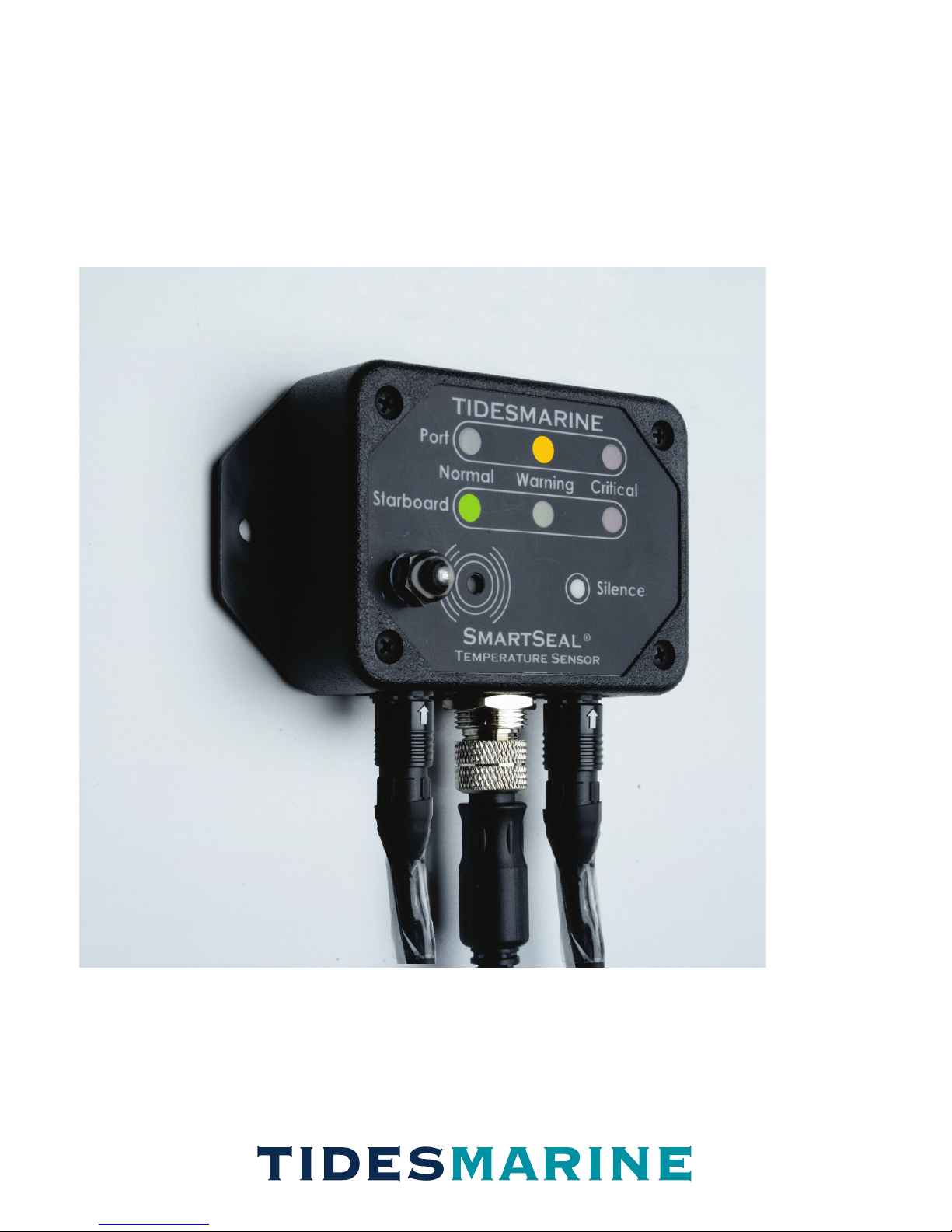
Main Control Unit (MCU)
Mounted in the engine compartment, the Main Control Unit contains a
microprocessor which is responsible for the systems operation.
The MCU front panel has an onboard audible alarm and silence
control, ambient temperature sensor and LED temperature status
indicators. There are single and twin engine models available. Both
models are identical in size and have flanges for surface mounting.
Units are ideally positioned on vertical surfaces/ bulkheads which are
both visually and physically accessible.
Each MCU has two types of connectors on the bottom of its enclosure.
The first is used to connect the shaft seal sensor, neutral safety switch
and optional remote siren. The second is used for connecting the
Remote Monitor Unit and 12VDC power source or to connect the
SmartSeal System to a NMEA 2000 network.
Main Control Units are IP66 rated (waterproof for heavy spray and brief
submersion)
Main Control Unit,
Bulkhead Mount
Twin Engine
P/N TPS-BH-TE
PORT Side
Harness
Connector
STBD. Side
Harness
Connector
Ambient Temp.
Sensor
Temp. Status
Indicators
Alarm/Siren
Control
Onboard
Alarm
Speaker
Remote Unit
/ NMEA 2000
Connector
Main Control Unit,
Bulkhead Mount
Single Engine
P/N TPS-BH-SE
3

Remote Monitoring Units (RMU)
The Remote Monitoring Units are display extensions of the Main Control Unit.
On larger vessels, one or more RMUs are typically installed in locations where
they can be easily monitored. To afford installation flexibility, two mounting
configurations are offered: Surface / Bulkhead mount (identical to the Main
Control Unit), and a panel mount design for installing into Consoles or Helm
Stations.
The RMU’s front panel display will have the same LED indicators and alarm
speaker as found on the Main Control Unit.
Main Control Unit
/ NMEA 2000
Connector
Temp. Status
Indicators
Onboard
Alarm
Speaker
Remote Unit,
Bulkhead Mount
Twin Engine
P/N TPS-RDBH
Remote Monitoring Unit,
Bulkhead Mount
Single Engine
P/N TPS-RSBH
Remote Unit Monitoring,
Panel Mount
Single Engine
P/N TPS-RSPN
Remote Monitoring Unit,
Panel Mount
Twin Engine
P/N TPS-RDPN
4
System Components
Main Control Unit (MCU)
Mounted in the engine compartment, the Main Control Unit contains a
microprocessor which is responsible for the systems operation.
The MCU front panel has an onboard audible alarm and silence
control, ambient temperature sensor and LED temperature status
indicators. There are single and twin engine models available. Both
models are identical in size and have flanges for surface mounting.
Units are ideally positioned on vertical surfaces/ bulkheads which are
both visually and physically accessible.
Each MCU has two types of connectors on the bottom of its enclosure.
The first is used to connect the shaft seal sensor, neutral safety switch
and optional remote siren. The second is used for connecting the
Remote Monitor Unit and 12VDC power source or to connect the
SmartSeal System to a NMEA 2000 network.
Main Control Units are IP66 rated (waterproof for heavy spray and brief
submersion)
Main Control Unit,
Bulkhead Mount
Twin Engine
P/N TPS-BH-TE
PORT Side
Harness
Connector
STBD. Side
Harness
Connector
Ambient Temp.
Sensor
Temp. Status
Indicators
Alarm/Siren
Control
Onboard
Alarm
Speaker
Remote Unit
/ NMEA 2000
Connector
Main Control Unit,
Bulkhead Mount
Single Engine
P/N TPS-BH-SE
3
Operation
System Power
The SmartSeal system operates on 12VDC (+/-3VDC).
The Main Control Unit and Remote Monitoring Units are connected to each
other using standard NMEA network hardware components. Use of this
hardware allows the SmartSeal system to be easily added to (and be
powered by) an existing NMEA 2000 network.
If no existing network is available, a suitable power source must be
connected (thus creating a private SmartSeal network). The system is
designed such that you can plug or unplug it from its network whether or not
it is powered.
Operating the System
The SmartSeal Temperature Sensor is an autonomous system. It
continuously monitors shaft seal temperature(s) and reports results as visual
and audible indications on the Main and Remote unit front panels. It also
broadcasts shaft seal and engine room temperature measurements on the
NMEA 2000 network for display on MFDs, etc.
Proper operation of the system is very simple:
If a WARNING or CRITICAL ALERT occurs, the condition must be
immediately resolved.
External Siren
The External Siren is an optional component which is typically installed on
larger vessels where engine rooms can be quite loud and are located some
distance from the main helm station. There are several options for the types of
sound the siren will emit which can be selected at the time of installation.
Siren
P/N SP-SS-SIREN
65
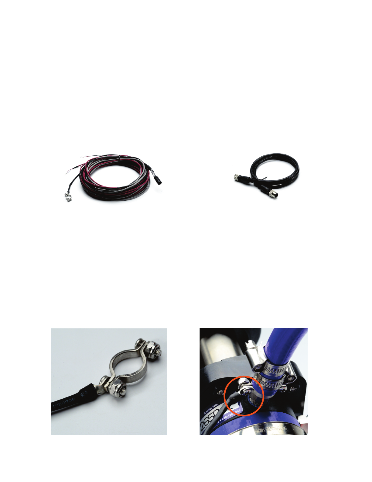
Cabling
The SmartSeal system uses two types of cabling to connect the various
components:
A custom harness is supplied for connecting the Shaft Seal sensor, Neutral
Safety Switch and External Siren to the Main control unit.
Standard NMEA network cables and hardware are used to connect the power
supply and Remote Monitoring Units to the Main control Unit.
Sensor Mounted On Shaft Seal
Injection Fitting
Sensor and Clamp-on Fitting
System Components
Shaft Seal Sensor
Connected to the Main Control Unit, The Shaft Seal Sensor is attached to the
water injection fitting on the SureSeal. It is held in place by a clamp-on
connector located just below the blue water pick up line running to the engine.
While it should not require any maintenance after installation, it should be
inspected periodically to be sure it is securely attached and in good contact
with the injection fitting.
SmartSeal Harness NMEA Network
cable

Operation
System Power
The SmartSeal system operates on 12VDC (+/-3VDC).
The Main Control Unit and Remote Monitoring Units are connected to each
other using standard NMEA network hardware components. Use of this
hardware allows the SmartSeal system to be easily added to (and be
powered by) an existing NMEA 2000 network.
If no existing network is available, a suitable power source must be
connected (thus creating a private SmartSeal network). The system is
designed such that you can plug or unplug it from its network whether or not
it is powered.
Operating the System
The SmartSeal Temperature Sensor is an autonomous system. It
continuously monitors shaft seal temperature(s) and reports results as visual
and audible indications on the Main and Remote unit front panels. It also
broadcasts shaft seal and engine room temperature measurements on the
NMEA 2000 network for display on MFDs, etc.
Proper operation of the system is very simple:
If a WARNING or CRITICAL ALERT occurs, the condition must be
immediately resolved.
External Siren
The External Siren is an optional component which is typically installed on
larger vessels where engine rooms can be quite loud and are located some
distance from the main helm station. There are several options for the types of
sound the siren will emit which can be selected at the time of installation.
Siren
P/N SP-SS-SIREN
65
Cabling
The SmartSeal system uses two types of cabling to connect the various
components:
A custom harness is supplied for connecting the Shaft Seal sensor, Neutral
Safety Switch and External Siren to the Main control unit.
Standard NMEA network cables and hardware are used to connect the power
supply and Remote Monitoring Units to the Main control Unit.
Sensor Mounted On Shaft Seal
Injection Fitting
Sensor and Clamp-on Fitting
System Components
Shaft Seal Sensor
Connected to the Main Control Unit, The Shaft Seal Sensor is attached to the
water injection fitting on the SureSeal. It is held in place by a clamp-on
connector located just below the blue water pick up line running to the engine.
While it should not require any maintenance after installation, it should be
inspected periodically to be sure it is securely attached and in good contact
with the injection fitting.
SmartSeal Harness NMEA Network
cable
PORT
STBD
NORMAL CRITICAL
WARNING
SILENCE
Temperature Sensor System
®
SmartSeal
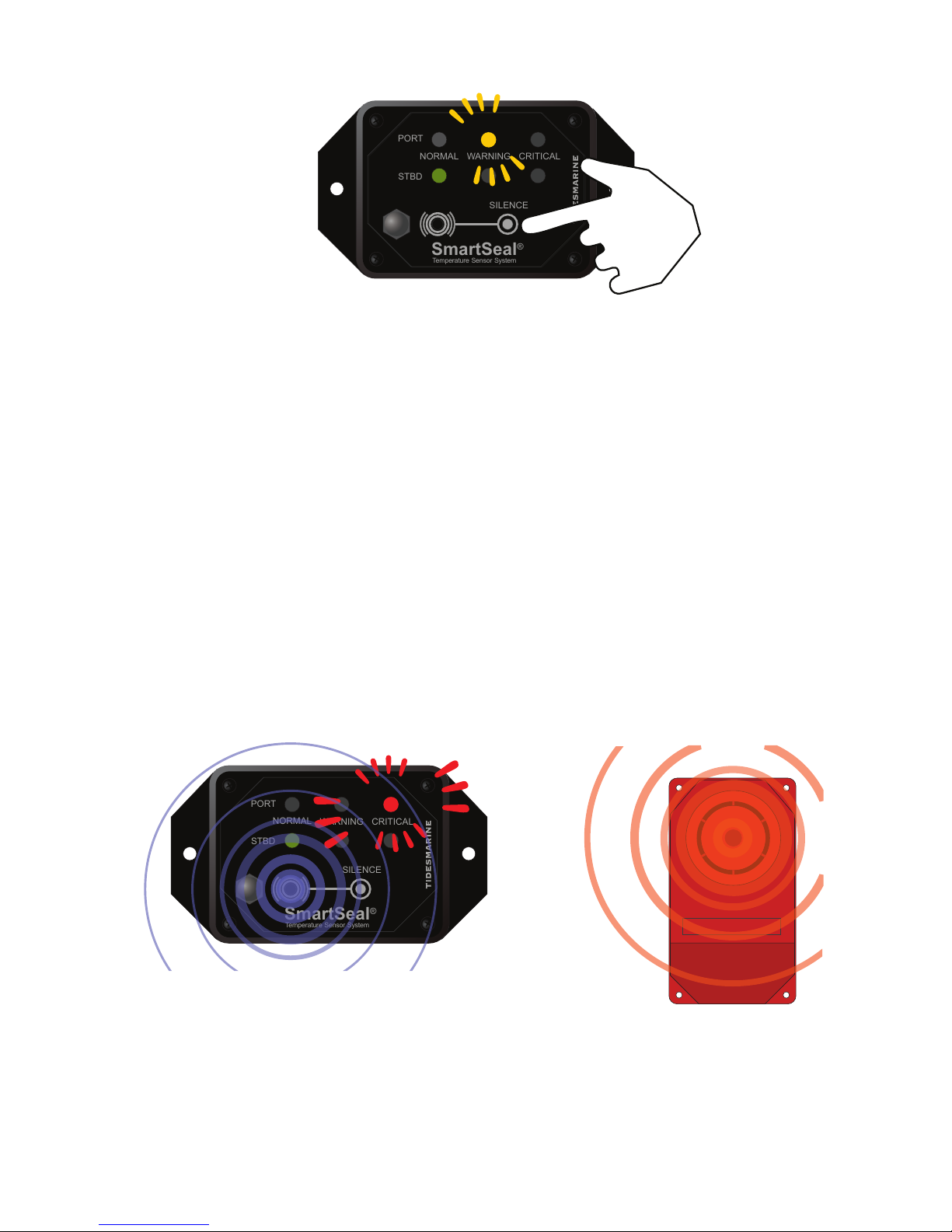
The audible onboard alarm may be silenced by pressing the “SILENCE”
control on the front panel of the Main Control Unit. THIS ACTION DOES
NOT INDICATE THAT THE ISSUE CAUSING THE ELEVATED
TEMPERATURE HAS BEEN FIXED.
If the shaft seal temperature remains above 50° C (122° F) the yellow
LED(s) will continue to flash and the alarm will activate again. After
resolving the issue causing the elevated temperature warning, the
“NORMAL”green status LED(s) will illuminate.
Silence Alarm / Siren
Rapidly Flashing Red LEDs with Alarm & Siren Sound
-indicate CRITICAL ALERT condition
+
PORT
STBD
NORMAL CRITICAL
WARNING
SILENCE
Temperature Sensor System
®
SmartSeal
Critical Alert State
A Critical Alert is indicated by the Red LED(s) flashing rapidly. The
audible alarm and external siren (if equipped) will sound with every flash.
This indicates that the shaft seal temperature is above 70° C (158° F),
and that ACTION MUST BE TAKEN IMMEDIATELY TO RESOLVE THE
PROBLEM.
The Critical alert audible alarm and external siren may be silenced via the
control on the Main Control Unit front panel. Once the problem has been
solved and the shaft seal begins to cool down, the Warning State may
temporarily occur. Once the shaft seal temperature goes below 50° C
(122° F), the green LED(s) will illuminate and audible alarms will stop.
PORT
STBD
NORMAL CRITICAL
WARNING
SILENCE
Temperature Sensor System
®
SmartSeal
System Operation
There are three states of operation: “NORMAL, WARNING and CRITICAL”
which are indicated by the LEDs on the front panels of each unit in
operation. For twin engine configurations the Port and Starboard states are
independent of each other such that one may be normal when the other
indicates an overheating condition.
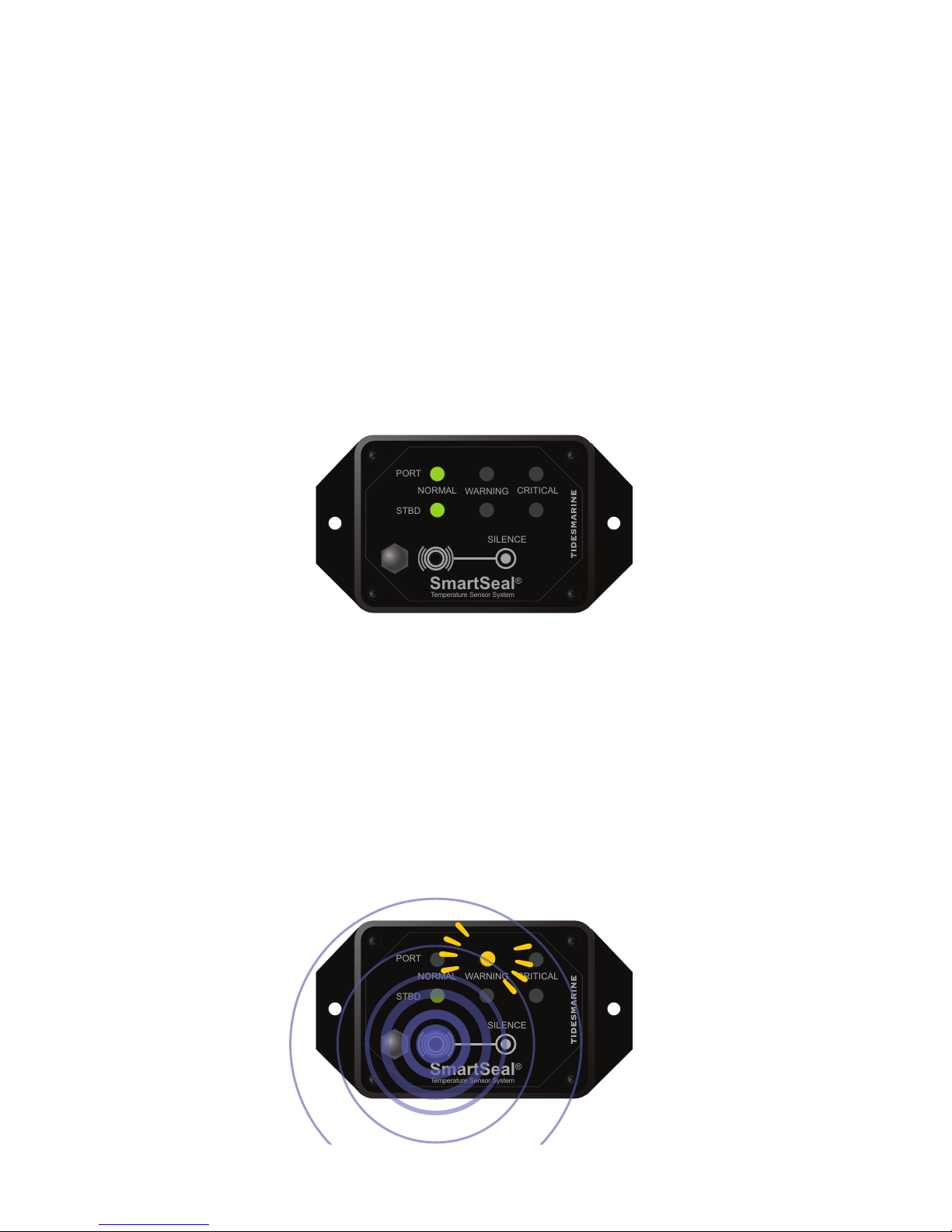
Normal Operation
Normal state is indicated by the Green LED(s) being illuminated when the
engines are running. This indicates that the system is operating with the
shaft seal temperature below 50° C (122° F).
Warning State
Warning State is indicated by the Yellow LED(s) flashing slowly (every 4
to 5 seconds). The audible alarm will sound with every flash. This
indicates that the shaft seal temperature is above 50° C (122° F) but less
than 70° C (158° F).
Steady Green LEDs- indicate Normal Operation
Slowly Flashing Yellow LEDs with Alarm Sound- indicate WARNING condition
PORT
STBD
NORMAL CRITICAL
WARNING
SILENCE
Temperature Sensor System
®
SmartSeal
87
PORT
STBD
NORMAL CRITICAL
WARNING
SILENCE
Temperature Sensor System
®
SmartSeal
The audible onboard alarm may be silenced by pressing the “SILENCE”
control on the front panel of the Main Control Unit. THIS ACTION DOES
NOT INDICATE THAT THE ISSUE CAUSING THE ELEVATED
TEMPERATURE HAS BEEN FIXED.
If the shaft seal temperature remains above 50° C (122° F) the yellow
LED(s) will continue to flash and the alarm will activate again. After
resolving the issue causing the elevated temperature warning, the
“NORMAL”green status LED(s) will illuminate.
Silence Alarm / Siren
Rapidly Flashing Red LEDs with Alarm & Siren Sound
-indicate CRITICAL ALERT condition
+
PORT
STBD
NORMAL CRITICAL
WARNING
SILENCE
Temperature Sensor System
®
SmartSeal
Critical Alert State
A Critical Alert is indicated by the Red LED(s) flashing rapidly. The
audible alarm and external siren (if equipped) will sound with every flash.
This indicates that the shaft seal temperature is above 70° C (158° F),
and that ACTION MUST BE TAKEN IMMEDIATELY TO RESOLVE THE
PROBLEM.
The Critical alert audible alarm and external siren may be silenced via the
control on the Main Control Unit front panel. Once the problem has been
solved and the shaft seal begins to cool down, the Warning State may
temporarily occur. Once the shaft seal temperature goes below 50° C
(122° F), the green LED(s) will illuminate and audible alarms will stop.
PORT
STBD
NORMAL CRITICAL
WARNING
SILENCE
Temperature Sensor System
®
SmartSeal
System Operation
There are three states of operation: “NORMAL, WARNING and CRITICAL”
which are indicated by the LEDs on the front panels of each unit in
operation. For twin engine configurations the Port and Starboard states are
independent of each other such that one may be normal when the other
indicates an overheating condition.
Normal Operation
Normal state is indicated by the Green LED(s) being illuminated when the
engines are running. This indicates that the system is operating with the
shaft seal temperature below 50° C (122° F).
Warning State
Warning State is indicated by the Yellow LED(s) flashing slowly (every 4
to 5 seconds). The audible alarm will sound with every flash. This
indicates that the shaft seal temperature is above 50° C (122° F) but less
than 70° C (158° F).
Steady Green LEDs- indicate Normal Operation
Slowly Flashing Yellow LEDs with Alarm Sound- indicate WARNING condition
PORT
STBD
NORMAL CRITICAL
WARNING
SILENCE
Temperature Sensor System
®
SmartSeal
87

SmartSeal Troubleshooting
Main Control
Unit Has No
LEDs
Illuminated
Main Control
Unit Powers up
and the RED
LEDs are
Blinking and
the Audible
Alarm is
Sounding
All LED Colors
Are Flashing in
Unison
Remote LEDs
or audible
alarm are not
functioning
Ensure that the SmartSeal Temperature Sensor
is properly connected to the NMEA 2000 network
and is getting power.
If this is a vessel without a NMEA 2000 network,
ensure that the power connector is properly
connected to the “private” network and the 12V
power source is operating correctly.
Verify that the harness cable(s) are
properly connected to the Main control
unit.
Inspect the ring thermistor(s) at the
injection fitting(s) for poor connection to
the sensor cable. If any problem is
found, replace the sensor cable.
This condition is due to a failure
detected in the Main control unit self-test
which occurs on each power up. Other
internal issues could cause the self-test
to fail. In this case, please contact
Technical Support for assistance.
This is the same indication as the power up
flashing Red LEDs above but the error has been
detected while the Main control unit is operating
(vs powering up as above).
Verify that the sensor cable(s) are properly
connected to the Main control unit.
Inspect the ring thermistor(s) at the injection
fitting(s) for poor connection to the sensor cable.
If any is found, replace the sensor cable.
Remote units are designed to enter this state if
no communication is received from the Main
control unit. This condition can also occur if the
Remote unit is not receiving power.
Ensure the Remote is properly connected to the
NMEA 2000 network or the “private” network
created on installation and that it is receiving
power.
Ensure the Main unit is powered and operating.
System Operation
Possible Causes of Alerts
In general, the temperature of the shaft seal may become elevated if there is
a problem with the cooling water supply to the shaft seal which is necessary.
If an alert has occurred, check for the following:
-Twisted, kinked or leaking water pick-up line from engine to shaft seal.
-Water pick-up line has become blocked with debris (sand, rust particulate
etc.)
-Crossover water line (twin engine applications) is either kinked or blocked
when only one engine is running.
-Water pump malfunction
System Self Test
The SmartSeal Temperature Sensor system has a built in self-test function.
When the system is powered on, both the Main Control and Remote
Monitoring units will cycle through each LED color 2-3 times indicating all
internal self-tests have passed and the unit is operating correctly. In
addition, the Main Control Unit will beep one or two times indicating it is a
single or twin engine unit. The Remote will beep once in either a single or
twin engine installation.
Error Indications
If the self test determines that the Smart Seal System is not operating
correctly after power up, the following error indications will be displayed
Red LEDs flashing and audible alarm sounding rapidly.
-Occurs if the system is powered up and there is a problem in one or both of
the thermal sensor connections of the Sensor cable.
All three LED colors are flashing.
-Occurs, while the system is operating, if trouble is detected in one of the
thermal sensor connections.
The Remote Unit(s) have no illuminated LEDs
-This indicates that the Remote unit(s) are either or both not receiving data
from the Main Control Unit or power from the network to which it is
connected.
109

3251A S.W. 13th Drive
Deereld Beach, FL 33442
Toll Free Phone: (800 420-0949
General Phone: (954) 420-0949
General Fax: (954) 420-5234
Order Fax: (954) 420-0945
WWW.TIDESMARINE.COM
TIDESMARINE
innovative products for the marine industry
© 2018 Tides Marine All Rights Reserved
User Manual- Smart Seal Rev 1.0
This manual suits for next models
5
Table of contents
Popular Marine Equipment manuals by other brands


Garmin
Garmin FUSION APOLLO MS-WB675 manual

Garmin
Garmin Gladiator TR-1 owner's manual

DESSALATOR
DESSALATOR AC PRO AUTOMATIC COMPACT D90 Assembly and user's manual

Observator Instruments
Observator Instruments OMC-131 Installation and technical manual

Safran
Safran MorphoAccess SIGMA Series Administration guide

Exalto
Exalto 255BSS user manual