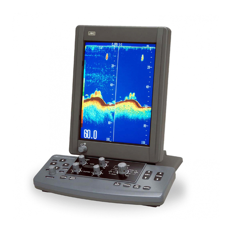
TMQ AP55 Display Head Instruction Manual

AP55 Display Head
OPERATION AND INSTALLATION MANUAL
www.tmq.com.au

TMQ AP55 Display Head Page 2 Ver1.0 0 /12/2005
This Page is Blank

TMQ AP55 Display Head Page 3 Ver1.0 0 /12/2005
Index
W
ARNING
!............................................................................................................. 4
I
NTRODUCTION
...................................................................................................... 5
B
LOCK
D
IAGRAM OF FULL SYSTEM
......................................................................... 6
D
EFINITION OF
T
ERMS
............................................................................................ 7
O
PERATION OF
AP55
D
ISPLAY
H
EAD
......................................................................
T
URNING THE UNIT
ON
/
OFF............................................................................... 10
MANUAL
M
ODE
................................................................................................ 10
Possible alarms................................................................................................10
AUTO
M
ODE
...................................................................................................... 11
GPS
M
ODE
.......................................................................................................... 13
R
UDDER
S
ENSITIVITY
/
R
ATIO
.............................................................................. 16
B
ACKLIGHTING
.................................................................................................... 17
R
UDDER
A
NGLE
I
NDICATOR
................................................................................. 17
I
NITIAL
S
ETTINGS
................................................................................................. 1
R
UDDER
L
IMITS
................................................................................................... 1
R
ESET
R
UDDER
L
IMITS
......................................................................................... 19
C
OMPASS
C
ALIBRATION
....................................................................................... 19
O
FF
C
OURSE
A
LARM
............................................................................................ 22
REMOTE
P
OWER
S
TEER
(R
EMOTE
U
NIT
O
PERATION
).......................................... 23
A
LARMS
.............................................................................................................. 25
I
NSTALLATION OF
AP55
D
ISPLAY
U
NIT
................................................................ 26
A
DDITIONAL
D
ISPLAY
U
NITS
:............................................................................... 26
Figure 1 Connections for AP55 Display Unit ..................................................27
Figure 2 AP55 Display Unit Connections......................................................27
O
PTIONAL
E
XTRAS
............................................................................................... 2
Hydraulic Drives and Pump Units....................................................................30
C
IRCUIT
D
IAGRAM
S........................................................................................ 32-33
AP55 Circuit
AP55 Layout

TMQ AP55 Display Head Page 4 Ver1.0 0 /12/2005
Warning!
Automatic pilots are designed to be a navigational aid. As an automatic
steering aid, an autopilot can alleviate the boredom of hand steering.
This allows the operator of the vessel time to attend to other duties, keep
a more accurate check of navigation duties or just relax and enjoy the
trip.
HOWEVER, THE AUTOPILOT SHOULD NOT BE
LEFT SOLELY IN CHAR E OF THE VESSEL AND AN
ADEQUATE WATCH SHOULD BE MAINTAINED AT
ALL TIMES.
IT IS STRON LY RECOMMENDED THAT THE
AUTOPILOT SHOULD NOT BE USED WHILE
NAVI ATIN IN RESTRICTED WATERWAYS AS
WATER CURRENTS, WIND CHAN ES OR RADIO
TRANSMITTER INTERFERENCE CAN ENDAN ER
YOUR OWN OR OTHER VESSELS.

TMQ AP55 Display Head Page 5 Ver1.0 0 /12/2005
Introduction
Congratulations on your wise choice and purchase of the TMQ AP55
Autopilot Display Head. We are sure that you will enjoy the benefits that
it offers.
The AP55 head utilises an existing Autopilot system and provides full
control of the autopilot, indicating in different modes heading, course to
steer and rudder angle.
Complete AP55 Autopilot System
The minimum AP55 Autopilot system must comprise the following
units: -
Essential Electronics:
• AP55 Display head.
• Autopilot control unit
• Rudder feedback unit.
• Fluxgate compass
• Drive unit, for example
- Hydraulic system with solenoid valves.
- Reversing hydraulic pump system.
- Mechanical motor drive system.

TMQ AP55 Display Head Page 6 Ver1.0 0 /12/2005
Options:
• Compass Top Sensor
• Heavy Duty Rudder Sensor
• Electric steering wheel or lever
• Remote Station Devices including: -
1. Remote panel
2. Hand remote
3. Steering lever
4. Steering wheel
5. Rudder angle indicators (RAI), if desired
See Optional Extras at the rear of this manual for details.
Block Diagra of full syste

TMQ AP55 Display Head Page 7 Ver1.0 0 /12/2005
Definition of Ter s
Heading:
The magnetic heading of the vessel at the current time.
Course-to-steer:
The magnetic heading which the autopilot is attempting to
achieve.
Display Unit:
The unit with LCD digital display and keypad used to send
commands to the C-Drive assembly.
Remote Unit:
This is a collective term for a “panel remote”, “hand remote”,
“steering lever” or “steering wheel” station. Each of these
function in similar ways, but differ in appearance.

TMQ AP55 Display Head Page Ver1.0 0 /12/2005
Operation of AP55 Display Head
Buttons or mode selection on the AP55 unit will select one of the
possible steering modes in the Autopilot unit. It is the Autopilot
assembly, which generates signals to the steering motor (whether
mechanical, hydraulic, or other type).
The following is a brief list of the capabilities of the autopilot. Each is
described in more detail in a separate chapter.
• MANUAL Mode: “H***”
The autopilot Display Unit shows the current magnetic heading.
The vessel is under manual steering control; the autopilot will not
apply any steering control.
• AUTO Mode: “A***”
The autopilot will maintain your vessel on any desired magnetic
course. This course can be set from the Display Unit.
• PS Mode: “A***”
When receiving information from a GPS unit, the autopilot can steer
a vessel to a precise latitude and longitude, or through a sequence of
latitudes and longitudes.
• REMOTE AUTO Mode: “A***”
With a hand remote, panel remote, steering lever or steering wheel
station installed, this will allow steering by compass with the desired
course adjustable from the remote station.

TMQ AP55 Display Head Page 9 Ver1.0 0 /12/2005
• REMOTE POWER STEER Mode: “P***”
With a hand remote, panel remote, steering lever or steering wheel
station installed, this will allow control of rudder position from the
remote station.
• RUDDER and RESPONSE Settings:
These customise the AP55 Autopilot for your vessel’s steering.
They may also be used to adjust for varying sea conditions.
• Compass Calibration:
The AP55 compass can be calibrated on the vessel using a simple
procedure.
• Rudder Angle Displays:
The AP55 Display Unit LCD can be set to display the rudder angle
as a numeric number.
• Selectable backlighting:
When using the autopilot at night, the backlighting can be turned on.

TMQ AP55 Display Head Page 10 Ver1.0 0 /12/2005
Turning the unit ON / OFF
The power to the Autopilot motor control unit should be
via a suitable circuit breaker. Turning this on will provide
power for the Autopilot unit and the AP55 Display Head.
MANUAL Mode
In this mode
• The display screen shows “H***”, *** being the current vessel
magnetic heading in degrees.
• The drive unit clutch is disengaged,
• No steering control is generated.
Possible alarms
• No Autopilot alarm “ nrd ”

TMQ AP55 Display Head Page 11 Ver1.0 0 /12/2005
AUTO Mode
• Press the AUTO button. AUTO mode will be selected. A beep will
sound and the text display will change to “A***”. The Auto LED
will light
The autopilot will lock on the current heading.
The course-to-steer is shown on the display.
Disengaging AUTO mode:
Press the AUTO button, a beep will sound and the vessel will
return to manual steering.
Changing the position of the remote unit switch can select
REMOTE AUTO, REMOTE POWER STEER, or MANUAL
modes.
Course Adjustment:
Each press of the < or > buttons will cause a one degree per
segment course change in the applicable direction. The display
will change to indicate the new course-to-steer. By pressing and
holding the buttons pressed will cause the change to be at 10
degrees per second for larger turns.

TMQ AP55 Display Head Page 12 Ver1.0 0 /12/2005
IMPORTANT!!
Before entering AUTO mode, ensure that the rudder
is in the centre position (i.e.: the vessel is steering
approximately straight ahead). If you do not do this,
the course steered will be different to what is
displayed.
The AP55 Autopilot will select the position of the rudder when
AUTO is selected as the position of the rudder to allow the vessel
to steer straight ahead. This can be an advantage in most vessels
when a slight amount of helm from the physical centre position is
required for the vessel to go straight.

TMQ AP55 Display Head Page 13 Ver1.0 0 /12/2005
GPS Mode
For use when interfaced to a GPS or plotting system generating NMEA
01 3 data output in the correct sentence format. GPS mode allows the
autopilot to be directed by the GPS, enabling automatic heading changes
and eliminating the effects of wind and tide.
The digital display indicates the course-to-steer, which will be the
bearing between the origin and destination waypoints, plus a factor to
correct for the current cross track error (XTE).
Engaging PS Mode:
Press the MODE button and, while the MODE button is pressed,
press the AUTO button.
A beep will sound and the GPS and AUTO LED will be
illuminated.
The autopilot will lock on to course to steer as requested by the
GPS.
The course-to-steer is shown on the display.
The vessel will begin turning from its Heading to that requested
by the GPS unit, at a maximum rate of 10 degrees per second.
If no GPS data is received by the AP55, the autopilot will lock
onto the course of the vessel at the time that GPS Mode was
engaged, and the “NO GPS DATA” alarm will function.

TMQ AP55 Display Head Page 14 Ver1.0 0 /12/2005
Disengaging PS Mode:
Pressing the AUTO button will return the AP55 to Manual Mode.
Setting up your PS unit:
Because there are a great variety of GPS units that will work with
this autopilot, the following is a guide only. For more
information, consult your GPS manual.
The GPS unit must be set up to output “NMEA 01 3” data on a
pair of wires, which are connected to the NMEA socket on the
AP55 C-Drive unit. The data generated must include at least one
of the following:
• The APA sentence.
• The APB sentence.
• The BOD and XTE sentences.
• If only the XTE data sentence is available, the pilot can steer in a
restricted manner only. (See later in this section.)
The GPS unit must be programmed and activated to navigate to a
waypoint, or to follow a line joining two or more waypoints (called a
route). This unit should then send information to the autopilot from
which can be calculated the course-to-steer.
Under the following conditions:
• Several waypoints are linked together into a single route,
• The GPS unit is set and capable of “auto-sequence” between them,
• An “arrival zone” of more than 0.05 NM (Nautical Miles) is set so
that the GPS can detect when the vessel has reached a waypoint.

TMQ AP55 Display Head Page 15 Ver1.0 0 /12/2005
Then the AP55 will be able to steer from each waypoint to the next
without intervention.
If only the XTE information is available from your GPS unit then
your vessel must be on track, and heading in the correct direction,
before engaging the GPS unit. The “auto sequence” feature is not
available in this instance.
Remember:
Prior to engaging GPS mode, a route or destination must be programmed
and selected in the GPS for the Autopilot to follow.
No PS Data Alarm:
If the autopilot is not receiving valid information while in GPS
Mode, the alarm will sound, and GPS and AUTO LED will flash.
This could be caused by:
• Incorrect wiring of the GPS to the C-Drive unit.
• Incorrect data output (wrong sentence) from the GPS unit.
• No route set up or selected in the GPS unit
• No location fix at the GPS unit.
The course over ground information generated by the GPS unit
should closely correspond to the magnetic heading signal the AP55
is receiving from its magnetic compass. The greater the difference
between these headings, the less accurate will be the GPS Mode
steering.
• Ensure that the GPS unit has the correct magnetic correction factor.
• Ensure that theAP55 compass is correctly aligned and installed, and
not subject to magnetic interference.

TMQ AP55 Display Head Page 16 Ver1.0 0 /12/2005
Rudder Sensitivity / Ratio
These settings are used to determine how sensitive the autopilot system
is and the amount of rudder the vessel requires for steering (actually, the
amount of rudder angle applied for a given angle off-course).
To adjust, press the MODE button. The display will show “S **” and
the present sensitivity setting will be displayed (between 1 and 10).
• The sensitivity setting may be altered by the < - > Buttons. A
low response value the drive will operate with minimum
pulsing to the required rudder position and the autopilot
system may work continuously.
• A high response value the drive will position the rudder with
maximum pulsing. The vessel’s course will wander slightly.
NOTE: Too low a setting may cause the steering motor to
work continuously (hunting). The response setting should be
increased from 1 until the rudder position is achieved with 1 or 2
motor pulses.
By pressing the MODE button a second time, the display will indicate
“r **”. This setting is used for adjusting the autopilot’s rudder ratio
setting to allow for varying vessel size and speed.
The display shall change to show “r **” and display shall show the
current Rudder ratio (between 1 and 10).
The rudder setting may be altered by the < - > buttons.

TMQ AP55 Display Head Page 17 Ver1.0 0 /12/2005
• A value of 1 signifies the minimum amount of applied
rudder. When the rudder setting is too low, vessel track will
be a slow “ S ” ie: understeer through too little rudder
applied.
• A value of 10 signifies the maximum amount of applied
rudder. When the rudder setting is too high, vessel track will
be a rapid “ S ” ie: oversteer through too much rudder
applied.
Backlighting
Pressing the MODE button four times will display the message “LitE”
Pressing the < > buttons together will toggle the backlighting on and off.
The backlighting will always be off when the unit is powered up.
Rudder Angle Indicator
Pressing the MODE button three times will display the rudder position in
numeric value Port or Starboard
• When the rudder is at centre it will display “ 00”
• As port rudder angle is applied, the number will be “Pt**”.
• As starboard rudder angle is applied, the numbers will be “St**”.
Pressing MODE or AUTO will cancel the rudder display.

TMQ AP55 Display Head Page 1 Ver1.0 0 /12/2005
Initial Settings
Selecting the Initial settings of the Autopilot:
A number of system settings may need to be carried out prior to using
the AP55 Autopilot. Two initial settings can be carried out from the
Display Head.
• Rudder Limits.
• Compass Calibration.
Rudder Li its
The rudder limits prevent the steering motor driving the rudder beyond
its physical (mechanical) stops. The limits are factory set and should not
need altering. However, the limit setting can be set from the display of
the AP55 if deemed necessary.
• Set the rudder to the desired Port position
• Select SET PORT LIMIT. By pressing the MODE button five times
until “PL**” is displayed.
• Press the < > buttons simultaneously to set the Port Limit.
• Set the rudder to the desired Starboard position.
• Select SET STARBOARD LIMIT. By pressing the MODE button
six times until “SL**” is displayed.
• Press the < > buttons simultaneously to set the Starboard Limit.

TMQ AP55 Display Head Page 19 Ver1.0 0 /12/2005
The number on the display will be between 0 and 31 to indicate the
rudder position. “SL31” being fully to Starboard and “PL31” being fully
to port.
If “ oor” (Out of range) is displayed it indicates the rudder is not in the
correct position to set the rudder limit. I.e. Rudder is to port when
setting the Starboard limit.
If at any time during testing the motor runs under load and the rudder
does not move, checks should be carried out to confirm the limit
switches are operating prior to the rudder running into the stops.
Reset Rudder Li its
It is possible to reset the rudder limits to the factory settings if unsure of
the settings.
Press the MODE Button 7 Times
“ rLr” will Display (Reset Limit Rudder).
Press < > both simultaneously to reset rudder limit.
Co pass Calibration
The AP55 Display Head will enable you to complete a compass
calibration. If you have a steel vessel, or some other factor, which causes
the compass to perform poorly, the calibration procedure will adjust
compass characteristics to compensate.

TMQ AP55 Display Head Page 20 Ver1.0 0 /12/2005
NOTE: The calibration should only be done if the compass is
known to be inaccurate when compared to a chart
bearing.
If the AP55 Display Head shows a compass heading with a constant
offset when compared to a correctly calibrated ships compass (eg: the
autopilot compass reads 3 degrees high on all headings), simply rotate
the Autopilot compass sensor to align the displayed headings with the
ships compass. It is not necessary to re-calibrate the compass as
described below.
If the Autopilot has inconsistent variation on different headings, the
following calibration procedure can be carried out. This procedure
should only be done in calm waters with adequate sea room. Auto
must not be selected to carry out the calibration.
1. Using the AP55 Display Head, Press the MODE button times to
enter the compass calibrate mode “CCAL”
2. Press the < > buttons simultaneously to start the compass
calibrate. The Display will change to “StrC”
3. Start turning the vessel slowly in one direction. Turn vessel
slowly through two complete circles from this point. Each
complete turn should take at least 60 seconds.
4. On completion of circles, press the < > buttons together to store
the calibration setting into memory.
Check alignment of the Autopilot compass by steering the vessel due
North (000 on ships compass) and, if necessary, rotate the compass
sensor until display reads 000.
Other manuals for AP55 Display Head
1
Table of contents
Other TMQ Marine Equipment manuals
