TIE DOWN TranzSporter 48469 User manual
404-344-0000 • tiedown.com
605 Stonehill Drive SW, Atlanta, GA 30336
Red: 0-100-100-0 Blue: PMS 293
100-56-0-0
Color Logo use on white background only
Black Logo use on white background only
White Logo use on black background only
E1414; Rev. 1/3/19
Instructions #08243
Updated: 1/3/19
For the Most Up to Date
Information and Instructions, Visit the TranzSporter Web Site at
www.tranzsporter.com.
Solar/ Plywood
Panel Accessory
Owners Manual
Solar/Plywood Panel Accessory for TP250 Platform Hoist
Part #48469
Kit Includes: solar brackets left and right, roof top anchor kit, cable drum assembly with extended cable,
solar/plywood carriage weldment.
Solar/Plywood Panel Accessory for TP400 Platform Hoist
Part #48467
Kit includes: solar brackets left and right, roof top anchor kit.
Both TP250/400 Models
Requires Secondary Handle Kit #48468
Tie Down • Atlanta, Georgia 30336
1
Safety Instructions
CAUTION: Please read the safety warnings and instructions contained in this manual before operating the lift hoist. Failure
to obey the warnings contained herein could result in damage to the equipment, personal injury, or death, this information
should not be a substitute for routine accident prevention, but rather an addition to routine accident prevention.
GENERAL SAFETY INSTRUCTIONS:
1. Transport and handle your lift hoist with care.
2. Unpack the TranzSporter carefully and inspect for any damage that may occur during transportation. DO NOT USE THE HOIST IF ANY
PART IS DAMAGED.
3. Please observe all safety and warning labels attached to the hoist.
4. Use only replacement parts furnished by the manufacturer.
5. Always keep the area around the base section of the TranzSporter hoist clear to help prevent slipping, tripping or falling against the hoist.
6. DO NOT ALLOW ANYONE TO OPERATE THE TRANZSPORTER HOIST WHO HAS NOT BEEN THOROUGHLY AND PROPERLY
TRAINED IN THE CORRECT OPERATION AND USE OF THIS HOIST.
7. This hoist is manufactured to lift materials only. Do not use the lift hoist for the purpose of transporting personnel from one level to another.
8. Do not climb the TP-Series hoist or use as a personnel ladder.
9. Do not overload - maximum lifting capacity for the TP250 is 250 lbs. with a load capacity of 230 lbs.
Maximum lifting capacity for the TP400 is 400 lbs. with a load capacity of 380 lbs.
10. Keep hands, feet and other body parts as well as clothing away from the track sections and moving or rotating parts of the TP-Series hoist
when starting the engine or when operating the hoist.
11. Do not allow any persons to walk or work under or near the TP-Series hoist while in operation.
12. Do not use this hoist to transport hot asphalt or any other hot molten substance from one elevation to another.
13. Store all parts of the TP-Series hoist in such a fashion as not to damage any of the components.
14. Do not operate indoors or in an area with poor ventilation. Electric motor model is excluded.
15. Never lift sheet or panel goods without the use of the plywood brackets and the tie down straps provided (see page 9).
Warning labels are attached to the TP250/400 and are weather resistant. If you notice any of these decal’s missing from your
hoist, please contact TIE DOWN ENGINEERING for a replacement label.
Remember: Safety First!!
15640-2
WARNING
DO NOT REMOVE THIS TAG!
SHOCK HAZARD
KEEP ENTIRE LIFT HOIST
CLEAR OF ALL UTILITY
AND ELECTRICAL WIRING!
15641-2
DO NOT REMOVE THIS TAG!
IMPORTANT SAFETY INFORMATION
• TOP OF HOIST MUST BE SECURED TO ROOF USING “S” HOOKS (PROVIDED)
AND TWO LENGTHS OF ROPE (NOT PROVIDED)
• BRAKE TENSION SPRINGS MUST BE CHECKED FOR CORRECT TENSIONING DAILY
(BEFORE USE) IN ORDER TO PREVENT LOAD SLIPPAGE
• KEEP BRAKE DRUMS AND BRAKE SHOES FREE OF OIL, LUBRICANTS, AND
EXCESSIVE MOISTURE, CHECK FOR DAILY WEAR AND REPLACE WHEN NECESSARY
• DO NOT OPERATE THIS UNIT IF ANY COMPONENT PARTS EXHIBIT DAMAGE
OR WEAR. THIS INCLUDES ALL TRACK SECTIONS
WARNING
SAFETY LATCH MUST BE
ENGAGED WHEN LIFT
HOIST IS NOT IN USE
DO NOT REMOVE THIS TAG!
15642-2
Instructions Inside Tube
(Remove Red End Cap to Read)
WARNING WARNING WARNING
FAILURE TO READ AND UNDERSTAND THE OPERATING
INSTRUCTIONS CAN RESULT IN PROPERTY DAMAGE,
PERSONAL INJURY OR EVEN DEATH TO USER OR OTHERS
#15726
15640-2
WARNING
DO NOT REMOVE THIS TAG!
SHOCK HAZARD
KEEP ENTIRE LIFT HOIST
CLEAR OF ALL UTILITY
AND ELECTRICAL WIRING!
15641-2
DO NOT REMOVE THIS TAG!
IMPORTANT SAFETY INFORMATION
• TOP OF HOIST MUST BE SECURED TO ROOF USING “S” HOOKS (PROVIDED)
AND TWO LENGTHS OF ROPE (NOT PROVIDED)
• BRAKE TENSION SPRINGS MUST BE CHECKED FOR CORRECT TENSIONING DAILY
(BEFORE USE) IN ORDER TO PREVENT LOAD SLIPPAGE
• KEEP BRAKE DRUMS AND BRAKE SHOES FREE OF OIL, LUBRICANTS, AND
EXCESSIVE MOISTURE, CHECK FOR DAILY WEAR AND REPLACE WHEN NECESSARY
• DO NOT OPERATE THIS UNIT IF ANY COMPONENT PARTS EXHIBIT DAMAGE
OR WEAR. THIS INCLUDES ALL TRACK SECTIONS
WARNING
SAFETY LATCH MUST BE
ENGAGED WHEN LIFT
HOIST IS NOT IN USE
DO NOT REMOVE THIS TAG!
15642-2
(404) 344-0000 • www.tranzsporter.com 2
Cable Drum Replacement for the TP250 Hoist
(Instructions for the TP400 Hoist skip to page 6.)
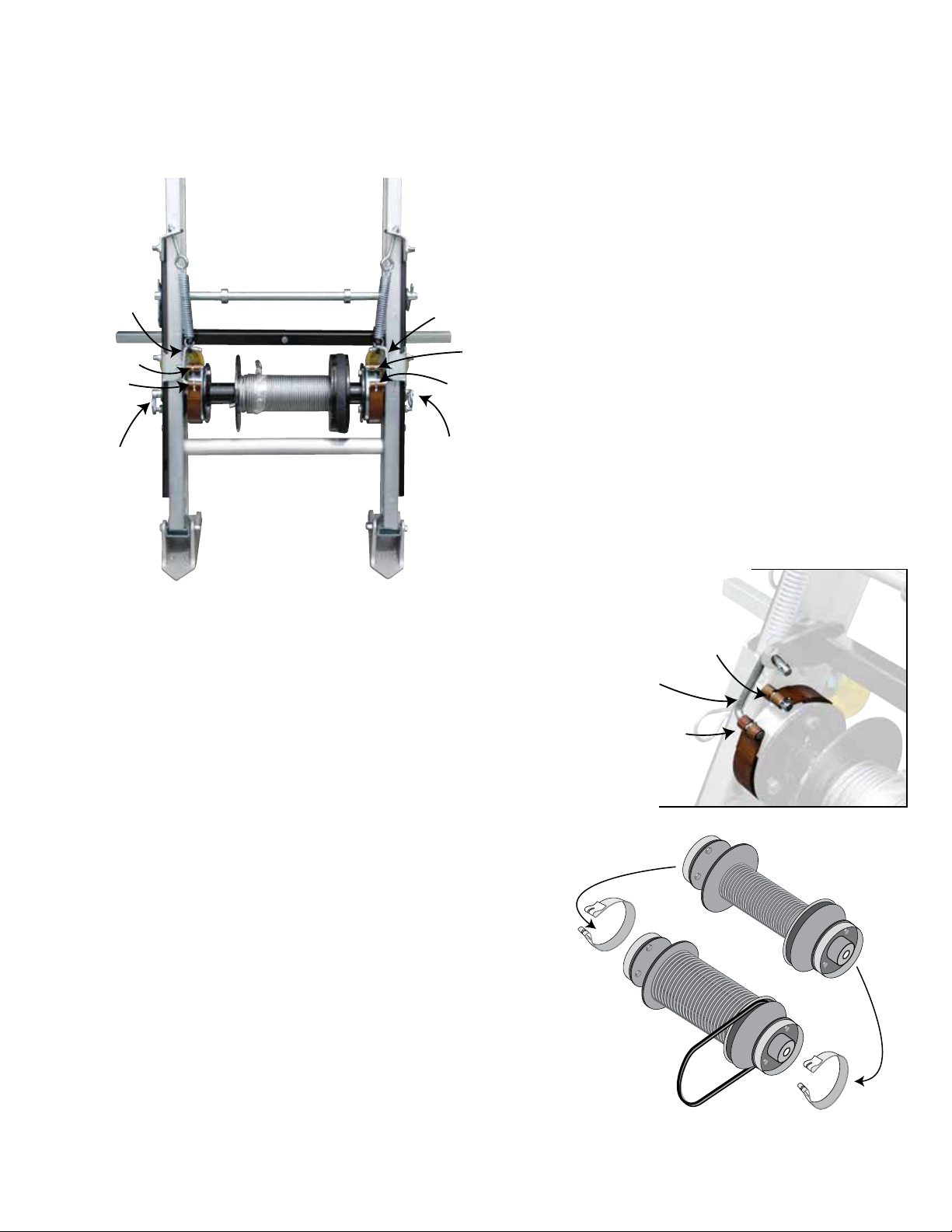
Lowest Brake
Strap/Cotter Pin
Lowest Brake
Strap/Cotter Pin
Lowest Brake
Strap/Cotter Pin
Lowest Brake
Strap/Cotter Pin
Brake
Linkage
Brake
Linkage
Brake
Linkage
Brake
Linkage
Upper Brake Strap
with Brake Post
Upper Brake Strap
with Brake Post
Upper Brake Strap
with Brake Post
Upper Brake Strap
with Brake Post
Brake Control
Shaft/Safety Pin
Brake Control
Shaft/Safety Pin
Lowest Brake
Strap/Cotter Pin
Lowest Brake
Strap/Cotter Pin
Lowest Brake
Strap/Cotter Pin
Lowest Brake
Strap/Cotter Pin
Brake
Linkage
Brake
Linkage
Brake
Linkage
Brake
Linkage
Upper Brake Strap
with Brake Post
Upper Brake Strap
with Brake Post
Upper Brake Strap
with Brake Post
Upper Brake Strap
with Brake Post
Brake Control
Shaft/Safety Pin
Brake Control
Shaft/Safety Pin
In order for the Solar/Plywood carriage to function properly the cable drum must be replaced with higher
capacity and longer length cable.
Step #1
Lay the base section flat on the ground with back
side up. Place the handle on either side of the brake
release bar. Pull the brake handle down towards the
hoist feet, this will release tension on the drum and
may require two people.
Step #2
While tension is applied to the brake release,
remove small cotter pin on lowest brake strap. Slide
the brake linkage out of the drum brake strap.
Repeat for the other side. Release the brake handle.
Step #3
Remove the small cotter pin from the upper drum brake strap. Slide the
brake strap over the brake drum releasing it from the brake post. Repeat
for the other side.
Step #4
Remove the safety pin/washer from one side of the
brake control shaft. Pull out the brake control
shaft from the opposite side of the base.
Step #5
Using both hands: grab the cable drum assembly and the brake straps.
Pull straight outward until the assembly is fully free of the base section.
Set the cable drum assembly to the side.
Step #6
Place the replacement cable drum in front of the TP250 cable drum as-
sembly (side by side, only front and back). Make sure the “V” belt drive
is in the same side/position for both assemblies. Move drive belt to the
replacement cable drum. Slide off the brake straps on both ends and
place them in the same position on the replacement cable drum.
See illustration on right.
TP250 Cable Drum
Solar/Plywood
Cable Drum
3
Cable Drum Replacement for the TP250 Hoist
Continued
Lowest Brake
Strap/Cotter Pin
Lowest Brake
Strap/Cotter Pin
Lowest Brake
Strap/Cotter Pin
Lowest Brake
Strap/Cotter Pin
Brake
Linkage
Brake
Linkage
Brake
Linkage
Brake
Linkage
Upper Brake Strap
with Brake Post
Upper Brake Strap
with Brake Post
Upper Brake Strap
with Brake Post
Upper Brake Strap
with Brake Post
Brake Control
Shaft/Safety Pin
Brake Control
Shaft/Safety Pin
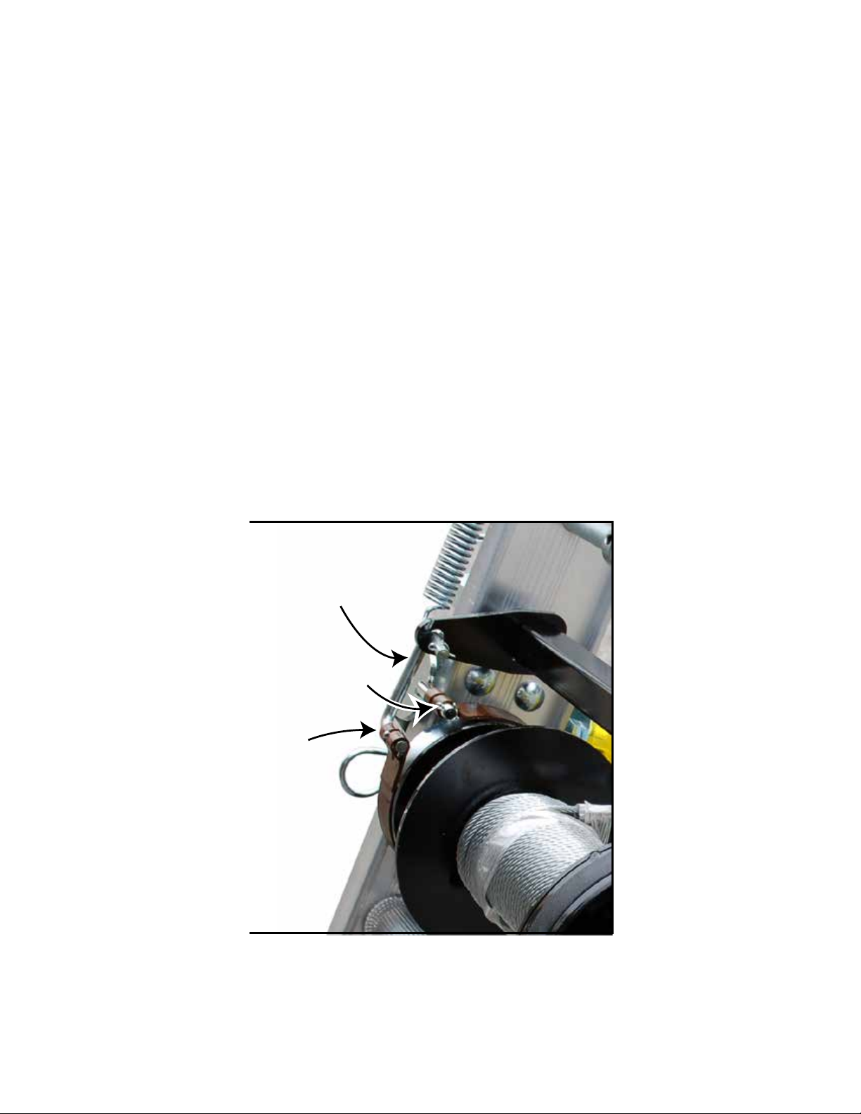
Step #9
Slide the upper brake strap over the brake post. Attach small cotter pin to the end of the brake post. Repeat for the other side.
Step #10
Pull the brake handle down towards the hoist feet, this will release tension on the drum and may require two people. While tension is applied
to the brake release, slide the brake linkage into the lower drum brake strap. Attach with a small cotter pin. Repeat for the other side. Release
the brake handle.
Step #7
Using both hands: grab the replacement drum assembly and the brake straps. Position the replacement cable drum in front of the base sec-
tion. Slide the assembly straight inward; the cable drum should fit between a “Forked Spacer” on each side.
Step #8
One one side, slide the brake control shaft thru the base section and pass thru the cable drum assembly out the other side on the base section.
Place washer over the control shaft and attach safety pin. The cable drum should rotate freely. Both brake straps should fit over the replace-
ment drums with the “Open” section of the straps on the same side as the tension springs.
Tie Down • Atlanta, Georgia 30336
4
Carriage Replacement for the TP250 Hoist
(Instructions for the TP400 Hoist skip to page 6.)
In order for the Solar/Plywood carriage to function properly the TP250 Carriage must be replaced with the
Solar/Plywood Carriage.
Adjustable Tension
Bracket
Adjustable Tension
Bracket
Double back/feed end
cable through pully on
the back of carriage
(cross bar)
Feed end cabl
e
through pully
Unwind cable
from the back
Attach cable to
the back side of the
pully bracket
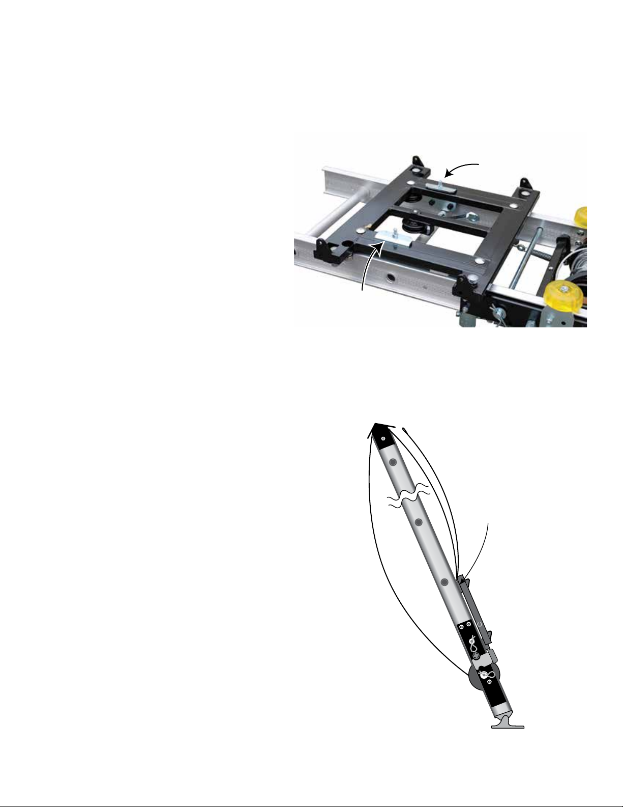
Step #1
Remove the top cap with a 7/16” wrench.
(one bolt/nut on each side)
Step #2
Starting at the top of the track section position the carriage
so that it matches the photo on the right. Slide carriage
assembly onto track section so that the four rollers connect
to the top rail of the track section.
Step #3
Adjust Tension Bracket - Make sure the Solar/Plywood
carriage rollers are on track, and the carriage rolls easily.
There are two adjustable track roller guides on the inside
carriage assembly (see right). Turn the nut clockwise or
counter clockwise to adjust the tension (free play) between
the carriage and the tracks. If the carriage moves too much
in and out, tighten the adjustable tension bracket nut. Cor-
rect adjustment should allow for minimal contact between
the carriage and the tracks.
Step #4
At this time assemble track sections to the height needed.
Please follow the track assembly instructions included with
your hoist owners manual.
Step #5
From the back side of the hoist, remove the end of the
cable from the drum (shown right). It helps to attach the
brake handle, pulling the brake handle releases the brake
drum. The cable will then easily un-spool. Staying on the
outside (back) of the base section and track section, take
the cable to the top of the last track section.
(404) 344-0000 • www.tranzsporter.com
This manual suits for next models
2
Table of contents
Popular Inverter manuals by other brands


BARRON
BARRON EXITRONIX Tucson Micro Series installation instructions

Baumer
Baumer HUBNER TDP 0,2 Series Mounting and operating instructions

electroil
electroil ITTPD11W-RS-BC Operation and Maintenance Handbook

Silicon Solar
Silicon Solar TPS555-1230 instruction manual

Mission Critical
Mission Critical Xantrex Freedom SW-RVC owner's guide

HP
HP 3312A Operating and service manual


