Tier1 165 Series User manual

Owners Manual
Water Softener
165 Series

2
Table of Contents
3
4
5
7
8
9
12
READ THIS MANUAL FIRST
HOW YOUR WATER CONDITIONER WORKS
UNPACKING / INSPECTION OF TWIN TANK MODEL
INSPECTING AND HANDLING
OPERATING CONDITIONS
STARTUP INSTRUCTIONS
MASTER PROGRAMMING
READ THIS MANUAL FIRST
s Read this manual thoroughly to become familiar with the device and its capabilities before installing or operating your Water Softener. Failure to follow instructions in this
manual could result in personal injury or property damage. This manual will also help you to get the most out of your Softener.
s This system and its installation must comply with state and local regulations. Check with your local public works department for plumbing and sanitation codes. In the
event the codes conflict with any content in this manual the local codes should be followed. For installations in Massachusetts, Massachusetts Plumbing Code 248 CMR
shall be adhered to. Consult your licensed plumber for installation of this system.
s Do not use this water Softener on hot water supplies.
s Do not install this unit where it may be exposed to wet weather, direct sunlight, or temperatures outside of the range specified above.
s Avoid pinched o-rings during installation by applying.
s Softeners are commonly exposed to high levels of iron, manganese, sulfur, and sediments. Damage to pistons, seals, and or spacers within the control valve are not
covered in this warranty due to the harsh environment.
s It is recommended to regularly inspect and service the control valve on an annual basis.
s Do not use water that is microbiologically unsafe without adequate disinfection before or after this system.
s This publication is based on information available when approved for printing. Continuing design refinement could cause changes that may not be included in this
publication. Tier1™ reserves the right to change the specifications referred to in this literature at any time, without prior notice.
Safety Messages
Watch for the following safety messages in this manual:
NOTE: used to emphasize installation, operation or maintenance information which is important but does not
present a hazard.
Example: NOTE: Check and comply with you state and local codes. You must follow these guidelines.
CAUTION: used when failure to follow directions could result in damage to equipment or property.
Example:
CAUTION! Disassembly while under pressure can result in flooding.
WARNING: used to indicate a hazard which could cause injury or death if ignored.
Example:
WARNING! ELECTRICAL SHOCK HAZARD! UNPLUG THE UNIT BEFORE REMOVING THE COVER OR ACCESSING
ANY INTERNAL CONTROL PARTS
3
NOTE: Do not remove or destroy the serial number. It must be referenced on
request for warranty repair or replacement

44
HOW YOUR WATER CONDITIONER WORKS
Why Water Gets Hard And How It Is Softened
All of the fresh water in the world originally falls as rain, snow, or sleet. Surface water is drawn upward by the sun, forming clouds. Then, nearly pure and soft as it starts to fall,
it begins to collect impurities as it passes through smog and dust-laden atmosphere. And as it seeps through soil and rocks it gathers hardness, rust, acid, unpleasant tastes and
odors.
Water hardness is caused primarily by limestone dissolved from the earth by rainwater. Because of this, in earlier times people who wanted soft water collected rainwater from
roofs in rain barrels and cisterns before it picked up hardness from the earth.
Some localities have corrosive water. A softener cannot correct this problem and so its printed warranty disclaims liability for corrosion of plumbing lines, fixtures or appliances.
Iron is a common water problem. The chemical/physical nature of iron found in natural water supplies is exhibited in four general types:
1. Dissolved Iron—Also called ferrous or“clear water”iron. This type of iron can be removed from the water by the same ion exchange principle that removes the
hardness elements, calcium and magnesium. Dissolved iron is soluble in water and is detected by taking a sample of the water to be treated in a clear glass.The
water in the glass is initially clear, but on standing exposed to the air, it may gradually turn cloudy or colored as it oxidizes.
2. Particulate Iron—Also called ferric or colloidal iron. This type of iron is an undissolved particle of iron. A softener will remove larger particles, but they may not be
washed out in regeneration effectively and will eventually foul the ion exchange resin. A filtering treatment will be required to remove this type of iron.
3. Organic Bound Iron—This type of iron is strongly attached to an organic compound in the water. The ion exchange process alone cannot break this attachment
and the softener will not remove this type of iron.
4. Bacterial Iron—This type of iron is protected inside a bacteria cell. Like the organic bound iron, it is not removed bya water softener.
When using a softener to remove both hardness and dissolved iron it is important that it regenerates more frequently than ordinarily would be calculated for hardness removal
alone. Although many factors and formulas have been used to determine this frequency, it is recommended that the softener be regenerated when it has reached 50–75% of the
calculated hardness alone capacity. This will minimize the potential for bed fouling.
If you are operating a water softener on clear water iron, regular resin bed cleaning is needed to keep the bed from coating with iron. Even when operating a softener on water
with less than the maximum of dissolved iron, regular cleanings should be performed. Clean every six months or more often if iron appears in your conditioned water supply. Use
resin bed cleaning compounds carefully following the directions on the container.
CAUTION! Do not use where the water is microbiologically unsafe or with water of unknown quality
without adequate disinfection before or after the unit.
5
Be sure to check the entire unit for any shipping damage or parts loss. Also note damage to the shipping cartons. Contact the transportation company for all damage and loss
claims. The manufacturer is not responsible for damages in transit.
Small parts, needed to install the Softener, are in a parts box. To avoid loss of the small parts, keep them in the parts bag until you are ready to use them.
What is included in the box?
For Model 15, you will expect the following:
1. Control Valve
2. Tank
3. Parts Box
4. Owners Manual
5. Brine Tank Assembly
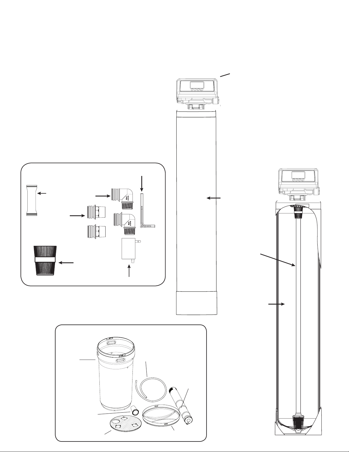
UNPACKING / INSPECTION OF TWIN TANK MODEL
1. Control Valve
2. Tank
Distributor
Tube Inside
the Tank
Media Inside
the Tank.
Media Type
will depend
on what
models were
purchased
Brine Tank
(Round or
Square)
Brine Tank
Tubing
Brine Well/
Safety Float
Brine Tank Lid
Grid (Round or Square)
Grid Legs (3 for
Round and 4 for
Square)
5.Brine Tank Assembly (Round Brine Tank Shown))
3. Parts Box
2X 1”
Straight
Adapter
Bypass Tool
2 X 3/4”
Elbow
Adapter
Transformer
Grease
Packet
Upper Basket

14 6
3. Attaching Bypass to Valve (If required in case of replacing the control valve. The new
control valve comes with bypass attached)
Make sure the bypass is attached well to the control valve. Connect the straight or elbow connectors to the bypass with red clips. Connect the inlet and
outlet of the water Softener to the plumbing of the house. The control valve must not be submitted to temperatures above 43°C
(110°F). When sweat fittings are used, to avoid damaging the control valve, solder the threaded copper adapters to the copper pipe and then, using
Teflon tape, screw the assembly into the bypass valve.
Do not use pipe thread compound as it may attack the material in the valve body.
5. Assembling Brine Tank
a) Attach the three brine grid legs to grid plate.The
legs will snap on to the tabs of the salt plate making
a“click”sound. For square brine tank there are four
legs.)
c) Drop the brine grid with brine well inside the
brine tank such that the nut tting faces the
hole on the brine tank. Then press the grid
evenly inside the brine tank until the brine grid
legs touches the bottom of the brine tank.
b) Insert the brine well assembly inside the grid
plate as well below.
d) Take the brine tube and insert the nut and plastic sleeve as
shown below.
e) Insert the tube in the oat assembly elbow and hand tighten
the nut. In many cases the brine line already come installed
from the factory. Leave the other end of the brine line tube
inside the brine tank
f)For installation of brine tank at the installation site, pull the
other end of the brine tube from the hole on the brine tank.
The completed assembly is shown below.
The hole in
the brine tank
should line up
with the brine
line as shown
for round and
square brine
tank.
IMPORTANT:
IN ROUND
BRINE TANK, IT
IS IMPORTANT
TO ALIGN THE
HANDLE TO
THE BRINE
WELL AS
SHOWN
Insert Sleeve
4Add Salt to the brine tank/cabinet

Optional
Overow
Assembly
Brine Valve
Connector Detail
A
C120V/10A
C
urrent Protect Socket
Brine Elbow
Assembly
Water Pipe Outlet
Main tank
5/8” Drain Line
Bypass assembly
5/8” Overow Line
Floor drain
Optional
Pipes Fixed
Drain Elbow
Assembly
Outlet
Brine Tank
3/8” Brine Tube
Inlet
Water Pipe Inlet
7
Downflow Water Softener Installation
Outlet
Inlet
Cold (Raw water)
Cold (Filtered water) Cold (Raw water)
Water Heater
Hot (Soft Water)
Downow Water Softener
Filter
InIn Out
Out
Cold (Soft Water)
T
o Outside Faucet
In
Out
6. Connect Softener to the House Plumbing Any solder joints near the valve must be done before connecting any piping to the valve. Always leave at least 6”(152 mm)
between the valve and joints when soldering pipes that are connected to the valve. Failure to do this could cause damage to the valve.
Never insert drain line directly into a drain, sewer line, or trap. Always allow an air gap between
the drain line and the wastewater to prevent the possibility of sewage being back-siphoned into
the conditioner.
Structure
Waste connections or drain outlet shall be designed and constructed to provide for connection to
the sanitary waste system through an air-gap of 2 pipe diameters or 1 inch (22 mm) whichever is
larger.
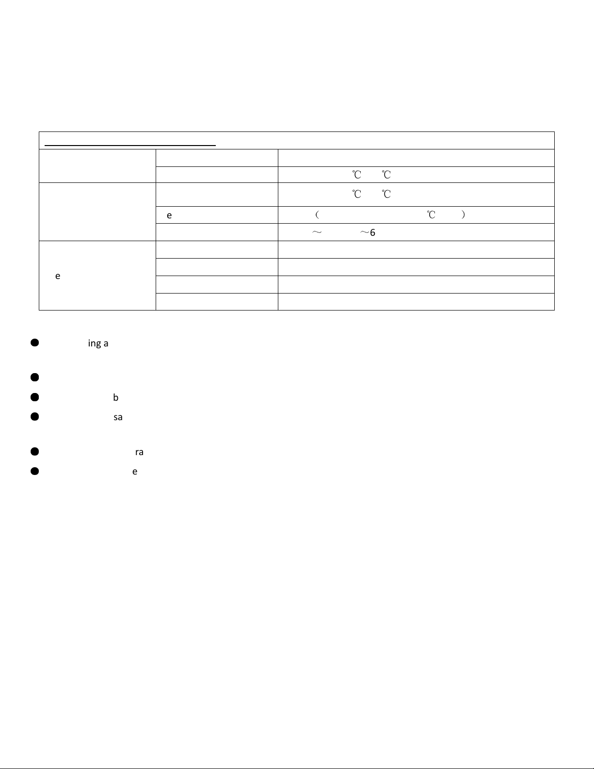
This softening system ill operate at maximum efficiency hen the follo ing conditions are considered.
Operating Conditions:
Working Conditions Working pressure 21psi to 120psi
Water temperature 40 °F - 120 °F (5
℃
- 50
℃
)
Working Environment
Environment
temperature 40 °F - 120 °F (5
℃
- 50
℃
)
Relative humidity ≤ 95%
(
When temperature is 25
℃
/77°F
)
Po er source AC100
~
240V/50
~
60Hz
Inlet Water Quality
Water turbidity Do n-flo Regeneration < 5FTU
Water hardness 1 grain per gallon (gpg) = 17.1 parts per million (ppm)
Chlorine < 0.1ppm
Iron2+ < 0.3ppm
●
●
●
All plumbing and electrical ork should be performed by an accredited professional to ensure all local, state,
and municipal guidelines are met.
●
Do not use the control valve ith ater that is unsafe or of unkno n quality.
●
Do not use the brine tube, injector body, or other connectors on the valve as a handle to carry the system.
●
Ensure there is salt in the brine tank at all times hen this valve is used for softening. The brine tank should contain clean
ater softening salt only, at least 99.5% pure. Do not use small grain salt.
●
When there is moderate to high turbidity, a filter should be installed before the ater softening system on the inlet side.
●
If the ater pressure exceeds 80psi, a pressure reducing valve must be installed before the ater inlet. If the ater
pressure exceeds 80 psi, installing a pressure reducing valve before the ater inlet is highly recommended. If the ater
pressure is under 21psi, a booster pump must be installed before the ater inlet.
Operating Conditions
8

●
•System Start-up
Before operating for the first time, flush out the ater line and bypass. Be sure the bypass is closed.
•Turn the ater source on at the inlet to the house.
•Disconnect the bypass from the valve if attached to the valve.
•Be sure to remove the meter impeller from the bypass before opening the bypass.
•Put a container under the bypass and open the bypass to allo ater to flo through and remove any foreign material
out of the ater lines.
•Close the bypass.
•Reinstall the meter impeller in the outlet side ith the impeller facing in and re-connect the bypass to the valve.
•Open the bypass.
•Check for any leaks.
•Insert meter cable in the outlet side of the bypass or connector, the side the impeller is installed in.
•Plug in the po er cord for the valve.
•Open a ater line and let ater flo until ater runs clear.
•Press and hold both and buttons simultaneously for 3 seconds to unlock the key pad.
•Press to advance to 2 - Back ash; this lets air out of the drain line. Process ill take 8-10 minutes to purge the system.
Note: when you press the screen will display “-00-” as it positions the ceramic discs. Once “-00-” disappears and the
next phase is displayed, you can press to advance to the next phase.
•Press to manually advance through the next phase, 3 - Brine & Slo Rinse. Verify the air check valve is closed by
listening to be sure no air is being dra n into the system. Press to manually advance to the next phase, 4 - Brine Refill.
This phase ill fill the brine tank ith the correct amount of ater. Allo the brine refill phase to run, do not advance past
this phase. Should take about 10 minutes for a 1 cu/ft. system. After this phase has completed, press to manually
advance to 5 - Fast Rinse and again to advance to the Service position.
•Next add salt to the brine tank. (40lb minimum, 120lb maximum)
Note: We recommend using pellet salt, NOT solar salt.
•Install brine tank cover.
•Turn a faucet on, a ay from the installation location, until the ater from the plumbing lines has been purged.
•Softening system is no fully operational.
•Take a ater sample to verify and test for hardness reduction.
STARTUP INSTRUCTIONS
9
16 10
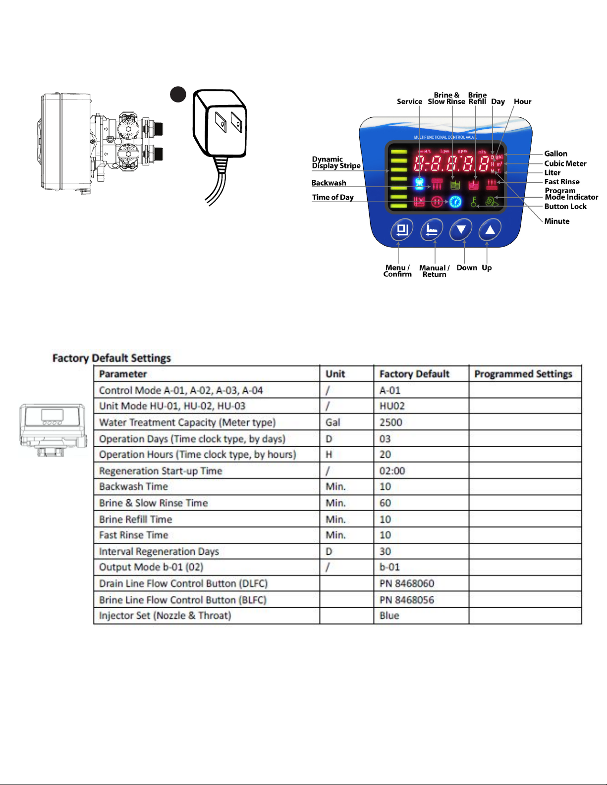
Familiarize with Button Configuration:
3.Power and Program the Valve
Attach the Transformer cable to the valve and plug in the transformer to the 110V Power outlet. you will notice the two screens on right will alternate.
6(77,1*6 83
'2:16(/(&7
6(77,1*6 83
'2:16(/(&7
6(77,1*6 83
'2:16(/(&7
6(77,1*6 83
'2:16(/(&7
6(77,1*6 83
'2:16(/(&7
KEYPAD
1
1. Connect the transformer to the valve. Plug the
12-volt transformer into a 120 VAC 60 Hz outlet.
2. Open the brine tank / cabinet salt lid and
add water until there is approximately 3”(75 mm) of water in the tank. Do not add
salt to the brine tank at this time.
STARTUP INSTRUCTIONS
After Softener installation is completed and nal adjustments are made with the water turned on and brine draw tube reconnected, manually reposition timer on softener to
backwash position. Allow timer to perform an automatic regeneration cycle. During backwash of softener, all iron cleaned from the resin will be washed down the drain. It is
advisable, after chemically cleaning softener, to regenerate system twice to fully restore capacity lost due to iron fouling.
4.

20 11
Adding Salt
Use only clean salt labeled for water conditioner use, such as crystal, pellet, nugget, button or solar. The use of rock salt is discouraged because it contains insoluble silt and sand
which build up in the brine tank and can cause problems with the system’s operation. Add the salt directly to the tank, lling no higher than the top of the brine well.
Bridging
Humidity or the wrong type of salt may create a cavity between the water and the salt.This action, known as“bridging”,
prevents the brine solution from being made, leading to your water supply being hard.
If you suspect salt bridging, carefully pound on the outside of the plastic brine tank or pour some warm water over the salt to
break up the bridge.This should always be followed up by allowing the unit to use up any remaining salt and then thoroughly
cleaning out the brine tank. Allow four hours to produce a brine solution, then manually regenerate the
softener.
CAUTION: Liquid brine will irritate eyes, skin and open wounds -
gently wash exposed area with fresh water. Keep children away from
your water conditioner.
Care of Your Softener
To retain the attractive appearance of your new water softener, clean occasionally with a mild soap solution. Do not use abrasive cleaners, ammonia or solvents. Never
subject your softener to freezing or to temperatures above 43°C (110°F).
Servicing Components
The injector assembly should be cleaned or replaced depending on the inlet water quality and water usage.
The seals and spacer cartridge should be inspected/cleaned or replaced depending on the inlet water quality and water usage.
Resin Cleaner
An approved resin cleaner MUST be used on a regular basis if your water supply contains iron. The amount of resin cleaner and frequency of use is determined by the quantity of
iron in your water (consult your local representative or follow thedirections on the resin cleaner package).
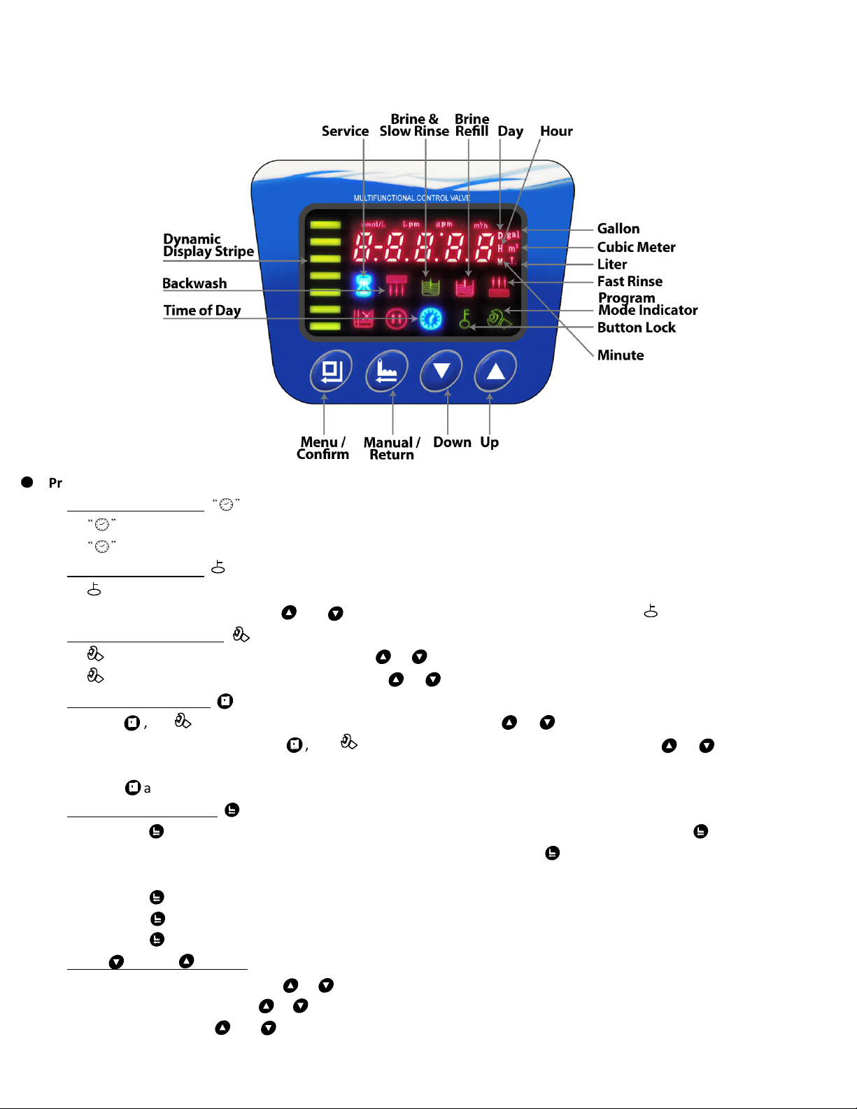
●
Programming Key
Time of Day Indicator
∗LED, displays the time of day.
∗LED flashes, reset the time of day after electrical service has been interrupted for 3 days or more.
Button Lock Indicator
∗LED on, indicates the buttons are locked.
∗To unlock, press and hold both and buttons simultaneously for 3 seconds until the LED turns off.
Program Mode Indicator
∗LED on, enter program display mode. Use or buttons to vie all values.
∗LED Flashes, enter program set mode. Press or buttons to adjust values.
Menu/Confirm Button
∗Press , the LED turns on; enter program display mode, press or to vie all values.
∗In program display mode, press , the LED flashes; enter program set mode and press or to adjust the
values.
∗Press after all program features are set.
Manual /Return Button
∗Press the button in any status and the valve ill proceed to the next step. (Example: Press the button hile the
valve is in Service status and it ill start a manual regeneration. Press the button hile in Back ash status and the
valve ill go to Brine & Slo Rinse instantly.)
∗Press the
∗Press the
∗Press the
Down and Up Buttons
∗In program display mode press or buttons to vie all values.
∗In program set mode press or buttons to adjust values.
∗Press and hold both and
button in program display mode and it ill return to In Service.
button in program set mode and it ill return to program display mode.
MASTER PROGRAMMING
12
hile adjusting the value and it ill return to program display mode directly ithout saving value.
buttons simultaneously for 3 seconds to unlock the programming functions.
●
Val e Programming Instructions
When LED is on, press and hold both and buttons simultaneously for 3 seconds to lift the button lock status.
To program the valve, press and the LED ill turn on. This indicates you are in the programming mode.
To navigate to each programming stage, press or .
To adjust that programming stage value, press and use the or to adjust the values. Follo the process steps
on the follo ing page.
To exit the programming, press and return to service status.
●
Programming and Sizing Recommendations
∗Backwash Time - A normal Back ash is bet een 10-15 minutes. The higher the turbidity a longer back ash time
should be set. Ho ever, if the turbidity is more than 5FTU it is best to install a pre-filter.
∗Brine Refill Time - The Brine Refill speed is related to inlet ater pressure and brine line flo control. It is
recommended to lengthen the calculated brine refilling time by 1-2 minutes to make sure there is enough ater
in tank. Be sure to install a safety float and shutoff in the brine tank. Refer to page 23.
∗Fast Rinse Time - Generally Fast Rinse is set for 3-6 times the resin volume; suggest at least 10 minutes.
∗Regeneration Time - The complete cycle takes about t o hours. Set the regeneration time that is convenient for
the end user; usually 2 AM.
∗Working Process - Service → 2 - Back ash → 3 - Brine & Slo Rinse → 4 - Brine Refill →5 - Fast Rinse.
Note: The display screen will display “-00-“when the drive motor is moving from one stage to the next. Each
screen displays for 5 seconds at the start of each stage.
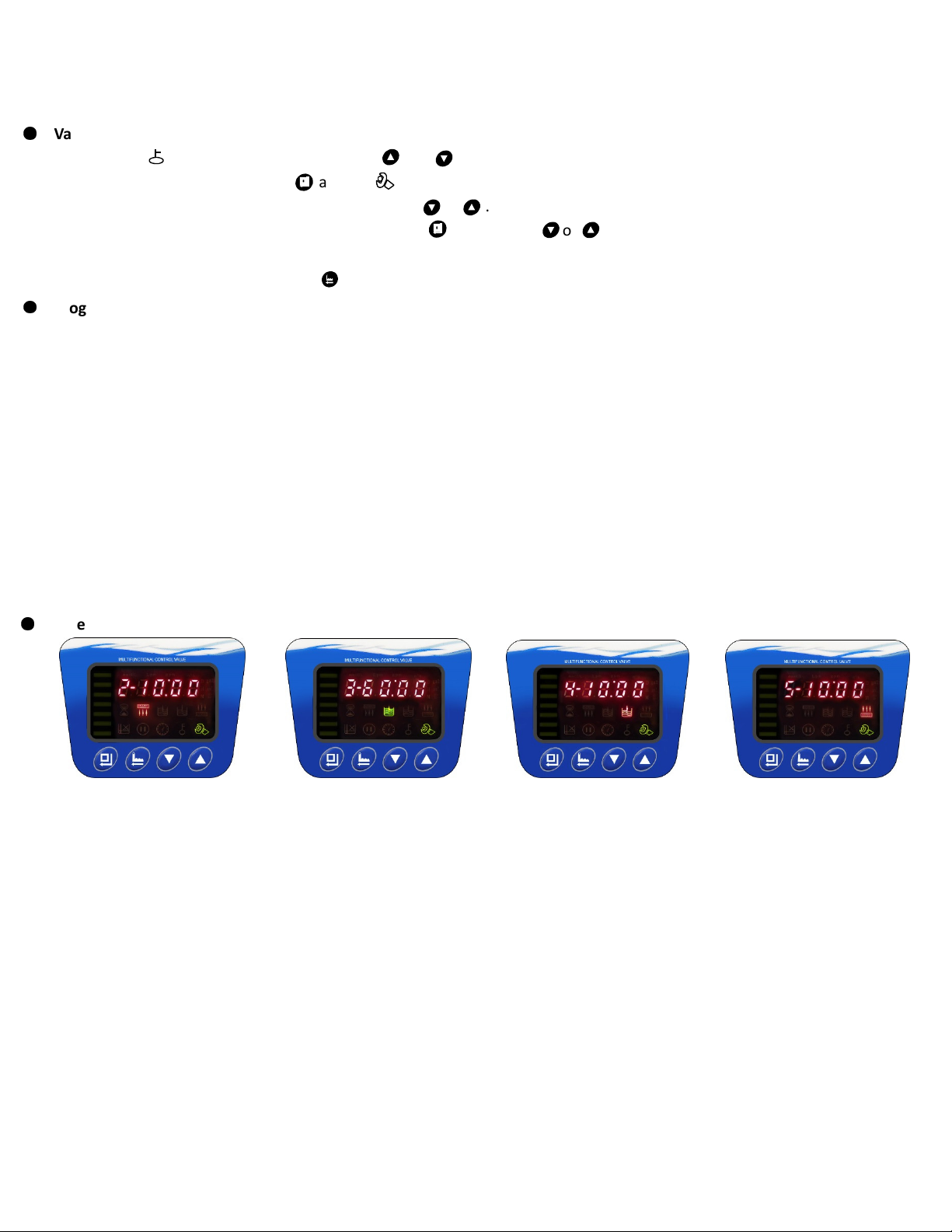
●
Val e Display
Back ash Brine & Slo Rinse Brine Refill Fast Rinse
13
MASTER PROGRAMMING

Function Indicator
Factory Default
Parameter Set Range
Instruction
Time of Day Random 00:00
~
23:59 Set the current time of day hile the “:” flashes.
Control Mode A-01 A-01
A-01 Meter Delayed. Regeneration occurs at the set regeneration time
once the gallons used reaches zero (0).
A-02 Meter Immediate. Regeneration occurs immediately once the
gallons used reaches zero (0).
A-03
Not Applicable for
U.S. Customers
Meter Delayed - set resin volume, feed ater hardness, and
regeneration factor; the valve ill calculate the system capacity.
Regeneration mode same as A-01.
A-04
Not Applicable for
U.S. Customers
Meter Immediate - set resin volume, feed ater hardness, and
regeneration factor; the valve ill calculate the system capacity.
Regeneration mode same as A-02.
Unit Mode HU-02 HU-02 01, 02, 03 01-m3; 02-gal; 03-L
Regeneration Time 02:00 02:00 00:00
~
23:59 Regeneration time. “:” light on
Inter al Backwash
Times F-00 00 0
~
20 Interval back ash times. Number listed after F indicates
number of additional back ashes bet een services.
Resin Volume 20L 20L 5
-
500L Resin volume in pressure tank (L) Only for A-03 and A-04 mode.
Not applicable for U.S. installations.
Feed Water
Hardness Yd1.2 1.2 0.1
-
9.9 Feed ater hardness (mmo1/L) Only for A-03 and A-04 mode.
Not applicable for U.S. installations.
Exchange Factor AL.65 0.65 0.30
-
0.99
Relate to the ra ater hardness. When hardness is higher, the
factor is smaller. Only for A-03 and A-04 mode. Not applicable
for U.S. installations.
Water Treatment
Capacity 2500 0-10,000
To figure capacity, take the total resin volume multiplied by .75.
Divide by grains hardness of ater supply. Example: 1 Cu/Ft =
32,000 x .75 at 15 grains hardness. (32,000 x .75) ÷ 15= 1600 gal.
Enter that value here.
Backwash Time 10 min. 0
~
99
∶
59 Back ash time.
Brine & Slow Rinse
Time 60 min. 0
~
99
∶
59 Brine & Slo Rinse time.
Brine Refill Time 10 min. 0
~
99
∶
59
Refill time is calculated based on total resin volume. Note: 1 gal
ater dissolves 3lbs of salt. Refer to bottom of page 12 for refill
time.
Fast Rinse Time 10 min. 0
~
99
∶
59
Maximum Inter al
Regeneration Days
H-30 30 0
~
40
Output Control
Mode b-01 01 01 or 02
MASTER PROGRAMMING
14
Fast Rinse time.
Forced regeneration every 30 days if no ater has been used.
Time Clock Valve: to operate as a time clock valve, set the
number of days before desired regenerat
ion.
end of regeneration.
b-
during In Service.
b-01: Signal turns on at start of regeneration and shuts off at
02: Signal available in intervals during regeneration cycles and
●
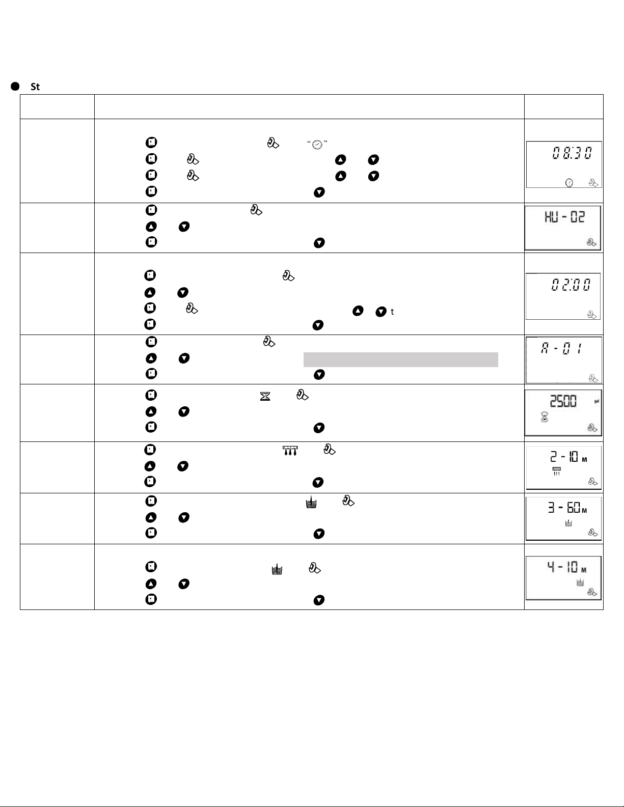
Step by Step Programming Instructions
Items Process steps Screen Display
Time of Day
Note: when “ 2: 2” flashes; Time of Day needs to be reset.
1. Press to set Time of Day; both and ill light and the “:” symbol ill flash.
2. Press , both and “H" value ill flash, press or to adjust hour value.
3. Press , both and “H” value ill flash, press or to adjust minute value.
4. Press to accept adjustments made. Press to advance to the next programming phase.
Unit Mode
1. Press to enter Unit Mode, and “02” value ill flash.
2. Press or buttons to choose HU-1 (m3) , HU-2 (gal) or HU-03 (L).
3. Press to accept adjustments made. Press to advance to the next programming phase.
Regeneration
Time
Note: No regeneration time called for in A-02 Control Mode.
1. Press to enter Regeneration Time, and “Hour” value ill flash.
2. Press or to adjust the hour value to the desired regeneration time. (24 hour clock)
3. Press again, and “Minute” value ill flash, press or to adjust minute value.
4. Press to accept adjustments made. Press to advance to the next programming phase.
Control
Mode
1. Press to enter Control Mode, and “01”value ill flash.
2. Press or to choose A-01 or A-02. A-03 & A-04 Not a ailable in the United States.
3. Press to accept adjustments made. Press to advance to the next programming phase.
Water
Treatment
Capacity
1. Press to enter Capacity; gal, and along ith the “2500” value ill flash.
2. Press or to adjust ater treatment capacity value (gal or m3).
3. Press to accept adjustments made. Press to advance to the next programming phase.
Backwash
Time
1. Press to enter Back ash Time; M, and along ith “2-10:00” value ill flash.
2. Press or to adjust the back ash time.
3. Press to accept adjustments made. Press to advance to the next programming phase.
Brine & Slow
Rinse Time
1. Press to enter Brine & Slo Rinse Time, and along ith “3-60:00” value ill flash.
2. Press or to adjust the brine time.
3. Press to accept adjustments made. Press to advance to the next programming phase.
Brine Refill
Time
Note: See instructions below to determine brine refill time needed for your size system.
1. Press to enter Brine Refill Time, and along ith “4-10:00” value ill flash.
2. Press or to adjust the brine refill time.
3. Press to accept adjustments made. Press to advance to the next programming phase.
MASTER PROGRAMMING
15
Calculating Brine Refill Time - The brine refill time is calculated based on total resin volume. For optimal efficiency… 3.0
gallons of ater are used for 9x48 (32,000 grain) system; 3.5 gal for 10x44 (40,000 grain) system; 4.0 gal for 10x54 (48,000
grain) system; 5.0 gal for 12x52 (64,000 grain) system. This example uses the recommended buttons and injectors, found on
page 8, for each size tank.
9x48- Brine Refill Time: 10 minutes (3.0 gallons/ .3 refill rate = 10) center brine float to 9# salt setting. ( hite tape)
10x44- Brine Refill Time: 9 minutes (3.5 gallons/ .39 refill rate = 8.97) center brine float to 10.5# salt setting. (blue tape)
10x54- Brine Refill Time: 10.26 minutes (4.0 gallons/ .39 refill rate = 10.26) center brine float to 12# salt setting. (blue tape)
12x52- Brine Refill Time: 6 minutes (5.0 gallons/ .83 refill rate = 6.02) center brine float to 15# salt setting. (green tape)
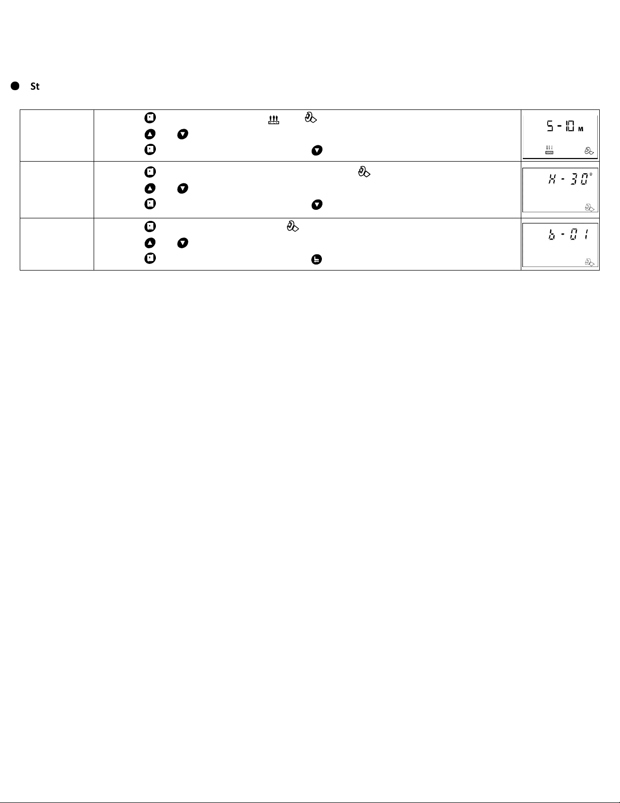
●
Step by Step Programming Instructions Continued
Fast Rinse
Time
1. Press to enter Fast Rinse Time, and along ith “5-10:00”value ill flash.
2. Press or to adjust the fast rinse time.
3. Press to accept adjustments made. Press to advance to the next programming phase.
Maximum
Regeneration
Days
1. Press to enter Maximum Interval Regeneration Days, and “H-30” value ill flash.
2. Press or to adjust the interval regeneration days.
3. Press to accept adjustments made. Press to advance to the next programming phase.
Signal
Output Mode
1. Press to enter Signal Output Mode, and “b-01” value ill flash.
2. Press or to adjust the signal output mode value.
3. Press to accept adjustments made. Press and return to service status.
16
MASTER PROGRAMMING

Tier1™
www.Tier1Filters.com
1-855-378-9116
Version 0318
Other manuals for 165 Series
1
Table of contents
Other Tier1 Water Dispenser manuals

Tier1
Tier1 WS-165-BLK User manual

Tier1
Tier1 165 Series User manual

Tier1
Tier1 RB-WS-165-132 User manual

Tier1
Tier1 WS-165-132 Series User manual

Tier1
Tier1 WS-165-150-BLK User manual

Tier1
Tier1 Elite Series User manual

Tier1
Tier1 H2-35 User manual

Tier1
Tier1 WH-HD-IRN-MG-948 User manual

Tier1
Tier1 WS-165-132-BLK User manual

Tier1
Tier1 RO5 User manual


Popular Water Dispenser manuals by other brands


GEL
GEL DECAL BASIC Operation and maintenance manual

BRIO
BRIO CLCTPOU720UVF3 Setup manual

Midea
Midea MYD10S-W manual

Prozone Water Products
Prozone Water Products PZ5 Installation guide and operation manual

Premier
Premier TH-5136 instruction manual

Smith Water
Smith Water 700 Owner's manual and installation guide