Tiger TYAA211 Operator's manual

User Instruction Manual
Dual Sliding Beam Anchor
Model # TYAA211
Model # TYAA212
Model # TYAA213
MANUFACTURED BY:
Woo Sing Industrial Co., Ltd
No 20 Yunong Road
Shih-lin
Taipei
Taiwan
Phone: +886-2-2831 3035
Fax: +886-2-2834 0188

Table of Contents
Warning and Important Notification 2
Dual Sliding Beam Anchor Components 2
Specifications 3
Applications 3
Installation and Use 5
Training 6
Inspection 6
Maintenance, Service, Storage 6
Inspection and Maintenance Log 7

WARNING:
This product is to be used as part of a personal fall protection system. The user must
read the manufacturer’s instruction and be familiar with each component of the
equipment. The user must fully understand this instruction and to be trained before using
this equipment. This equipment should not be used for material lifting or any other use
other than a fall protection system. This product is intended for one person using. Any
alteration and misuse of this equipment, or failure to follow instructions, may result in
serious injury or death.
IMPORTANT:
If you have questions on the use, care, installation or suitability of this Dual Sliding
Beam Anchor for your application, please contact your dealers, distributors, or
manufacturer for a guide.
DUAL SLIDING BEAM ANCHOR COMPONENTS
1 2
4
58
9
3
6
7
The Dual Sliding Beam Anchor consists of the following components:
1. Sliding Clamp
2. Sliding Clamp
3. Hexagonal Rod
4. End Screw w/Nylon Nut
5. Positioning ratchet for Lock Pin
6. Safety Lock
7. Quick Release Lock Pin
8. D-Ring Hanger
9. D-Ring

SPECIFICATIONS
Dimensions:
Beam Size Range, Model TYAA211: 12-in. (305mm) Maximum
2.5-in. (63.5mm) Minimum
Model TYAA212: 18-in. (457mm) Maximum
2.5-in. (63.5mm) Minimum
Model TYAA213: 24-in. (610mm) Maximum
2.5-in. (63.5mm) Minimum
Flange Thickness, Model TYAA211: 1.5-in.(38mm) Maximum
Model TYAA212: 1.5-in. (38mm) Maximum
Model TYAA213: 1.5-in. (38mm) Maximum
Materials:
All materials used in the construction of this equipment are as follows:
Stainless Steel
Anodized Alloy Aluminium
Plated Alloy Steel
Weight:
Model TYAA211: 4.26LB(1.93KG)
Model TYAA212: 4.89LB(2.22KG)
Model TYAA213: 5.53LB(2.51KG)
APPLICATIONS
Purpose:
The Dual Sliding Beam Anchor is used as an anchorage connector for a personal fall arrest system. It’s
designed to be attached on the Horizontal I-Beam. The Dual Sliding Beam Anchor might be used as an end
termination for either a shock-absorbing lanyard or self-retracting lifeline for fall arrest, or with a
positioning lanyard for fall restraint.
Limitations:
Beam Flange Sizes: The Dual Sliding Beam Anchor may only be installed on beams with flanges within
the adjustment range of the model. See the SPECIFICATION.
Capacity: This Dual Sliding Beam Anchor is designed for one person use with a combined weight
(clothing, tools, etc.) of no more than 310 lbs (140kgs). No more than one personal protective system
may be connected to this equipment at one time.

Free Fall: Personal fall arrest systems used with this equipment must be rigged to limit the free fall to a
maximum of 6 feet. The maximum free fall must always be within the manufacturer’s free fall capacity
of the system components used to arrest the fall. When a free fall greater than 6 feet and up to a
maximum of 12 feet if possible, Tiger recommends using a personal fall arrest system incorporating
with an energy absorbing lanyard.
Anchor Load Angle: Loads imposed on the Dual Sliding Beam Anchor by the personal fall arrest system
must remain within 30 degrees of the vertical centre line of the beam.
30 Maximum
Load Angle
30 Maximum
Load Angle
Anchor Load Angle
Swing Falls: Before installing or using, make consideration for eliminating or minimizing all swing fall
hazards. Swing falls occur when the anchor is not directly above the location where a fall occurs. The
user must always work as close to be in line with the anchor point as possible. Swing falls significantly
increase the possibility of serious injury or death in the event of a fall.
Swing Fall
Hazard
Swing Falls

Fall Clearance: There must be sufficient clearance below the anchorage connector to arrest a fall
before the user strikes the ground or other obstruction. The clearance required is dependent on the
following safety factors:
Elevation of Dual Sliding Beam Anchor
Length of connecting subsystem
Deceleration distance
Movement of harness attachment element
Worker height
Free fall distance
Fall Clearance Diagram
Personal Fall Arrest System: The Dual Sliding Beam Anchor is designed for use with Tiger approved
components or CE/ANSI certified components. Use of this equipment with non-approved components
may result in incompatibility between equipment, and could affect the reliability and safety of the
complete system. A full body harness must be worn by the user when connected to the Dual Sliding
Beam Anchor. When making connections with the Dual Sliding Beam Anchor, eliminate all possibility
of roll-out. Roll-out occurs when interference between a hook and the attachment point causes the
hook gate to unintentionally open and release. All connector gates must be self-closing and
self-locking.

INSTALLATIONAND USE
Installation configuration:
Bottom Mount Top Mount
Inspect the equipment according to INSPECTION of this manual before each use.
The Dual Sliding Beam Anchor could only be installed on any I-beam for horizontal position, and located on
the bottom and top of the I-beam.
Step 1. Remove the quick release lock pins. Then press the safety lock to adjust the sliding clamps.
Step 2. Place the Dual Sliding Beam Anchor onto beam flange on the bottom or top position of the I-beam.
Step 3. Place a sliding clamp against one side of the beam flange. Slide the other sliding clamp against
opposite side of the beam flange. Ensure the D-ring is at the middle position of the I-beam.
Step 4. Ensure the safety lock is in nearest position to the beam flange.
Step 5. Insert the quick release lock pins to fix the safety locks, ensuring pins are locked into place.
Step 6. Ensure the safety lock have not bottomed out. If safety lock has bottomed out, reinstall the sliding
clamp to the next locking position. If the quick release lock pin is damaged or absent, the
equipment is still in a workable condition. However for safety concerning, when one of the quick
release lock pins is damaged or absent, the equipment must be sent back to your dealers,
distributors, or manufacturer to replace a new quick release lock pin.

TRAINING
It is the responsibility of the users to assure that they are familiar with the instructions, and are
trained in the correct care and use of this equipment. Users must also be aware of the operating
characteristics, application limits, and the consequences of improper use of this equipment.
INSPECTION
Frequency:
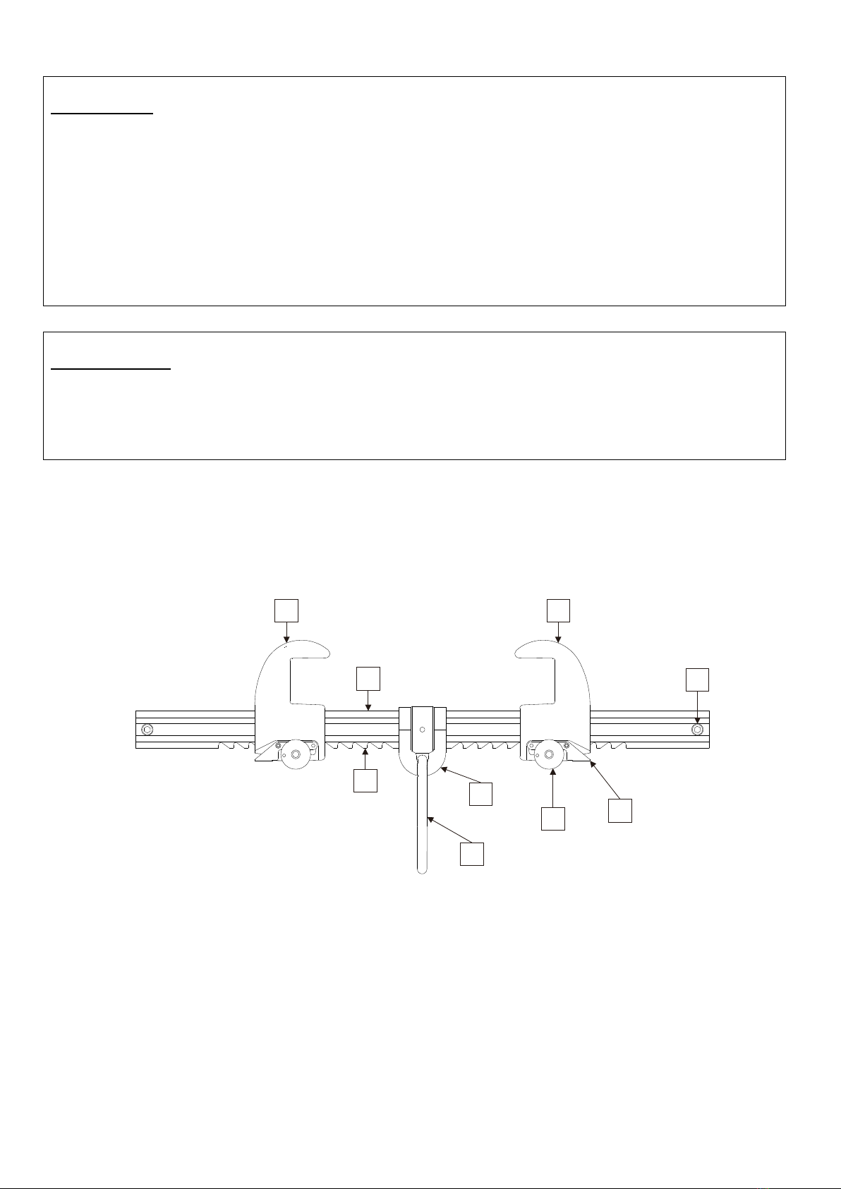
Before each use, inspect the Dual Sliding Beam Anchor according to following steps and see Dual
SLIDINGBEAM ANCHOR COMPONENTS for part identification. The Dual Sliding Beam Anchor must be
formally inspected by a competent person other than the user at least annually. Record the results in
INSPECTION AND MAINTENANCE LOG.
Inspection Steps:
Step 1.Inspect Dual Sliding Beam Anchor for damage: Look for cracks, dents, or deformities. Look for
bending or wear on the hexagonal rod, sliding clamps, safety lock, and quick release lock pin.
Ensure no parts are missing.
Step 2. Inspect entire unit for excessive corrosion.
Step 3. Ensure the quick release lock pin can be inserted through the hole on safety lock button, and
locks in place.
Step 4. Record the inspection date and results in the INSPECTION AND MAINTENANCE LOG.
If inspection reveals an unsafe or defective condition, remove the equipment from service and destroy, or
return to Tiger for repair.
NOTE: Only Tiger or parties authorised in writing are qualified to repair this equipment.
MAINTENANCE, SERVICE, STORAGE
Cleaning:
Periodically clean the Dual Sliding Beam Anchor by water and a mild soap solution. Do not use acids or
other caustic chemicals that could damage the system components. A lubricant may be applied to the
safety lock button and the quick release lock pin.
Storage:
Store the equipment in a cool, dry, dark place, chemically neutral, away from sharp corners, sources of
heat, humidity, corrosive substances or other damaging conditions.

INSPECTIONAND MAINTENANCE LOG
Company: Location: Date Purchased:
Serial Number: Model Number:
Year
Date
By a
Qualified
Person
No Missing
Parts
No Corrosion
No
Deformation
Functioning
Condition
No Changes
to
Attachment
Structure
Corrective Action
Maintenance
Performed
Corrective Action
Maintenance
Performed
Corrective Action
Maintenance
Performed
Corrective Action
Maintenance
Performed
Corrective Action
Maintenance
Performed
Corrective Action
Maintenance
Performed
Corrective Action
Maintenance
Performed
Corrective Action
Maintenance
Performed
This manual suits for next models
2
Table of contents
Popular Industrial Equipment manuals by other brands

UniData Communication Systems
UniData Communication Systems 6526 manual

S&C
S&C PureWave AVC Instructions for installation and operation

Pentair
Pentair MYERS SRA-125 Installation and service manual

THORLABS
THORLABS PWA090 user guide

Draco
Draco K9-1 instruction manual

Reflex
Reflex Reflexomat Original operating manual