TigerStop TigerSaw Miter User manual
TigerSaw Miter
Owner’s Manual
ii
Safety
SAFETY FIRST!
IMPORTANT SAFETY INFORMATION. READ ALL WARNINGS BEFORE OPERATING THIS PRODUCT.
WARNING: Installation of your TigerStop Product must be done by a person trained in the safe design and installation of
automation products, and in the safe operation of power equipment. Ensure that such installation meets all legally required
safety requirements and guidelines, and that proper guarding and safety devices are provided on all sides of the equipment to
preclude unintended access during operation. Consult with and follow the recommendations of a qualified safety engineer.
WARNING: TigerStop Products are components intended for use in conjunction with potentially dangerous machinery. The use
of TigerStop Products does not make other machinery safe. TigerStop Products are not intended to substitute, in any manner,
for safe operating practices in general, or for safety features present in other machines designed to make those machines as
safe as possible. TIGERSTOP PRODUCTS, IF USED OR INSTALLED IMPROPERLY, MAY CAUSE PERSONAL INJURY OR
DEATH AND SHOULD ONLY BE OPERATED BY PERSONS TRAINED IN THEIR SAFE OPERATING PROCEDURES. Illustrations
of TigerStop Products in use do not show, and are not intended to show, all safety features and practices necessary for their
safe operation.
WARNING: TigerStop Products must be installed in accordance with all local, state, and federal regulations. Only personnel
properly trained in the safe design and installation of automation machinery and related power equipment should install
TigerStop Products onto other equipment, to ensure a safe and proper work station. TigerStop Products should not be operated
without proper training, both in the operation of TigerStop Products, and in the operation of related equipment.
IMPORTANT CAUTION:
The motor box (compartment) contains DC voltage with potentially FATAL amperage. NEVER attempt any unauthorized actions
inside the motor box.
WARNING: Using a TigerStop interconnect does not relieve you of the responsibility for making sure that your saw or other
tool has all the necessary safety equipment in place. All installations must meet all legally required safety requirements and
guidelines. Installation and training should be done following the recommendations of a qualified safety engineer.
DANGER: This machine can start, move and stop automatically. Keep hands and loose clothing clear of moving parts while
operating. Moving parts can crush and cut. When used with a saw or other cutting equipment, bodily injury and death may result
if operated without safety guards on all machines. Do not operate with guards removed. Operators must wear adequate eye and
ear protection.
GENERAL WARNINGS
INSTALLATION WARNINGS
INTERCONNECTS
OPERATION
iii
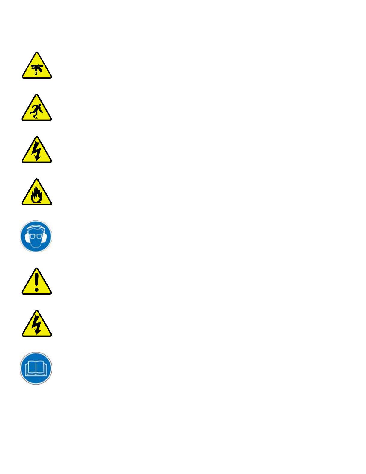
IMPORTANT SAFETY INFORMATION. READ ALL WARNINGS BEFORE OPERATING THIS PRODUCT.
DANGER! Don’t get pinched by the push feeder. Keep your hands away when in motion!
Keep the work area clean and well lighted to avoid accidental injury.
Do not operate near flammable liquids or in gaseous or explosive atmospheres!
Use only 3-wire extension cords that have 3-prong grounding type plugs and 3-pole
receptacles that accept the tools plug for 120VAC. Use only 5-wire cords and plugs
when using 3 phase.
Do not open motor compartment or controller keypad. DC Voltage with potentially
FATAL amperage! Disconnect power before servicing. No user-serviceable parts inside.
DO NOT operate this or any machine under the influence of drugs or alcohol!
No one should operate this machine except for fully qualified personnel.
READ THE MANUAL!
Do not use TigerStop machines in a dangerous environment. Using power tools in damp
or wet locations or in rain can cause shock or electrocution.
Wear proper apparel, no loose clothes, long hair or jewelry which could get pulled into
moving machinery or materials. Wear non slip footwear, safety glasses, ear protection
and a dust mask.

iv
•Treat the machine with caution and respect.
•Ensure that the machine is properly grounded.
•Keep children and untrained adults out of the work area.
•Do not leave the machine running unattended.
•Don’t force the machine to perform beyond designed rates, capacities, and applications.
•Keep the machine clean and well-maintained.
•Use forced air or a shop brush for everyday cleaning (not hands).
•Always disconnect power and follow proper lock out/tag out procedures before making adjustments or
performing maintenance work.
•Keep the power switch o while disconnected from power to prevent accidental starting.
•After performing maintenance or adjustment, remove all tools from the machine before operating.
•Properly repair or replace any damaged or missing parts, especially guarding.
•Keep saw blades sharp.
•Ensure adequate ventilation and dust extraction.
•Do not operate with insucient air pressure.
•Ensure top cap height provides adequate clearance for stock.
•Always wear steel-toed footwear when processing heavy or large stock.
•Do not remove parts from the guarded area by hand.
•Do not support material by hand during a saw cycle.
SAFETY FIRST!
IMPORTANT SAFETY INFORMATION. READ ALL WARNINGS BEFORE OPERATING THIS PRODUCT.
WARNING: Installation of your TigerStop Product must be done by a person trained in the safe design and installation of
automation products, and in the safe operation of power equipment. Ensure that such installation meets all legally required
safety requirements and guidelines, and that proper guarding and safety devices are provided on all sides of the equipment to
preclude unintended access during operation. Consult with and follow the recommendations of a qualified safety engineer.
WARNING: TigerStop Products are components intended for use in conjunction with potentially dangerous machinery. The use
of TigerStop Products does not make other machinery safe. TigerStop Products are not intended to substitute, in any manner,
for safe operating practices in general, or for safety features present in other machines designed to make those machines as
safe as possible. TIGERSTOP PRODUCTS, IF USED OR INSTALLED IMPROPERLY, MAY CAUSE PERSONAL INJURY OR
DEATH AND SHOULD ONLY BE OPERATED BY PERSONS TRAINED IN THEIR SAFE OPERATING PROCEDURES. Illustrations
of TigerStop Products in use do not show, and are not intended to show, all safety features and practices necessary for their
safe operation.
WARNING: TigerStop Products must be installed in accordance with all local, state, and federal regulations. Only personnel
properly trained in the safe design and installation of automation machinery and related power equipment should install
TigerStop Products onto other equipment, to ensure a safe and proper work station. TigerStop Products should not be operated
without proper training, both in the operation of TigerStop Products, and in the operation of related equipment.
IMPORTANT CAUTION:
The motor box (compartment) contains DC voltage with potentially FATAL amperage. NEVER attempt any unauthorized actions
inside the motor box.
WARNING: Using a TigerStop interconnect does not relieve you of the responsibility for making sure that your saw or other
tool has all the necessary safety equipment in place. All installations must meet all legally required safety requirements and
guidelines. Installation and training should be done following the recommendations of a qualified safety engineer.
DANGER: This machine can start, move and stop automatically. Keep hands and loose clothing clear of moving parts while
operating. Moving parts can crush and cut. When used with a saw or other cutting equipment, bodily injury and death may result
if operated without safety guards on all machines. Do not operate with guards removed. Operators must wear adequate eye and
ear protection.
GENERAL WARNINGS
INSTALLATION WARNINGS
INTERCONNECTS
OPERATION

v
Safety.................................................................................................................................................................................................................... ii
Contact Information.........................................................................................................................................................................................1
Installation Requirements............................................................................................................................................................................2
Power
Grounding
Air Supply
Dust Extraction
TigerStop Controls..........................................................................................................................................................................................3
Saw Operation...................................................................................................................................................................................................4
System Power
Saw Control Panel
Access Doors and Safety Switches
Integration & Automation .............................................................................................................................................................................7
Components
Breaking the Safety Chain
Resetting the Safety Chain
Interconnect Behavior
Basic TigerStop Operation ..........................................................................................................................................................................9
Controller Display
Soft Keys
Home Routine
Ready Screen
Manual Movement
Calculator
Increment
PreSet
Jog
Quick Calibration
The TigerStop Menu .....................................................................................................................................................................................14
Menu Selection
Home
Calibrate
Kerf
Find End Limits
Minimum Limit
Scale
Password
PreSet Behavior
Millimeter Conversion
Disable Quick Calibration
Units
Jog Reverse
TIK (Tool Interconnect Kit)
Table of Contents
Table of contents
Other TigerStop Saw manuals


