Tigertronics BayPac BP-96A Guide

BayPac BP-96A Packet Modem
154 Hillview Drive Grants Pass, Oregon 97527
(541) 474-6700 Fax: (541) 474-6703 Internet: http://www.tigertronics.com
Installation & Operation
- INTRODUCTION -
The Model BP-96A is an enhanced version of the BayCom
Team's 9600 Baud PICPAR modem, which is sold in
Germany as a kit. The Tigertronics version of this modem
employs "surface mount technology" and comes completely
assembled and tested. This superior technology permits use
of robotic assembly, resulting in a vastly smaller unit with
enhanced reliability and lower cost. Power consumption has
also been improved. In fact, power consumption is now so
low, that the BP-96A can get all of it’s operating power from
your computers parallel port!
It should be noted that installation and setup of ANY High
Speed Modem requires some technical expertise and access
to the proper test equipment. Operation at 9600 baud is
much less “forgiving” than 1200 baud, so proper adjustment
of both receive level and transmit deviation is critical for
reliable operation. You will need a radio that is “9600 baud
ready” or one that has undergone appropriate modification
for high speed operation. Normal “voice grade” radios will
not work properly without extensive modification. These
instructions assume that your radio is “9600 baud ready”.
Installation of the BP-96A is a two-step process. The first
step involves connecting the unit to your radio and computer.
This document will help you through that process. The
second step involves setting the transmit audio level. In
addition, you will of course need to install BayCom
compatible TNC emulation software on your computer.
Currently, only BayCom v1.6 supports 9600 baud operation.
If you did not obtain Version 1.6 when you purchased your
modem and do not already have a copy, you will need to
purchase it separately from the authors or from Tigertronics.
Note that previous (Shareware) versions of BayCom did not
support 9600 baud operation and WILL NOT work with this
modem.
- WHAT YOU WILL NEED -
To run the software you will need a 10 MHz (or faster) IBM
AT compatible computer, with a parallel interface port.
Normally, the BP-96A should be plugged directly into the
parallel port connector on the computer. If you wish to
attach the BP-96 to a cable or switch box, you should use a
cable that us FULLY SHIELDED and no longer than 3 feet.
A cable is supplied with the modem for connecting to your
radio. It has a DB-9 male connector on one end. You will
need to install whatever connector is appropriate for your
radio on the other. If your computer can not supply
sufficient power to the modem, then you will also need an
external power source of 8-14V DC at approximately 10ma.
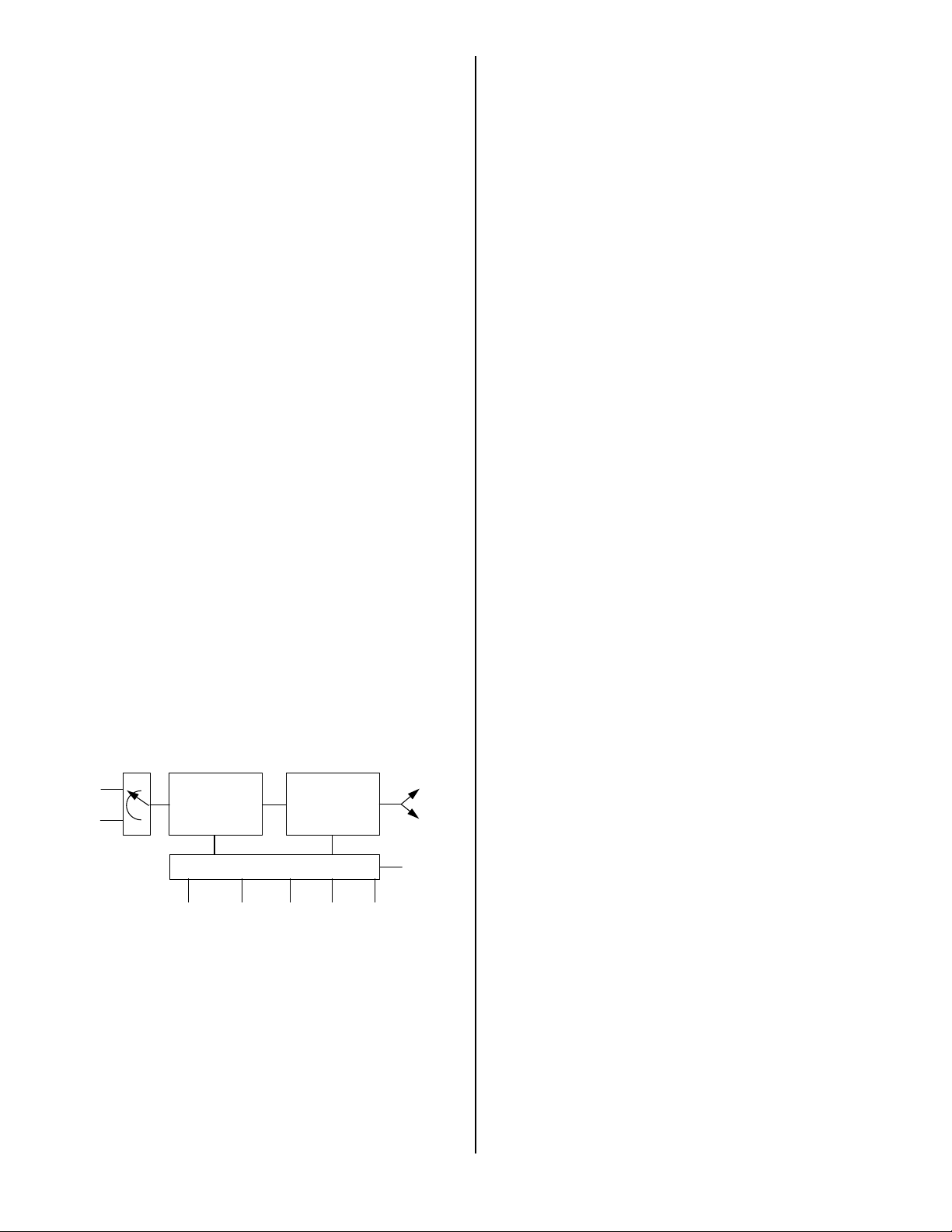
- BP-96A BLOCK DIAGRAM -
Figure 1 shows a block diagram of the BP-96A modem. The
modem is connected via six signal lines to the Centronics
interface on the PC. The transmission of the RX and TX
data is done serially since the Centronics interface has only
four input lines.
PC
PTT
DCD
CLK/16
TXD
RXD
D/A
Converter
Analog
LP-Filter
Analog
LP-Filter
FIR-Filter
PIC 16C84
To
Modulator
From
Demodulator
BURST
Data - FIFO
DCD
Clock Recovery
Data -
Reconstruction
Printer Port
Figure 1 - Block diagram of the BP-96A modem.
Grants Pass, Oregon
2
The RX and TX data is transmitted in 16 bit bursts each via
the interface. The sixteen bits of TX data are written via
TxD into the modems TX buffer (shift register). This data
transfer is controlled by the BURST line. Once in the TX
buffer, the bits are clocked out by the TX clock and sent
through a digital filter. An analog filter removes the
unwanted sampling signals from the digital filter. Although
necessary for a G3RUH-compatible signal, the data is not
scrambled in the hardware. This is done in the software,
such that the data reaching the modem is already scrambled
and NRZI coded.
On the RX side, the demodulated AF from the receiver is fed
into a low pass filter and then into a binary discriminator.
The discriminator compares the signal with the average of
the bit stream (which consists of approximately as many
binary ones as zeros). The raw data bit stream now needs to
be sampled at the right time, i.e., in the middle of each bit.
To do this, the clock of the received signal is recovered by a
digital phase locked loop circuit (implemented in the
PIC16C84). The raw data bit stream is then sampled at this
clock rate and fed into the RX buffer. The CLK/16 line then
tells the PC that the RX buffer is full and should be read
again by the BURST line.
- THE INTERFACE -
The buffering and the burst transfer of data between the
modem and the PC is the most complex part of the modem.
The interface circuitry is used for both TX and RX data.
The direction of the data is determined by the PTT signal, so
the modem will only support semi-duplex operation. Figure
2 shows a block diagram of the interface circuitry. The
interface consists of two shift registers connected in series,
and a control circuit which generates the clock signals for the
shift registers and toggles the direction of data flow.
16 bit shift register
SR1 SR2
16 bit shift register
Interface
PTT BURST RXCLK TXCLK Aux. CLK
CLK/16
TxD to
Modem
RxD to PC
RxD from
Modem
TxD
from PC
CLK CLK
Figure 2 - Block diagram of the interface.
During transmission, the PC sends 16 bits of TX data into
SR1 via a serial line, controlled by the BURST signal. At
the same time, SR2 is being read bitwise by the modem at a
rate determined by the modem's TX clock. Once SR2 has
been emptied, the contents of SR1 are shifted into SR2 at
high speed. Then, the CLK/16 line signals the PC that SR1
has been emptied and that another 16 bits of TX data may be
written into SR1 with the burst signal.
During reception, the functions are reversed. The
regenerated RX clock writes RX data into SR1. After 16
clock cycles, SR1 is full and its contents are transferred to
SR2 at high speed. The PC is then signaled with the CLK/16
line that SR2 is full, and can be read using the burst signal.
The complete control circuitry is built using a PIC16C84
microcontroller. All control signals for the shift register
toggling and the data transfer between the shift registers are
derived from the RX and TX clocks as well as the BURST
signal and an 1.228 auxiliary clock. A 4517 dual shift
register is used for the RX and TX buffers.
- THE TX BRANCH -
During transmission , the TX data bits in SR2 are shifted into
another 8-bit shift register. This shift register then makes the
bits available to the PIC16C84 microcontroller. The
PIC16C84 digitally filters the TX data bits and converts
them from digital to analog. The analog signal is then fed
into a low pass filter (IC5) which removes the high
frequency components from the converters output. C16 then
removes the DC offset (which can lead to an RX shift in
some radios), and the signal is sent to the radio for
transmission.
- THE RX BRANCH -
During reception, the received signal is passed through a low
pass filter (IC4A), and then to IC4B, which acts as a
discriminator. The output of IC4B is then passed to the
PIC16C84 microcontroller (IC3), where the receive clock is
recovered. The PIC16C84 then passes the raw data to the
computer via the parallel port.
- AUXILIARY CIRCUITS -
The BP-96A can be powered by either the computers parallel
port, or by an external power supply. If an external power
supply is used, then the external power (8-14 V DC) is shunt
regulated (by R1, R2 and D1) to a constant 4.5 volt level.
Power obtained from the parallel port is not regulated, since
the voltage levels on the parallel port are no more that 5
volts.
The radios PTT line is controlled by a FET transistor (Q4)
capable of sinking about 75ma at 12 volts. This transistor
keys the radio by shorting the PTT line through ground. If
your radio needs some other keying arrangement (not likely),
then you will need to provide it. If your radio is an older
model with high voltage or high current on the PTT line, you
will need to install a small relay to do the keying.
- INSTALLATION -

3
The installation of the modem is relatively strait forward.
But, before you begin, be sure you have reviewed your
radios documentation to verify that it is 9600 baud
compatible and that you have the correct connectors on hand
to interface to it. You will also want to check your
computers manual to determine the address and interrupt
number for the parallel port you intend to use. The BayCom
software defaults to the “standard” parallel printer port
(LPT1). Be sure that you have thoroughly read the BayCom
v1.6 software documentation before proceeding.
- CONNECTING THE COMPUTER -
The modem can be plugged directly into the PC parallel port
connector or attached with a “Centronics” type extension
cable (DB-25 male to DB-25 female). The cable should be
as short as possible and under no circumstances should it be
longer than 3 feet. Note that many “Serial” cables of this
type DO NOT contain all the necessary lines. If you wish to
construct your own cable, only the wires shown in Figure 3
need to be wired:
1
14
13
25
2 = TxD 3 = PTT 4 = BURST 10 = CLK/16 12 = RxD
18-25 = GND
- - - - - - - - -
13 = DCD
Figure 3 - Wiring of the Centronics cable.
The male DB-25 connector on the cable is plugged into the
parallel port of the computer (like a printer would be).
- CONNECTING THE RADIO -
All wires required for connecting the radio to the modem are
available on the DB-9 connector on the front of the modem.
5 = RX-AF 3 = PTT 1 = TX-AF
6-9 = GND
5 1
9 6
Figure 4 - Wiring of radio connector.
At this stage it is appropriate to mention that most radios
must be converted for 9600 baud operation. So far (mid-
1997), only a few radios are available commercially that
allow for the direct connection of 9600 baud FSK modems.
When choosing a radio, please keep in mind that the rx/tx
switching time on most synthesized radios is very long and
will therefore limit throughput since you will require a rather
long TX Delay setting. The PTT line is active low
(grounded during transmit).
- CONNECTING THE MODEM -
Connect the modem to the radio with the appropriate
cabling. Next, turn on the computer. In rare cases, it is
possible that the radio will go into transmit mode
immediately. This is because sometimes the computers
parallel port powers up without resetting it’s output lines. If
this happens, simply turn off the radio until BayCom
software is installed and running.
- SOFTWARE INSTALLATION -
Before you can operate the modem, you will need to install
BayCom v1.6 (or higher) on your computer. To install the
BayCom software, insert the program disk into your floppy
drive and type A:INSTALL. Follow the on-screen
instructions and the software will be installed and configured
for LPT1. If you wish to install the modem on a different
printer port, you will need to manually edit the SCC.INI file
after installation is complete. Refer to the BayCom manual
for instructions.
- STARTING BAYCOM -
Start the program by entering L2 at your DOS-prompt (make
sure that the BAYCOM directory is your working directory).
There should be an all-English message and a flashing
rectangle in the upper right corner of the screen. If this is
the case, just enter SCC at the prompt and the familiar
BayCom screen should appear. If a message appears whose
last line is in German, it means that the software could not
detect the modem. Exit and restart L2 again. If the modem
still isn’t detected, then you should recheck your cables and
verify that you have selected the correct parallel port,
interrupt and base address in the software.
Lets assume that all goes well and the BayCom screen
appears. Turn on your 9600 baud radio and set it to a packet
frequency. If there is traffic on the frequency you should
now be able to monitor it in the bottom window.
- ALIGNMENT -
A proper alignment will be easiest if you have an
oscilloscope. But, if an oscilloscope is not available, you
should have little difficulty doing the alignment without it.
Before you start you will need to make a few changes to your
station setup. IF your radio is a high-power synthesized
radio (anything above 2 watts is high-powered), set your
DWAIT on the channel in question to about 20 to allow for
long switching times.
Set TXDELAY to 200 and switch to a monitor port by
pressing F10. You can now send unproto packets by simple

4
pressing ENTER. Have another radio tuned to the transmit
frequency and keep it unsquelched. Now adjust the Level
control on the front of the modem so that the noise level of
the test packets is just below the normal channel noise. If
you have an oscilloscope or millivolt meter you can consult
your radio manual for the signal level required to produce a
3KHz shift at the radios modulator. Adjust the level as
required. This is best done with a deviation meter since the
deviation is critical for reliable operation.
After you have adjusted the transmit audio level, you need to
find a good station to connect to. If you see another stations
packets on the monitor you probably will be able to connect
to them. While still in the monitor window, enter
:c callsign
Now send an unproto test packet by pressing ENTER in an
empty line. If the station receives your packet, the station
will respond with a packet with a DM,F at the end. If you
get no response, try again, a few times if necessary. If you
get no response at all try it again with a slightly longer
TXDELAY or a better antenna location. If the DWAIT (the
time that your partner station will wait before responding if
you have just transmitted - DWAIT is the relevant BayCom
parameter for this) at your partner station is too low and you
are using a synthesized radio, this could be a problem. If all
(or an overwhelming majority) of your packets get
acknowledged, your ready for the next step. Now, using the
same method as above, try and lower your TXDELAY as far
as you can without increasing the number of unanswered
packets. Once you get the TXDELAY as low as you can
(while maintaining good performance), record this value and
enter it into your SCC.INI file.
- RF INTERFERENCE -
The BP-96A modem was designed with RF immunity in
mind. Not only is its circuitry designed to minimize the
generation of radio emissions, but it is also designed to
suppress emissions from your computer. Nevertheless, if
you operate the unit in the presence of excessively high RF
fields (HF Kilowatts), you are probably going to have
problems with both the computer (especially laptops) and the
BP-96A. RF induced problems are easily identified since
they generally cause the modem and/or computer to become
totally inoperative (lock up) after transmitting. If this
happens, you can reset either device by removing power and
then restarting the program. WARNING: Excessively high
levels of RF can permanently damage your equipment.
- QUESTIONS & ANSWERS -
Can I run the BP-96A and a BP-2 at the same time?
Yes, provided that your computer is fast enough. All that
needs to be done is to enter the appropriate interface
numbers and parameters for each modem during the
installation procedure.
There is no flashing rectangle after starting the program
with L2.
This can occur because of various reasons. First make sure
that the interrupt you are using is not being used by another
device. Did you make the computer to modem interface
cable? If so, check the cable for any crossed, shorted, or
broken wires. Have you wired the right pin numbers?
I see the flashing rectangle, but only after I start L2 a
second time.
This problem can occur on older computers that have “weak”
parallel ports. When L2 starts, it switches on the computers
parallel port (which powers the modem). If the parallel port
doesn’t turn on fast enough, then the modem isn’t able to
respond to the L2 program in time, and you get an error
message. When you start L2 a second time, the parallel port
is already switched on, so the modem responds and you get
the flashing rectangle. This is not an issue if you are using
an external power supply on the modem.
My signals are not received properly by other stations.
Such problems are frequently due to radios that are not
suitable for 9600 baud operation. This often includes
synthesized radios that have been converted. Please check
the connections between the radio and the modem carefully.
Other problems include too low of a TXDELAY, or
incorrect deviation. Also make sure that you have enough
DWAIT to allow other stations to go back to receive mode
after they transmit. Under no circumstances should you
simply scale the parameters that you have used for 1200
baud operation!
The L2 rectangle flashes, but I cannot hear a signal, just
a carrier.
Verify that the Level control is not turned down all the way.
See the ALIGNMENT section if the transmit audio level has
not been adjusted yet.
The L2 rectangle flashes, but I cannot receive.
Are you sure there is traffic on the frequency? Check all
connections to modem, radio, and PC. Make sure that you
are on a 9600 baud frequency. Note that 9600 baud
transmissions sound like bursts of noise (nothing like 1200
baud!).
- VISIT US ON THE WORLD WIDE WEB -
If you have Internet access, please visit our Page on the
World Wide Web at: http://www.tigertronics.com This
site contains the latest news about Tigertronics products, as
well as a wealth of information of interest to all Hams and
SWL’s. This site is also your best source for the latest
updates to all of our software.
- YOUR COMMENTS WELCOME -

5
Tigertronics has made every effort to make the BP-96A the
best possible product. We believe it represents a major
technological breakthrough in packet radio and hope we
have anticipated your every need in using it. We welcome
any comments or suggestions that you would like to make.
Please drop us a note to let us know about your experiences,
tips you would like to share with other users, or how we
might do a better job.
- LIMITED WARRANTY -
Tigertronics warrants the BayPac Modem to be free of
defects in material and workmanship for a period of 90 days
from the date of shipment. Tigertronics will repair or
replace, at its option, any parts found to be defective during
the warranty period. This warranty does not include any unit
which has been subject to misuse, neglect, improper
installation or operation. This warranty is in lieu of all
others, express or implied, and no person or representative is
authorized to assume for Tigertronics any other liability in
connection with the sale or use of this product. Tigertronics
will not be responsible for any expense or loss of revenue or
property incurred by the user due to operation or malfunction
of this equipment. Tigertronics reserves the right to make
circuit or component changes, or to incorporate new features,
at any time, without obligation.
- RETURN POLICY -
A Return Material Authorization Number (RMA#) must be
obtained from the factory before any product will be
accepted for return or repair. Items received at the factory
without an RMA# clearly marked on the OUTSIDE of the
package WILL BE REFUSED. Items being returned must
be sent prepaid. Returned items should have a note attached
showing the RMA#, customer name, return address, phone
number, and action requested. Units being returned for
warranty repair must be accompanied by a copy of the
original sales invoice showing the date of purchase.
Customers wishing to return a product for REFUND, for
ANY REASON, must receive an RMA# within 15 days from
the shipping date shown on the original sales invoice.
Customers returning products for refund will be charged a
Restocking Fee equal to 20% of the purchase price, to cover
the cost of re-testing and re-stocking. Products which have
been damaged or modified in any way, may not be returned.
Contact our Technical Support department for the RMA#.
- TECHNICAL SUPPORT -
If you encounter problems that you cannot resolve with the
BayPac (not software), you can reach our Technical Support
Center at (541) 862-2639 any Monday, Wednesday, or
Friday between 1:00 PM and 5:00 PM (PST). Be sure to
have your equipment available for testing when you call.
Also, have a printout of your AUTOEXEC.BAT and
CONFIG.SYS files available for review. Please DO NOT
mail, email, or fax your technical inquiries to us. We realize
that calling is a little more expensive, but more can be
accomplished in a few minutes on the phone than can be
done in hours of writing! We simply are not able to respond
to written inquiries involving technical problems.
- SPECIFICATIONS -
Compatibility: G3RUH 9600 baud DFM
PAR9600 / PICPAR / BP-96
Computer Interface: Centronics Parallel Port
Power: Computer Parallel Port (5ma) or external power
source of +8 to 14 volts @ 10ma
Signals: PTT (active low) 75ma @ 12v (MAX).
Rx Input 300mv p-p (nom)
Tx Output 0 - 3v p-p
Connectors: Parallel Port - DB-25M
Radio Port - DB-9F
Power - 5.5 x 2.1 mm (Center +)
Size: 7/8” H x 2-1/4” W x 3” D
Case: Molded ABS - Gray/White
Construction: Surface Mount Technology (SMT)
Accessories: DB-9M radio cable
5.5 x 2.1 mm power plug
(C) 1997 All Rights Reserved BayPac is a trademark of Tigertronics, Inc.
(Rev. 10/10/05)
Table of contents


