AvaLAN AW5802xTP User manual

User’s ManUal
Industrial-grade, long-range wireless Ethernet systems
AvaLAN
WIRELESS
5.8 GHz Outdoor Wireless Ethernet Panel
AW5802xTP

AW5802xTP User’s Manual
PAGE 2
Technical Support (650) 384-0000 www.avalanwireless.com
© by AvaLAN Wireless Systems Inc. All rights reserved.
Revision 02.05.2013
125A Castle Drive
Madison, AL 35758
Sales: (866) 533-6216
Technical Support: (650) 384-0000
Customer Service: (650) 641-3011
Fax: (650) 249-3591
Thank you for your purchase of the AW5802xTP 5.8 GHz Outdoor Wireless Ethernet Panel. This unit
is intended for use with other AW5802 Family products to form point-to-point or point-to-multipoint
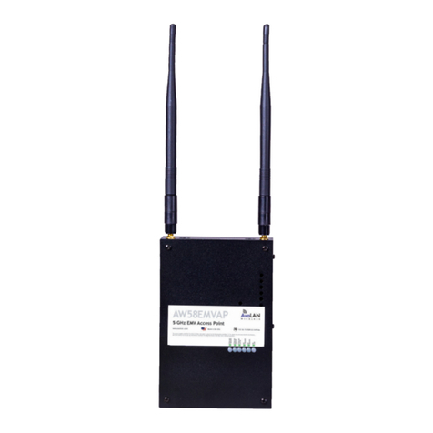
wireless Ethernet systems. It features an integrated directional 22 dBi at panel antenna. It is not
compatible with AvaLAN’s older AW5800 Family or the high speed AW58100 Family.
The AW5802xTP includes:
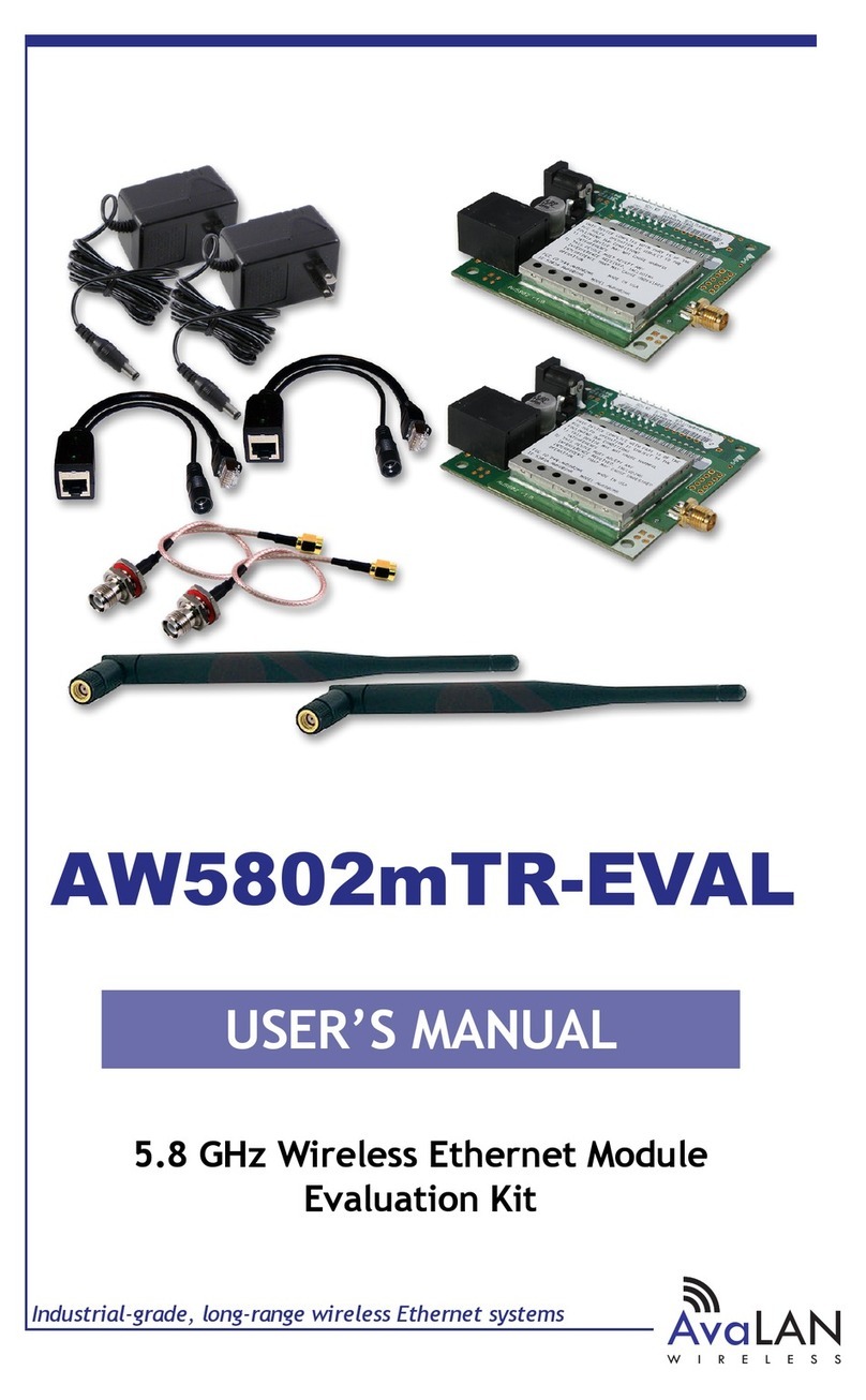
• (1) AW5802xTP Integrated Antenna & Radio
• (1) 120 VAC to 12 VDC power adapter
• (1) AW-POE Power Over Ethernet Injector
• (1) Pole Mount Bracket
Table of Contents
Quick Start Guide . . . . . . . . . . . . . . . . . . . . . . . . . . . . . . . . . . . 3
Operational Summary . . . . . . . . . . . . . . . . . . . . . . . . . . . . . 5
Physical Setup . . . . . . . . . . . . . . . . . . . . . . . . . . . . . . . . . . . . . 6
Digital Conguration . . . . . . . . . . . . . . . . . . . . . . . . . . . . . . . . . . . . . 7
Radio Status Information . . . . . . . . . . . . . . . . . . . . . . . . . . . . . . . . . . 11
Technical Specications . . . . . . . . . . . . . . . . . . . . . . . . . . . . . . . . . . . 12
Frequency Channels . . . . . . . . . . . . . . . . . . . . . . . . . . . . . . . . . . . . . 13
Warranty and Regulatory Information . . . . . . . . . . . . . . . . . . . . . . . . . . 13
If you have any questions when conguring your AvaLAN system, the best place to get answers is to
visit www.avalanwireless.com. You will also nd the latest documentation and rmware updates
To speak to a live technician, please call technical support at the number below during normal busi-
ness hours.

AW5802xTP User’s Manual
PAGE 3
Technical Support (650) 384-0000 www.avalanwireless.com
Quick Start Guide
To create a wireless link, you need one AW5802xTP congured as a master (Access Point) and one or
more AW5802xTP radios congured as clients (Subscriber Units). We recommend connecting and pow-
ering up the units on the bench before deploying in the eld because it is much easier to troubleshoot
problems and to adjust the conguration if necessary without having to climb poles to do it. Activate
the AW5802xTP units one at a time until they can be given distinct IP addresses.
Step 1. Gather the parts: In addition to the AvaLAN radios, the accompanying AW-POE Power Over
Ethernet Injectors and 12 VDC Power Adapters, you will need a CAT5 cable and a PC with a LAN
connection.
Step 2. Make the connections: Connect a radio to the PC as shown in the diagram. Plug in the power
supply to turn on the radio.
Step 3. The default IP address of the radio is written on its product label. This default address is usu-
ally 192.168.17.17. The default login password is “password.” You must congure your PC’s wired LAN
port to the same subnet and an IP address dierent from this one. With this conguration in place,
you should be able to use a web browser on your PC to log in to the radio’s interface.
Step 4. If you are not able to change your PC’s LAN conguration (usually because of an in-
compatible subnet), another method is available to change the radio’s IP address to some-
thing your PC can browse to. Download the AvaLAN IP Finder Utility from our website:
http://avalanwireless.com/marketing_resources/downloads/ipnder.zip. Unzip to a folder of your
choice and run ipnder.exe (a stand alone executable). You should see a window similar to that shown
on the next page:

AW5802xTP User’s Manual
PAGE 4
Technical Support (650) 384-0000 www.avalanwireless.com
The AW5802xTP should appear in the list, showing you its MAC Address, IP Address, etc. If it does not,
click “Search” to regenerate the list. If it still does not appear, you have a connection issue and need
to re-examine the cabling. If it does appear in the list and you wish to change the IP Address, double
click the radio’s line in the list and a second screen will appear that allows you to change the address,
subnet mask and gateway.
Step 5. Using your favorite web browser on the PC, browse to the IP Address of the radio:
http://192.168.17.17 [ or whatever IP Address has been congured ]
This screen should appear:
Step 6. Repeat the above process for each of your AW5802 Family radios, making sure to give each
one a unique IP address and making note of the addresses assigned. Once you have veried that all
radios can be browsed to, proceed to the detailed conguration steps in this manual.

AW5802xTP User’s Manual
PAGE 5
Technical Support (650) 384-0000 www.avalanwireless.com
Operational summary
The AW5802xTP Radio allows the user to create a long-range, wireless Ethernet network with up to
16 subscriber units per access point. The conguration may include any combination of AW5802xTP,
and AW5802xTP radios. A frequent conguration would include an AW5802xTR with its omnidirectional
antenna as the Access Point, with several AW5802xTP directional radios as Subscriber Units with their
directional panel antennas pointed toward it.
Conguring a wireless link with the AW5802xTP requires the establishment of seven elements:
• Each radio must know whether it is to be an access point (AP) or subscriber unit (SU).
• Each radio must have an IP address that is unique among all others on the same network.
• The AP must know how many SUs are expecting communication with it.
• The AP and all SUs must agree on which radio frequency channel they are using. This can be
manually set or allowed to change automatically.
• Each SU must be assigned a unique subscriber ID to specify which time division slot it will use
when communicating with the AP.
• The AP and all SUs must share a common 8 digit hex Network Name.
• The AP and all SUs must share a common 32 digit hex encryption key.
AW5802xTP radios are congured by connecting to a computer that will run a web browser and set-
ting parameters via their built-in browser interfaces. This browser interface also provides link quality
statistics and a graphical spectrum scan to assist in setup and resolving connection problems.
The access point (AP) automatically scans for the best of the 59 available radio frequency channels,
encrypts Ethernet data received from the network, and transmits it wirelessly to the correct sub-
scriber unit (SU). The AP is constantly monitoring the radio link and can automatically change the
channel if performance is degraded due to interference. If two AP units are very close to one another,
they may interfere with each other if operating on adjacent frequency channels. Place them at least
10 feet apart or manually select non-adjacent channels for their operation. Also, the SU should be
placed at least 10 feet from the AP while testing to avoid overloading the radio’s receiver.
Any 10/100 BaseT Ethernet client device (ECD) can be connected to an AW5802xTP subscriber unit.
Each SU encrypts Ethernet trac received from the attached ECD and transmits the data wirelessly
to its AP. Each SU can be plugged directly into an ECD without adding drivers or loading software.
Essentially, once the AP/SU pair is congured and running it behaves like a continuous Ethernet cable.
The Ethernet packets that are transmitted over the wireless link are encrypted using FIPS 197 vali-
dated 128-bit AES. They are also provided with error correction to make sure that the information
is received correctly. Each packet is divided into smaller sub blocks. This step improves overall data
rate because an error in one sub block can be detected and corrected without needing to retransmit
the entire packet. If an erroneous sub block is received, a retransmit is requested. For this re-trans-
mitted sub block, Forward Error Correction is applied, adding enough redundant bits to the data to
allow recovery of up to 3 bits in every 16. This FEC sub block is much larger and consequently takes
longer to transmit but has a very high probability of being received correctly. Of course, if the inter-
ference is great enough, this robust error correction scheme will still fail. Retransmission of bad sub
blocks will be attempted 3 times before reporting a packet failure.

AW5802xTP User’s Manual
PAGE 6
Technical Support (650) 384-0000 www.avalanwireless.com
Physical Setup
Step 1. Before mounting the radio in its nal location, you may want to perform the digital congura-
tion procedure described in the next section.
Step 2. Mount the AW5802xTP securely using the mounting bracket provided or other means as neces-
sary. Maximize lightning resistance by providing a strong DC ground connection to the metal housing.
Step 3. The unit may be mounted with horizontal or vertical polarization and it is important that the
antenna of the Access Point and the antenna of the Subscriber Unit be pointed toward one another
and be oriented with the same polarization. The polarization direction is indicated on the product
label. Use care in aiming because the antenna beam width is only about 10º.
In a point-to-multipoint situation with radially dispersed SUs, you should use an AW5802xTR equipped
with an omnidirectional antenna as the Access Point. Its antenna should be oriented parallel to the
polarization direction of the AW5802xTP panels.
Step 4. Power is provided to the unit by means of the Ethernet cable, allowing the power supply to
be located at a convenient location. The included power-over-Ethernet injector (POE) provides the
means for adding DC power to unused wires in the cable. It is most convenient to plug the male RJ-45
connector of the POE directly into your LAN switch or peripheral device and the accompanying power
supply into a 120 VAC outlet near by. The LAN cable to the radio plugs into the female RJ-45 jack and
will carry DC power to it. The AW5802xTP is provided with a cable clamping device that allows an
RJ45 plug on the cable to pass through it and can be tightened down around the cable to provide a
weatherproof seal.

AW5802xTP User’s Manual
PAGE 7
Technical Support (650) 384-0000 www.avalanwireless.com
Digital Conguration
This section of the manual assumes that you have successfully powered up a radio and are able to
browse to its IP address as discussed in the Quick Start Guide earlier.
Login: Browse to the radio you wish to designate as the master (Access Point) rst. This login page
should appear:
This initial page presents many useful pieces of information: operating statistics, current radio con-
guration and rmware version numbers.
The default login Password is “password”. Enter it into the box in the top right corner of the login
page and click “Login” to go to the Admin page. If you have changed the password and have forgotten
what it is, the only way to recover is to remove the radio’s cover, being very careful not to damage
the water tight gasket. With the radio powered on, press the small white reset button on the PC board
and hold it for at least 5 seconds. This resets the radio to the factory default IP address and password.

AW5802xTP User’s Manual
PAGE 8
Technical Support (650) 384-0000 www.avalanwireless.com
Admin Page Settings: The Admin page has Statistics and Device Information sections similar to the
Login page plus the addition of several new sections.
Device Settings: Here you may change the Login Password, select the RF Channel to use (or enable
Automatic Channel Mode) and modify the Network conguration.
RF Channel selection: In Automatic Channel Mode, the Access Point radio will choose a channel based
on avoiding interference from other RF sources, changing it as necessary if block error rates rise.
The Subscriber Units will search for and select the frequency channel used by the Access Point. If
you have multiple AW5802 Family Access Points operating in the same vicinity or other known sources
of interference, choose a channel manually. We recommend also setting the Subscriber Units paired
with each Access Point to the same channel so that they won’t have to hunt for it.
Spectrum Scanner: Scrolling down on the Admin page brings you to the Spectrum Scanner as shown
here:
The Spectrum Scanner controls are self-explanatory. Executing a scan interrupts data ow, so you
will normally want to turn automatic scanning o. Please note that this Spectrum Scanner works well
with Internet Explorer and Firefox browsers, but may not work with Chrome or Safari due to browser
javascript dierences.
MAC Address Routing Table: Another section visible in this screen shot is the MAC Address to Device
ID Routing Table. If radios are linked, this information allows you to determine exactly which devices
are communicating through each Subscriber Unit’s Device ID.
Scrolling down to the bottom of the Admin Page reveals two more sections as shown on the next page
of this manual:

AW5802xTP User’s Manual
PAGE 9
Technical Support (650) 384-0000 www.avalanwireless.com
Upload New Firmware: From time to time, updates to the rmware are made available through our
website at www.avalanwireless.com/downloads.
If needed, these may be downloaded to your PC and then installed in the AW5802xTP radio using this
Upload New Firmware section of the Admin page. The rmware should be updated for every member
of the linked set at the same time to keep them consistent. Please follow the readme instructions
provided with the new download. Some older radios may need tech support help with the upgrade.
Advanced Links: In this section there are buttons to link to an Advanced Admin page and a Fast
Spectrum Scanner page. The Fast Spectrum Scanner feature works very much like the one on the
Admin Page but is more intrusive, being likely to seriously disrupt the network data ow when used.
Despite the dire warning, an essential step in the digital conguration process must be done on the
Advanced Admin page. Click the Advanced Admin button to be taken there:

AW5802xTP User’s Manual
PAGE 10
Technical Support (650) 384-0000 www.avalanwireless.com
Advanced Admin Page Settings: On the Advanced Admin page, set the parameters as follows:
• Choose Device Type: Access Point or Subscriber Unit.
• For Subscriber Units, assign unique ID numbers in numeric order from 1 to 63.
• For an Access Point, enter the number of Subscriber Units that will be communicating with it.
• Click the box labeled “Enable User Specied Keys.”
• Choose an 8-digit hex (0-9 and A-F) Network Name that will be common among the AP and its
SUs and enter it. The hyphen is required.
• Choose a 32-digit hex encryption key and enter it. Again, the hyphens are required. This key
must also match among all the radios in the set so make a note of it as well.
After entering the parameters, click the “Apply” button to save them to the radio.
Linking All The Radios: When all of the radios are keyed and operating, connect them to your net-
work and Ethernet devices as desired and cycle the radio’s power to begin normal operation. Browser
management of the SUs can be performed over the wireless links. Note: avoid plugging actively linked
radios into the same Ethernet switch because this will corrupt the switch’s routing table and may
cause network problems just as if you had plugged a CAT5 cable directly between two ports.

AW5802xTP User’s Manual
PAGE 11
Technical Support (650) 384-0000 www.avalanwireless.com
The Login or Admin pages of the radio’s built-in web browser interface provide many useful pieces of
information that let you know how well the wireless link is working:
Top of Web Page
Version Current version of the radio’s Ethernet interface.
MAC Address Radio’s hardware MAC Address.
Ethernet Status of Ethernet connection: 10 Mbps or 100 Mbps, full or
half duplex, connected or disconnected.
Uptime Total time radio has been active since last power cycle or
hardware reset.
Device Information
Device Type Access Point (master) or Subscriber Unit (client)
# of Subscriber IDs Issued For Access Point only, up to 63 permitted.
Subscriber ID For Subscriber Unit only, the ID selected for this radio.
Current RF Channel The RF Channel in use. See table in this manual for center
frequency.
Connected Subscribers Access Point only, how many SUs are currently connected (16
maximum).
RF Connected Yes or No
Radio Active Active or Standby
Product Code 4 for multi-point radio
Radio Version Specic radio module in use (AW5802 Family is 10)
Radio Firmware Release Current version of radio module rmware.
Statistics
Radio RSSI Received Signal Strength Indicator. The radios operate best
with this value between -30 and -70 dBm
Radio Block Error Rate Should be less than 10% (check RSSI or spectrum scan if great-
er.) Higher values indicate degraded data rate, not necessarily
lost data.
Radio Total Packets # of Ethernet packets received since last reset.
Radio Failed Packets # of packets unsuccessfully transmitted.
Radio Passed Packets # of packets successfully transmitted.
Radio Broadcast Packets Trac simultaneously addressed to all devices on the network.
Radio Unicast Packets Trac sent to a single destination.
Radio Average TX Size Average bytes per packet transmitted.
Radio Average RX Size Average bytes per packet received.
Radio Status Information

AW5802xTP User’s Manual
PAGE 12
Technical Support (650) 384-0000 www.avalanwireless.com
Technical specications
CHARACTERISTIC SPECIFICATION/DESCRIPTION
RF transmission rate 1.536 Mbps
Ethernet throughput 935 Kbps
Receiver Sensitivity -97 dBm at 10-4 BER
Range 30 miles line-of-sight
Operating Frequency Range 5.728125 GHz to 5.846909 GHz
RF channels/bandwidth 59 non-overlapping channels with 2.048 MHz spacing and 1.75 MHz
bandwidth
Frequency selection Automatic or manually selectable via web browser interface.
Connector types 10/100 base T Ethernet RJ-45
Error correction technique Sub-block error detection and retransmission
with Forward Error Correction
Power regulation Built-in switching regulator
Browser management tools QoS Statistics, Network Settings, Spectrum Analyzer, Firmware Upgrade
Power consumption Transmit: 2.2 Watts Receive: 1.2 Watts
Voltage 9 to 48 VDC via unused pins in RJ-45 jack - pins 4,5 positive, 7,8 ground
Transmit current draw 180 mA at 12 VDC
Temperature range -40º C to +70º C
Mechanical 13” by 13” by 3.25”, weight 7 lbs including mounting bracket,
wind load 1.23 ft2
Warranty 1 Year Parts & Labor, XTRa-Care Extended Warranty 2 Year Extension
available at nominal cost
Compatibility May be mixed in combination with AW5802xTP and AW5802xTP radios,
not compatible with older 5800x, 5800i, 5800xTR, 5800iTR and also not
compatible with the higher speed 58100 product family.

AW5802xTP User’s Manual
PAGE 13
Technical Support (650) 384-0000 www.avalanwireless.com
This product is warranted to the original purchaser for normal use for a period of 360 days from the
date of purchase. If a defect covered under this warranty occurs, AvaLAN will repair or replace the
defective part, at its option, at no cost. This warranty does not cover defects resulting from misuse
or modication of the product.
If you wish, you may purchase extended warranty for this product. AvaLAN’s XTRa-Care Extended
Warranty provides a two-year extension plus free overnight (Continental USA only) product replace-
ment. Visit our website for more details.
Limited Warranty
Frequency Channels
Channel Center Frequency Channel Center Frequency Channel Center Frequency Channel Center Frequency
0Auto Mode
15728.125 MHz 16 5758.845 MHz 31 5789.565 MHz 46 5820.285 MHz
25730.173 MHz 17 5760.893 MHz 32 5791.613 MHz 47 5822.333 MHz
35732.221 MHz 18 5762.941 MHz 33 5793.661 MHz 48 5824.381 MHz
45734.269 MHz 19 5764.989 MHz 34 5795.709 MHz 49 5826.429 MHz
55736.317 MHz 20 5767.037 MHz 35 5797.757 MHz 50 5828.477 MHz
65738.365 MHz 21 5769.085 MHz 36 5799.805 MHz 51 5830.525 MHz
75740.413 MHz 22 5771.133 MHz 37 5801.853 MHz 52 5832.573 MHz
85742.461 MHz 23 5773.181 MHz 38 5803.901 MHz 53 5834.621 MHz
95744.509 MHz 24 5775.229 MHz 39 5805.949 MHz 54 5836.669 MHz
10 5746.557 MHz 25 5777.277 MHz 40 5807.997 MHz 55 5838.717 MHz
11 5748.605 MHz 26 5779.325 MHz 41 5810.045 MHz 56 5840.765 MHz
12 5750.653 MHz 27 5781.373 MHz 42 5812.093 MHz 57 5842.813 MHz
13 5752.701 MHz 28 5783.421 MHz 43 5814.141 MHz 58 5844.861 MHz
14 5754.749 MHz 29 5785.469 MHz 44 5816.189 MHz 59 5846.909 MHz
15 5756.797 MHz 30 5787.517 MHz 45 5818.237 MHz
Regulatory Compliance
Table of contents
Other AvaLAN Network Hardware manuals
Popular Network Hardware manuals by other brands

Securitytronix
Securitytronix EZII ST-EZ32 quick start guide

USR IOT
USR IOT USR-GPRS232-730 user manual

Multitech
Multitech FaxFinder FF240 Hardware and installation guide

ICRealtime
ICRealtime ClearView NVR 34/34E installation guide

seeed studio
seeed studio C Series quick start guide

HIK VISION
HIK VISION DS-7600NI-KI/W Series quick start guide