Tigo TSB-10-US User manual
1 | Page
Tigo Energy, Inc. | www.tigoenergy.com | support@tigoenergy.com
Tigo Energy Intelligence
Tigo Energy Intelligence Battery Storage
Installation and Operation Manual
002-00085-00 | 10/22/2021

2 | Page
Tigo Energy, Inc. | www.tigoenergy.com | support@tigoenergy.com
Disclaimer
DISCLAIMER OF WARRANTIES AND LIMITATION OF LIABILITY
The information, recommendations, descriptions, and safety disclosures in this document are
based on Tigo Energy, Inc.’s (“Tigo”) experience and judgment and may not cover all
contingencies. If further information is required, a Tigo sales office should be consulted. Sale of
the product shown in this document is subject to the terms and conditions outlined in the Tigo
warranty or other contractual agreement between Tigo and the purchaser.
THERE ARE NO UNDERSTANDINGS, AGREEMENTS, WARRANTIES, EXPRESSED OR IMPLIED,
INCLUDING WARRANTIES OF FITNESS FOR A PARTICULAR PURPOSE OR MERCHANTABILITY,
OTHER THAN THOSE SPECIFICALLY SET OUT IN ANY EXISTING CONTRACT BETWEEN THE
PARTIES. ANY SUCH CONTRACT STATES THE ENTIRE OBLIGATION OF TIGO. THE CONTENTS
OF THIS DOCUMENT SHALL NOT BECOME PART OF, OR MODIFY ANY CONTRACT BETWEEN,
THE PARTIES.
In no event will Tigo be responsible to the purchaser or user in contract, in tort (including
negligence), strict liability or otherwise for any special, indirect, incidental or consequential
damage or loss whatsoever, including but not limited to injury to persons, damage or loss of
use of property, equipment or power systems, cost of capital, loss of power, additional
expenses in the use of existing power facilities, or claims against the purchaser or user by its
customers resulting from the use of the information, recommendations and descriptions
contained herein. The information contained in this document is subject to change without
notice.

3 | Page
Tigo Energy, Inc. | www.tigoenergy.com | support@tigoenergy.com
Contents
Disclaimer...................................................................................................................................................... 2
Contents ........................................................................................................................................................ 3
Safety Symbols .............................................................................................................................................. 5
Safety Information ........................................................................................................................................ 6
EI Residential Solution Overview .................................................................................................................. 7
The Energy Intelligence Residential Solution ............................................................................................ 7
Transportation and Storage ...................................................................................................................... 8
Understanding this Document .................................................................................................................. 8
Pre-Installation .............................................................................................................................................. 9
EI Battery Package Contents ..................................................................................................................... 9
Tools & Items Needed for Installation .................................................................................................... 10
EI Battery Overview ................................................................................................................................ 10
EI Battery Labels ...................................................................................................................................... 11
EI Battery Weight and Dimensions ......................................................................................................... 12
Selecting the Installation Location .......................................................................................................... 12
Installation requirements ................................................................................................................... 13
Installation .................................................................................................................................................. 14
Mounting the EI Battery.......................................................................................................................... 14
Removing the front cover ....................................................................................................................... 15
Battery module installation .................................................................................................................... 16
Wiring the batteries ................................................................................................................................ 17
Upper battery ...................................................................................................................................... 18
Lower batteries ................................................................................................................................... 18
Wiring the EI Battery ................................................................................................................................... 21
Battery expansion ................................................................................................................................... 21
DC Conductors .................................................................................................................................... 22
Communication cable ......................................................................................................................... 22
Connecting the EI Battery to the EI Inverter ........................................................................................... 23
DC conductors ..................................................................................................................................... 24

4 | Page
Tigo Energy, Inc. | www.tigoenergy.com | support@tigoenergy.com
Communication cable ......................................................................................................................... 24
Commissioning ............................................................................................................................................ 25
Pre-power Check ..................................................................................................................................... 25
Torque Table ........................................................................................................................................... 26
Powering on the EI Solution .................................................................................................................... 26
LED Status ............................................................................................................................................... 27
Powering Off the EI Solution ....................................................................................................................... 28
Forced start/shutdown ............................................................................................................................... 29
After Installation ......................................................................................................................................... 30
Cleaning and Care ................................................................................................................................... 30
Maintenance ........................................................................................................................................... 30
Troubleshooting ...................................................................................................................................... 30
Your Tigo Customer Support contact ...................................................................................................... 30
Decommissioning ........................................................................................................................................ 32
Packing the battery ................................................................................................................................. 32
Storing the EI Battery .............................................................................................................................. 32
Disposing of the battery .......................................................................................................................... 32
Warranty ..................................................................................................................................................... 33
Specifications .............................................................................................................................................. 34

5 | Page
Tigo Energy, Inc. | www.tigoenergy.com | support@tigoenergy.com
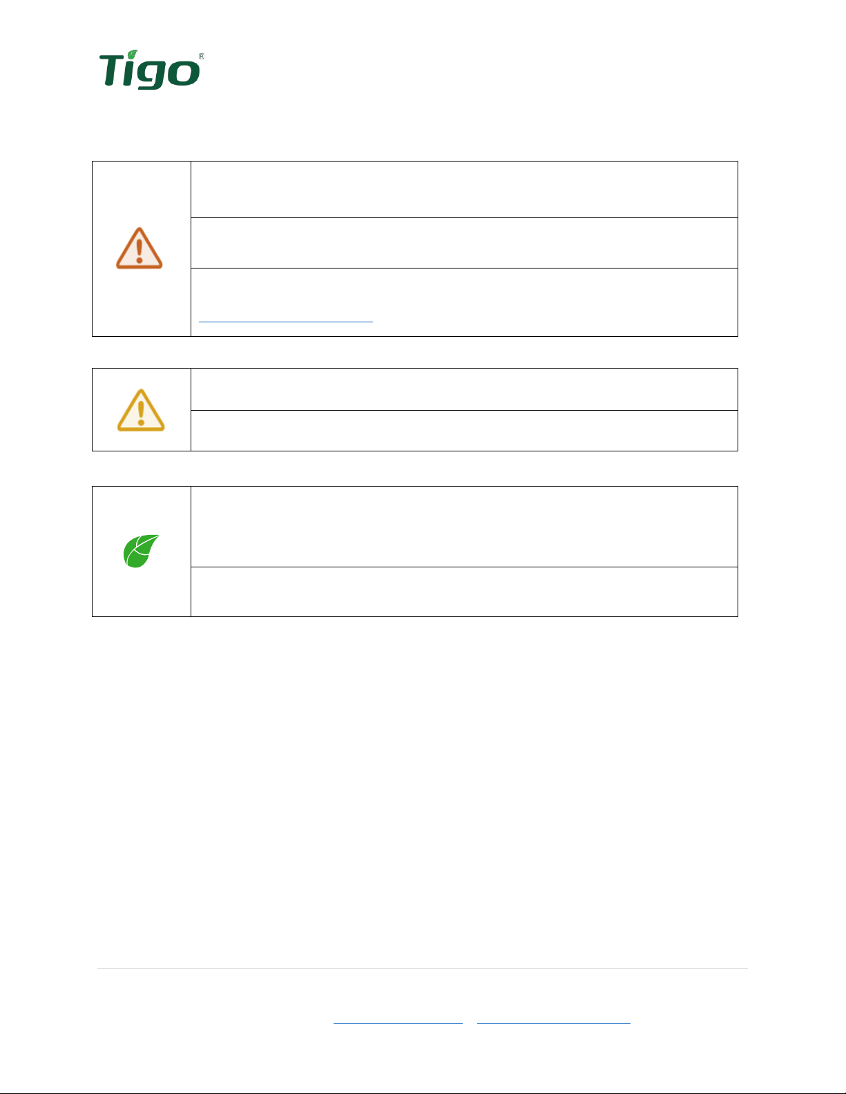
Safety Symbols
The following safety symbols are used in this Installation and Operations manual. Please review
these symbols and their meanings before installing or operating the system.
Symbol
Explanation
WARNING indicates a hazardous situation which, if not avoided, could
result in serious injury or loss of life.
AVERTISSEMENT indique une situation dangereuse qui, si elle n'est
pas évitée, pourrait entraîner la mort ou des blessures graves.
CAUTION indicates a hazardous situation which, if not avoided, could
result in minor or moderate injury and damage to the product.
ATTENTION indique une situation dangereuse qui, si elle n'est pas
évitée, pourrait entraîner des blessures mineures ou modérées.
NOTE is used to address additional information about the section’s
subject matter.
AVIS est utilisé pour traiter des pratiques non liées aux blessures
corporelles.
On the battery enclosure:
Symbol
Explanation
Risk of electrical shock
Risque d'électrocution
Risk of burn injuries
Risque de brûlures
Observe the operating instructions
Respectez les instructions de service
6 | Page
Tigo Energy, Inc. | www.tigoenergy.com | support@tigoenergy.com
Safety Information
Save these instructions.
Warning!
Read all instructions in this manual to reduce the risk of injury, damage, and
loss of life.
The equipment detailed in this document is to be installed and maintained by
qualified personnel only.
This product could expose the user to chemicals known to the State of
California to cause cancer. For more information refer to
www.P65Warnings.ca.gov.
Caution!
This product must operate within the technical specifications of the datasheet.
Damage caused by failure to follow the contents of the EI Battery Storage
Installation & Operation Manual is not covered by the warranty.
Note
The battery enclosure is NEMA 4 rated. Unused conduit openings must be
properly sealed and all connecting conduit requires the use of appropriate
fittings for the application.
Use only copper conductors, solid or stranded. Never use fine stranded
conductors. All conductors must have a minimum temperature rating of 75°C.

7 | Page
Tigo Energy, Inc. | www.tigoenergy.com | support@tigoenergy.com
EI Residential Solution Overview
The Tigo Energy Intelligence (EI) Battery provides energy resilience in the event of a grid
outage and optimizes energy consumption based on rate plans for today’s home energy needs.
The Tigo EI Battery is the energy storage component of Tigo’s Energy Intelligence Solution.
Each enclosure contains three battery modules for a total capacity of 9.9kWh.
The Energy Intelligence Residential Solution
The EI Residential Solution includes the following components:
1. EI Inverter – The TSI-7.6K-US and TSI-11.4K-US inverters may be installed as grid-
tied only or as an energy storage system when paired with the EI Battery. The inverter
converts the PV array’s DC energy to AC for use in the building and when paired with an
EI Battery, acts as the battery management unit.
2. TS4 – Tigo’s MLPE, the TS4-A-F provides module-level rapid shutdown. The TS4-A-O
provides module-level monitoring, rapid shutdown, and best-in-class module-level
optimization with Tigo’s patented Predictive IV.
3. EI Battery (optional) – The LFP battery is designed for use specifically with the EI
Inverter. Up to four battery enclosures may be installed with the EI Inverters.
4. EI ATS (required when batteries are used) – The EI ATS is an automatic transfer switch
that switches the home loads from grid + Solar/battery usage to solar/battery usage
only when the grid goes down. This is a required component of any energy storage
system when connected to the utility grid as it prevents the potential for dangerous
backfeed on the utility’s conductors.
5. Energy Meter – (optional / required when batteries are used) – The energy meter
monitors the import and export of energy into the home’s electrical system. This allows
the inverter to determine when and how much energy is required from the battery to
serve connected loads.
6. Energy Intelligence – Accessible through the web or mobile app, the EI Platform
provides visibility into system and module performance. The EI mobile app is also used
for commissioning the EI Residential Solution.
Figure 1 EI System Diagram
2
1
3
4
5
6

8 | Page
Tigo Energy, Inc. | www.tigoenergy.com | support@tigoenergy.com
Transportation and Storage
When possible, transport the battery enclosure and battery modules in the original packaging,
facing up and do not expose to inclement weather or unnecessary shocks and vibrations. If the
original packaging cannot be used, a box of similar size, without damage, and can
accommodate the weight of the battery enclosure and/or battery module may be used. Take
precautions to ensure the packaging is fully closed and reasonably weather tight.
To store the battery enclosure, select a dry environment with ambient temperatures of -4°F to
113°F (-20°C – 45°C).
Understanding this Document
This manual includes installation references to four separate components of the complete
Energy Intelligence Residential Solution: inverter, battery, ATS and energy meter. Each of these
components are required for the proper operation of the EI Battery.
Installation of the equipment can take place concurrently, although the EI Inverter is the hub of
all equipment in this system. Where a workstream can split off from the main efforts of battery
installation a QR code will be provided directing to the appropriate product’s documentation.

9 | Page
Tigo Energy, Inc. | www.tigoenergy.com | support@tigoenergy.com
Pre-Installation
When receiving delivery of the EI Battery, examine the packaging for damage. If the packaging
appears to have damage through the box and into the contents, refuse delivery and notify the
vendor immediately. If damage appears external only, open the box and inspect for any product
damage and/or missing parts.
EI Battery Package Contents
Open the package and inspect the contents. The following components should be included. If
anything is missing, please contact the vendor immediately.
Figure 2 Package contents
Table 1 Package list
Item
Description
Quantity
A
Battery Enclosure
1
B
Quick Start Guide
1
C
Sleeve anchor
2
D
Wire ferrule
4
E
Safety-lock screws
6
Note:
The battery modules are shipped separately from the EI Battery enclosure. Three
battery modules are installed in each EI Battery enclosure.
A
B
C D E

10 | Page
Tigo Energy, Inc. | www.tigoenergy.com | support@tigoenergy.com
Tools & Items Needed for Installation
Table 2 Required Tools
Item
Needed for:
#2 Phillips screwdriver
Removing/replacing covers
1/8” flathead screwdriver
Terminating conductors
Pencil
Marking drill holes
Level
Mounting the equipment
Drill & 8mm drill bit*
Drilling pilot holes for mounting. *Bit size will depend on
the mounting surface material and anchor sizes required.
EI Battery Overview
Left side
Front
Right side
Back
Figure 3 Battery Enclosure Overview
1) Handle
2) Battery enclosure
3) Base
4) Disconnect switch
5) DC knockout
6) Power button
7) Communications knockout
8) Inverter connection
wire box
9) Front cover
10) LED indicator
11) Base front cover
12) Battery expansion wire box
13) GEC/bonding terminal
14) Mounting tabs
15) Heat sink
11 | Page
Tigo Energy, Inc. | www.tigoenergy.com | support@tigoenergy.com
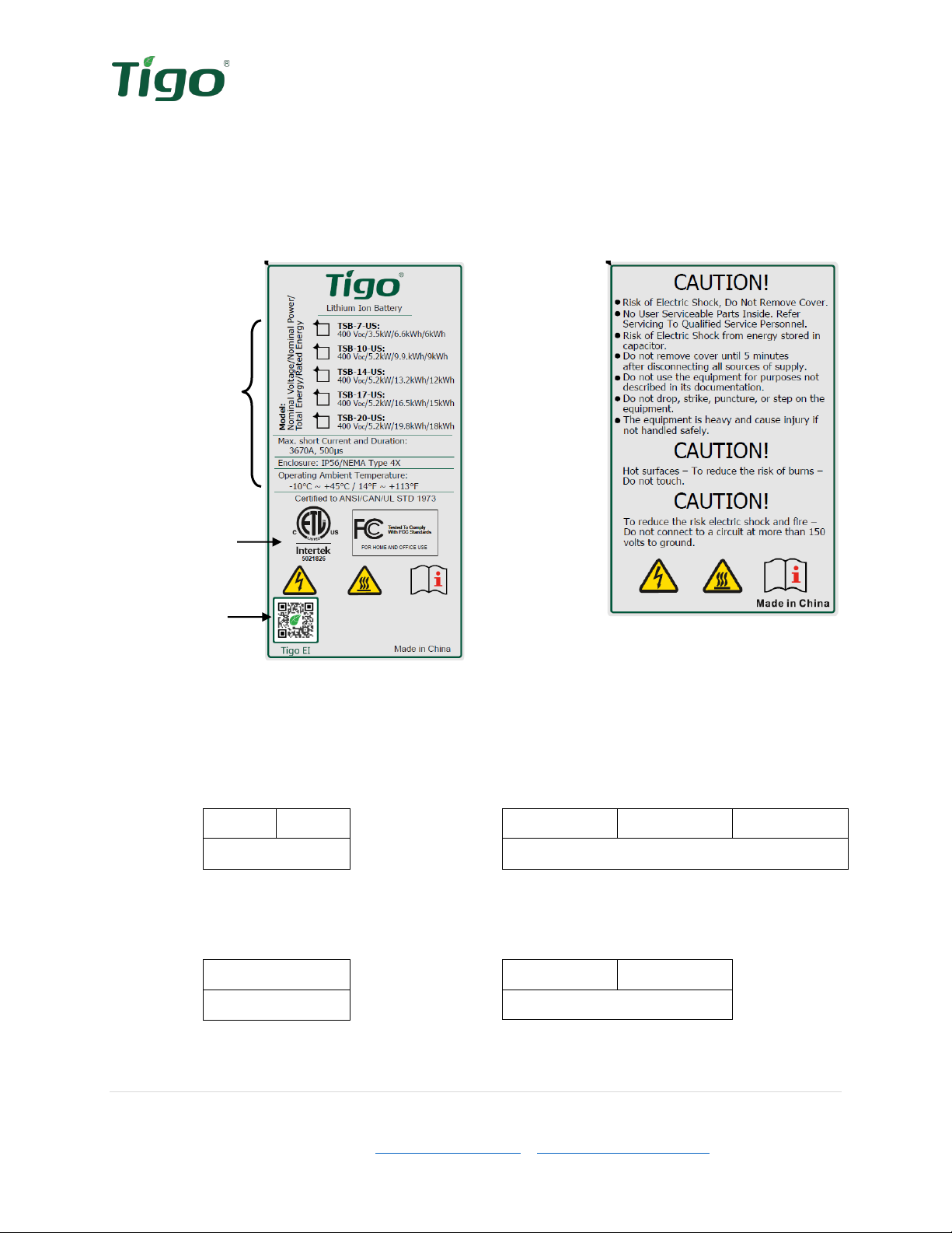
EI Battery Labels
EI Battery labels provide the technical specifications of the product as well as important safety
information. Additional information is available on these and other labels which will help with
the commissioning and installation of the EI Battery.
Battery Specifications
Safety Labels
Model Number &
Specifications
Figure 4 Specifications label
Figure 5 Safety label
Certifications
Tigo EI App
The battery enclosure has a wire box door on each side. The
inverter connection wire box
(8)
includes two labels specifying the battery output terminals for connection to the inverter and
the communications ports.
+
-
BAT
Figure 6 BAT-INV label
INV
Link in
Link out
COM
Figure 7 BAT COM label
The
battery expansion wire box
(12) includes two labels specifying the battery expansion
terminals for connection to additional EI Batteries and a communications port.
CAN
COM
Figure 8 CAN/COM label
+
-
BAT-Expansion
Figure 9 BAT-Expansion label
12 | Page
Tigo Energy, Inc. | www.tigoenergy.com | support@tigoenergy.com
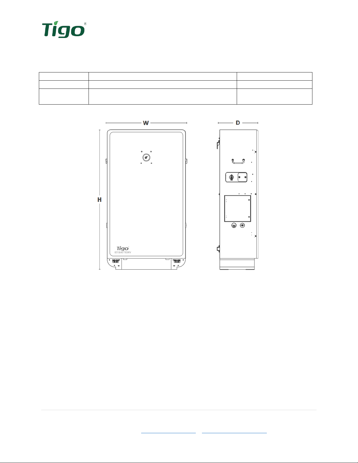
EI Battery Weight and Dimensions
Table 3 Weight and Dimensions
Model
Dimensions (W x D x H)
Weight
TSB-10-US
25.6 x 12.6 x 45.7in (650 x 320 x 1160mm)
308.6lbs (140kg)
TSB-20-US
2pcs: 25.6 x 12.6 x 45.7in (650 x 320 x 1160mm)
each
2pcs: 308.6lbs (140kg)
each
Figure 8 Battery enclosure dimensions
Selecting the Installation Location
The EI Battery enclosure’s
Inverter connection wire box
(8) is on the left. Consider the conduit
path between the left side of the EI Battery and the EI Inverter when choosing the installation
location.
When multiple EI Batteries are being installed, consider the conduit path between the right
sides of any two battery enclosures. The
Battery expansion wire box
(12) is located on the
right side and the expansion connections occur between these wire boxes.
13 | Page
Tigo Energy, Inc. | www.tigoenergy.com | support@tigoenergy.com
Installation requirements
The battery installation must comply with the following requirements.
▪Select a wall or solid vertical surface that can support the EI Battery.
▪Select an installation location in which the LED display on the front cover will be easily
viewed.
▪Select a well-ventilated location sheltered from direct sunlight and rain.
▪Do not install in cabinets; good ventilation ensures the heat will adequately escape.
oThe ambient temperature should be below 40°C for optimal operation.
▪Do not install the battery enclosure on structures constructed of highly flammable
materials.
▪The humidity at the installation location must be 0-100% without condensation.
▪The installation location shall always be accessible.
▪Mount the battery enclosure vertically. Do not install horizontally, tilting forward,
sideways or facing upside down.
▪Do not install and operate the battery on or near easily flammable material.
▪Ensure the EI Battery is out of reach of children.
▪Do not cover or place items on the battery enclosure.
▪Install in a location away from any antennas or any other sources of strong
electromechanical interference.
Note:
If installing multiple battery enclosures, the battery expansion cables should not
exceed a length of 6ft-7in. Space enclosures accordingly.
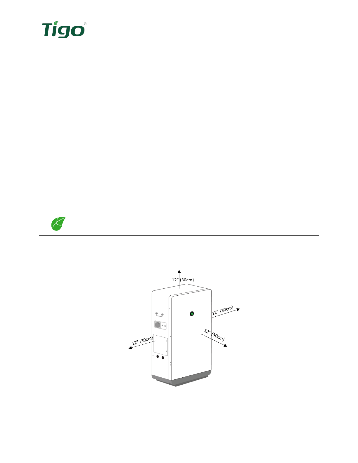
The minimum clearances shown below must be observed.
Figure 9 Clearances

14 | Page
Tigo Energy, Inc. | www.tigoenergy.com | support@tigoenergy.com
Installation
Caution
For personal safety always wear appropriate PPE and use all safety precautions
suitable for the working environment, including the use of insulated tools.
Note:
All electrical installations must be completed in accordance with all local
electrical codes and the National Electric Code, NFPA 70 (NEC). For installation
in Canada the installations must be completed in accordance with applicable
Canadian standards. Before connecting the inverter to the power distribution
grid, contact your local electric utility company. These connections may only be
made by qualified personnel.
Mounting the EI Battery
Tools needed: Electric drill, 8mm bit hammer/mallet, level, pencil, socket wrench
Accessory parts needed: Sleeve anchors (C)
Warning!
Before drilling into the wall, inspect for existing electrical or plumbing installations
to avoid electric shock or other injuries.
Note
The instructions below are for securing the enclosure to drywall. If another surface
is used, use the appropriate hardware to securely mount the battery enclosure.
1) Before positioning the EI Battery in place, identify the
mounting tabs
(14) on the back of the enclosure. Place
the EI Battery and rotate the mounting tabs 90º to the
outside.
2) Mark holes through the mounting tabs for
drilling. Drill 2in (5cm) deep holes with an
8mm bit.
Figure 10
Mounting tabs
Figure 11
Mounting
preparation

15 | Page
Tigo Energy, Inc. | www.tigoenergy.com | support@tigoenergy.com
3) Insert sleeve anchors in the pilot holes and assemble the
anchor. Secure bolt and washers against the mounting tabs
to secure to the wall.
Removing the front cover
Tools needed: #2 Philips head screwdriver
1) Remove the lower
base plate
(11) and 6
screws (3 from each side) securing the
front
cover
(9). Unlatch the two front cover locks
from the bottom, as shown.
2) Tilt cover up and CAREFULLY swing the front cover to the left, using caution to not pull
ground or display wires.
CAUTION!
The front cover has a grounding wire and
display cable attached to the interior. Use
caution and detach wires before carefully
attempting to remove the cover.
Figure 12 Securing the EI Battery
Figure 13 Base plate removal
Figure 14 Front cover removal

16 | Page
Tigo Energy, Inc. | www.tigoenergy.com | support@tigoenergy.com
3) Unscrew ground conductor and unplug the
display cable then set front cover aside.
Battery module installation
Accessory parts needed: Battery modules (shipped separately, 3 per enclosure)
Unbox the battery modules to prepare for installation. The modules
are shipped with enough charge to allow dark start. The battery
module’s power terminals face the right side of the EI Battery
enclosure.
The battery cables are pre-installed and labeled inside the
enclosure. These cables are tied inside the enclosure. These cable
ties will need to be cut in order to make the required connections.
WARNING!
Danger to life from electric shock due to high voltages. High voltages
are present in the DC cables and during the operation of the system.
Do not install and operate the EI Battery on or near easily flammable
material.
CAUTION!
Risk of burns due to hot surfaces. The surface of the battery enclosure
can become very hot. During operation do not touch any portion other
than the wire box compartment. Mount the EI Battery such that it
cannot be inadvertently touched.
CAUTION!
Only make the internal battery connections when the battery EI
Residential Solution will be ready to be turned on and begin charging
the batteries. Never leave batteries connected without the ability to
charge from the grid or PV power.
Figure 15 Display cable and ground
connection
Figure 16 Battery modules
17 | Page
Tigo Energy, Inc. | www.tigoenergy.com | support@tigoenergy.com
Place battery module in the enclosure then slide the
brackets inward on each side of the battery and
tighten the wingnuts to secure.
Wiring the battery modules (Battery enclosure 1)
CAUTION!
Do not reverse the positive and negative of the battery input terminals.
Note:
The battery conductors and communications cables are labeled and located
inside the enclosure. Carefully cut cable ties and connect as shown. When
properly installed a “click” will be heard.
Three types of cables are located inside the EI Battery enclosure:
•The PCS communication cable is used to connect the batteries to the Battery
Management System (BMS) inside the EI Battery enclosure. Only one battery module 1
(upper battery) is connected directly to the BMS in a single EI Battery installation.
•The battery modules are connected in series by the Link-In and Link-Out
communications cables.
•The battery modules are wired together for power using the BAT+ and BAT-
conductors.
Note:
The battery module serial numbers will be needed later during the commissioning
and warranty completion. The serial is provided on the battery module as well as
its box. Note which battery is installed in each position on the respective box.
Figure 17 Mounting the
battery modules

18 | Page
Tigo Energy, Inc. | www.tigoenergy.com | support@tigoenergy.com
Lower
battery
Upper battery
1) Locate the cables labeled for the upper battery module and cut
cable ties to free the cables.
2) Connect the Upper Bat PCS cable to the battery terminal labeled
PCS.
3) Connect the upper BAT link-out cable to the battery port
labeled link-out.
4) Connect the upper BAT + plug to the red battery terminal
labeled +.
5) Connect the upper BAT - plug to the black battery terminal
labeled -.
Figure 19 Upper battery connections
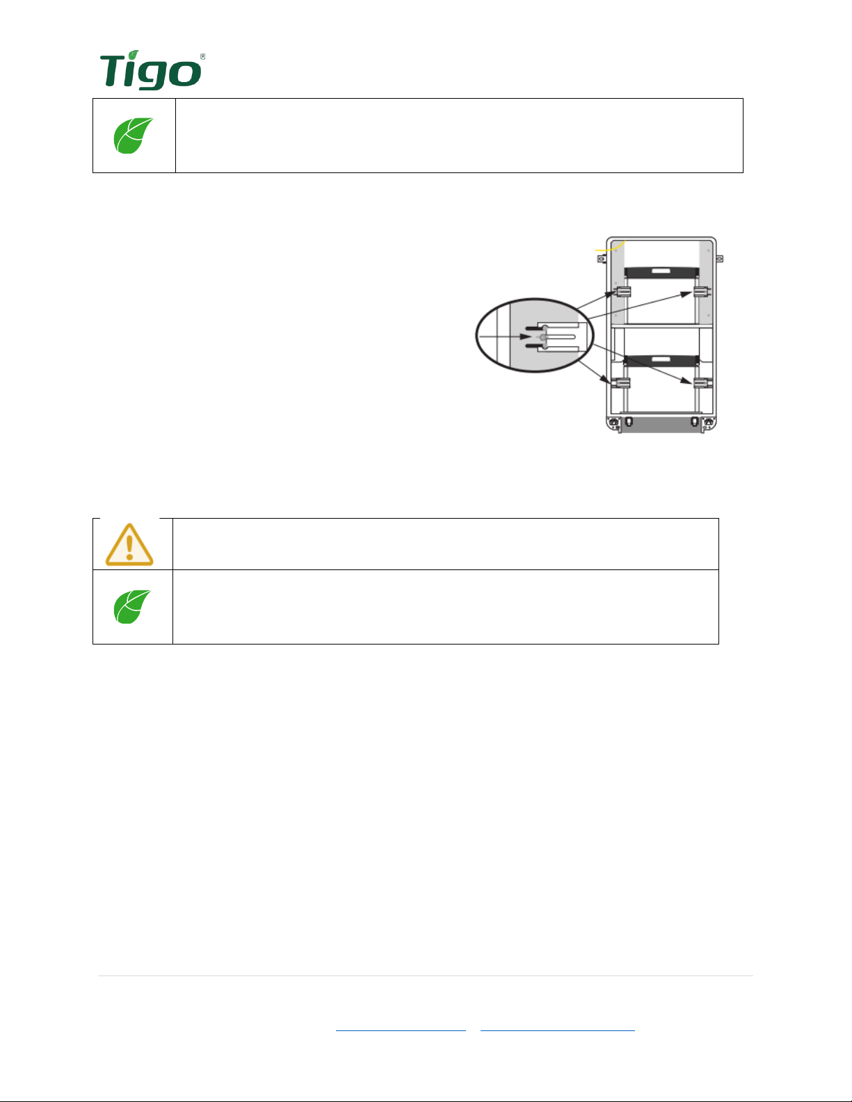
Lower batteries
Note:
IF INSTALLING ONLY ONE EI BATTERY ENCLOSURE, a terminating cap is required in
the CAN/COM port in the right-side
battery expansion wire box
(12). Do not
remove this cap.
Inner battery
1) Locate the cables labeled for the lower battery modules and cut
cable ties to free the cables.
2) Connect provided lower inner BAT link-out cable (loose cable) to
the lower inner battery terminal labeled link-out.
3) Connect the opposite end of the lower inner BAT link-out cable
from step 2 to the link-in terminal on the lower outer battery.
4) Connect the lower inner BAT link-in cable to the lower inner
battery link-in terminal.
5) Connect the lower inner BAT + plug to the lower inner battery red
terminal labeled +.
6) Connect the lower inner BAT - plug to the lower inner battery
Figure 18 Upper
battery module
Figure 20 Lower
battery modules

19 | Page
Tigo Energy, Inc. | www.tigoenergy.com | support@tigoenergy.com
black terminal labeled -.
Outer battery
7) Connect the lower outer BAT + plug to the lower outer battery red terminal
labeled +.
8) Connect the lower outer BAT - plug to the lower outer battery black terminal
labeled -.
9) Connect the lower outer BAT link-out cable to the link-out terminal on the lower
outer battery.
Figure 21 Lower battery connections
10) After all three batteries have been installed and connected, the
front cover
(9) can be
replaced by following the steps to remove the cover in reverse order. Remember to
plug in the display cable and reconnect the EGC. The 6 front cover screws should
be torqued to 1Nm.

20 | Page
Tigo Energy, Inc. | www.tigoenergy.com | support@tigoenergy.com
Wiring the battery modules (Battery enclosure 2)
If installing a second EI Battery enclosure complete the power, Link-In and Link-Out
connections as described in the previous section.
EI Battery enclosure 1
Remove the terminating cap from the CAN/COM terminal in the
Battery expansion wire box
(12) and insert it in the Link-in terminal of battery module 1 (upper module/enclosure 1).
EI Battery enclosure 2
The terminating cap is inserted in the CAN/COM terminal in the
Battery expansion wire box
(12). Do not remove this cap.
In the next section,
Wiring the EI Battery – Battery expansion
, a communication
cable is routed between the two enclosures. At the second enclosure this cable will
terminate at the Link-in terminal of battery module 4 (upper module/enclosure 2).
Figure 22 Battery module expansion wiring diagram
BAT 1
Upper
Enclosure 1 Enclosure 2
BAT 2
Lower Inner
BAT 3
Lower Outer
Bottom
Top Upper BAT Link-out
Lower inner BAT Link-in
Lower outer BAT Link-out
Right
Side
Wire
Box
Right
Side
Wire
Box
Upper BAT Link-out
Lower inner BAT Link-in
Lower outer BAT Link-out
Terminating
Cap
Terminating
Cap
BAT 4
Upper
BAT 5
Lower Inner
BAT 6
Lower Outer
Bottom
Top
Lower inner BAT Link-out
Lower outer BAT Link-in
This manual suits for next models
1
Table of contents
Popular Batteries Pack manuals by other brands


Kicker
Kicker iZKBP350 owner's manual

SunStone Power
SunStone Power SLPO12-200N user manual

Odyssey
Odyssey Extreme Series Technical manual

Mid-Continent Instrument
Mid-Continent Instrument True Blue Power TB60 Series Installation manual and operating instructions

Glentronics
Glentronics PHCC-1000 Pro Series Additional instructions

Panasonic
Panasonic CF-VZSU53AW Operation manual