Publication No: US-ODY-TM-AA September 2016
www.odysseybattery.com 9
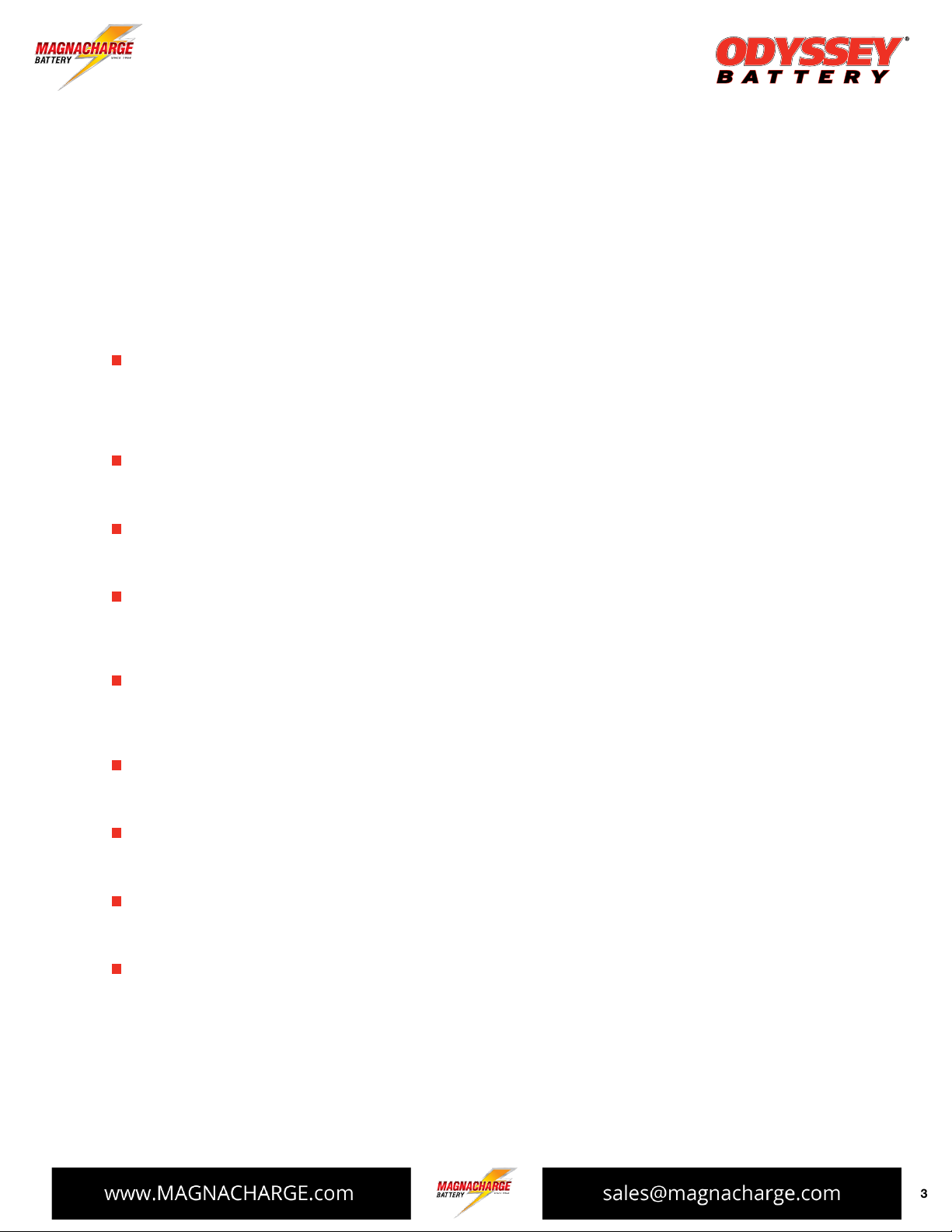
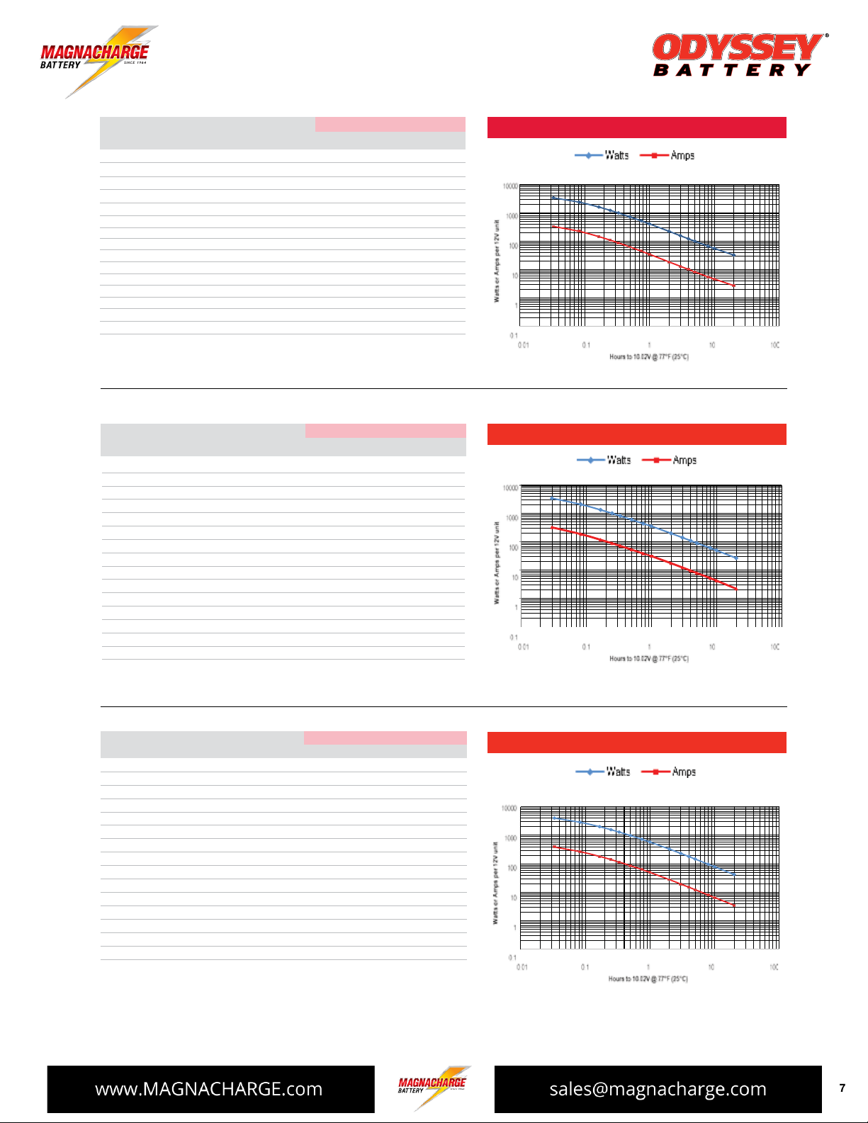
Time Watts Amps Capacity Energy ENERGY AND POWER DENSITIES
(W) (A) (Ah) (Wh) W/liter Wh/liter W/kg Wh/kg
2 min 5234 497.7 14.9 157.0 551.5 16.5 233.7 7.0
5 min 3367 306.4 25.5 280.6 354.8 29.6 150.3 12.5
10 min 2194 194.4 32.4 365.7 231.2 38.5 98.0 16.3
15 min 1655 144.7 36.2 413.8 174.4 43.6 73.9 18.5
20 min 1339 116.0 38.7 446.3 141.1 47.0 59.8 19.9
30 min 978 83.9 41.9 489.1 103.1 51.5 43.7 21.8
45 min 704 59.9 44.9 528.1 74.2 55.6 31.4 23.6
1 hr 565 47.8 47.8 565.4 59.6 59.6 25.2 25.2
2 hr 311 26.0 52.0 621.2 32.7 65.5 13.9 27.7
3 hr 217 18.1 54.4 651.2 22.9 68.6 9.7 29.1
4 hr 168 14.0 56.0 672.2 17.7 70.8 7.5 30.0
5 hr 138 11.5 57.4 688.8 14.5 72.6 6.2 30.8
8 hr 93 7.7 61.8 741.7 9.8 78.2 4.1 33.1
10 hr 76 6.3 63.5 762.1 8.0 80.3 3.4 34.0
20 hr 42 3.5 70.3 840.2 4.4 88.5 1.9 37.5
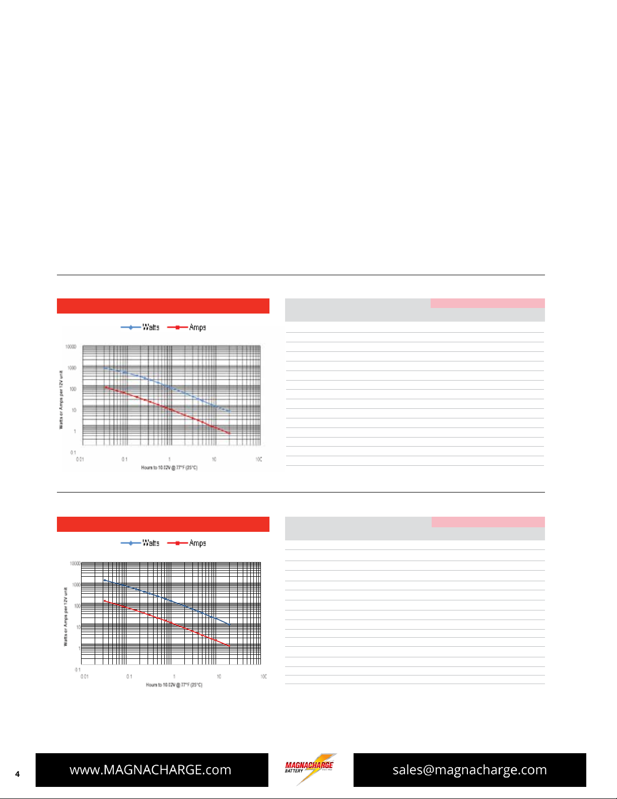
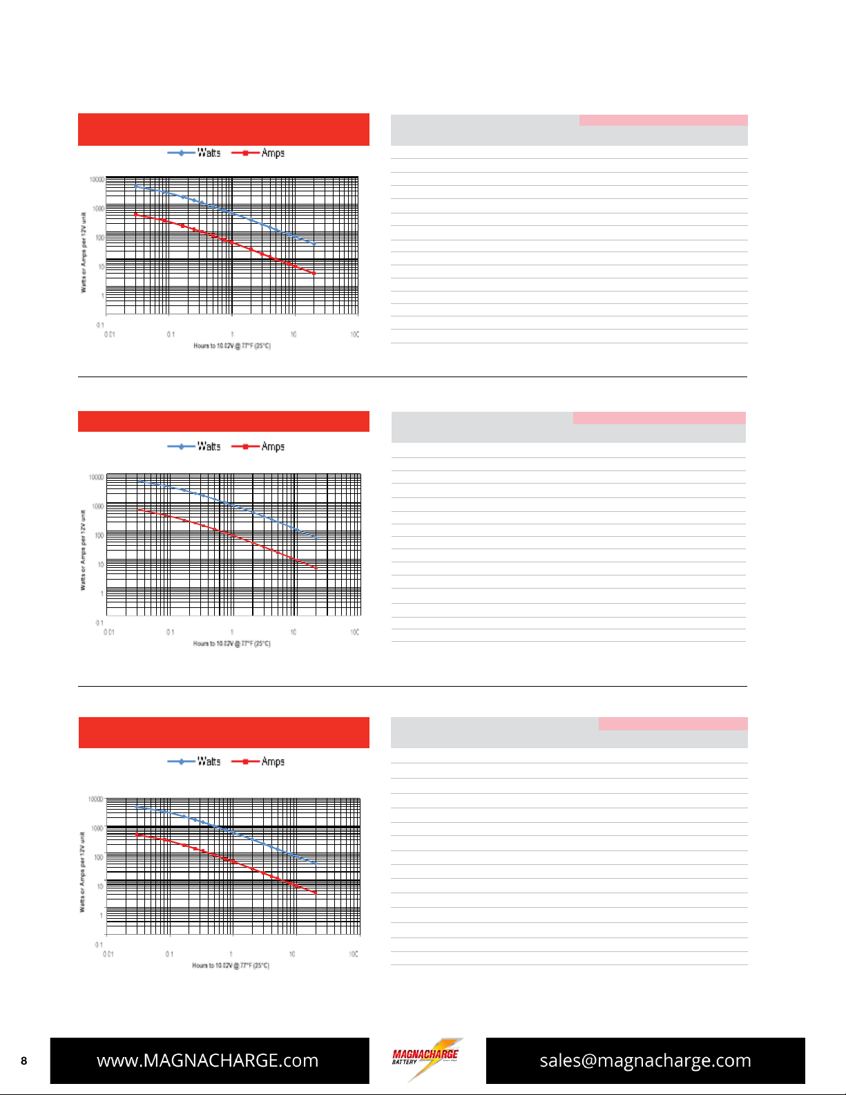
34-PC1500, 34R-PC1500, 34M-PC1500, 34/78-PC1500 and
78-PC1500 performance data at 77°F, per 12V module
Time Watts Amps Capacity Energy ENERGY AND POWER DENSITIES
(W) (A) (Ah) (Wh) W/liter Wh/liter W/kg Wh/kg
2 min 5146 490.0 14.7 154.4 467.4 14.0 186.4 5.6
5 min 3394 309.8 25.8 282.8 308.2 25.7 123.0 10.2
10 min 2255 200.5 33.4 375.8 204.8 34.1 81.7 13.6
15 min 1720 151.0 37.7 429.9 156.2 39.0 62.3 15.6
20 min 1401 122.0 407 467.1 127.3 42.4 508 16.9
30 min 1034 89.1 44.5 516.8 93.9 46.9 37.4 18.7
45 min 750 64.1 48.1 562.6 68.1 51.1 27.2 20.4
1 hr 605 51.4 51.4 605.3 55.0 55.0 21.9 21.9
2 hr 335 28.2 56.4 670.5 30.5 60.9 12.1 24.3
3 hr 235 19.7 59.0 704.0 21.3 63.9 8.5 25.5
4 hr 182 15.2 60.8 726.5 16.5 66.0 6.6 26.3
5 hr 149 12.4 62.1 743.5 13.5 67.5 5.4 26.9
8 hr 100 8.3 66.4 796.1 9.0 72.3 3.6 28.8
10 hr 8.1 6.8 68.0 814.4 7.4 74.0 3.0 29.5
20 hr 44 3.7 73.6 879.7 4.0 79.9 1.6 31.9
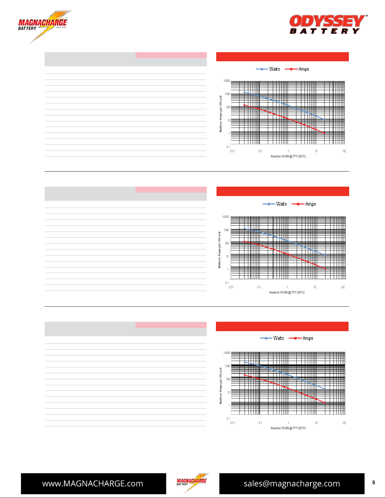
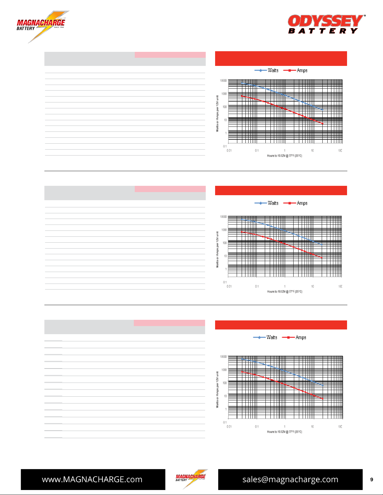
PC1700 performance data at 77°F, per 12V module
ENERGY AND POWER DENSITIES
Time Watts Amps Capacity Energy
(W) (A) (Ah) (Wh) W/litre Wh/litre W/kg Wh/kg
65-PC1750 performance data at 77°F, per 12V module
2 min 5741 544.8 16.3 172.2 549.4 16.5 218.3 6.5
5 min 3551 323.3 26.9 295.9 339.8 28.3 135.0 11.3
10 min 2297 203.7 33.9 382.8 219.8 36.6 87.3 14.6
15 min 1736 151.9 38.0 433.9 166.1 41.5 66.0 16.5
20 min 1409 122.3 40.8 469.6 134.8 44.9 53.6 17.9
30 min 1037 89.1 44.5 518.3 99.2 49.6 39.4 19.7
45 min 753 64.1 48.1 564.4 72.0 54.0 28.6 21.5
1 hr 608 51.5 51.5 608.1 58.2 58.2 23.1 23.1
2 hr 339 28.4 56.9 677.7 32.4 64.8 12.9 25.8
3 hr 238 19.9 59.8 714.3 22.8 68.4 9.1 27.2
4 hr 185 15.4 61.8 738.9 17.7 70.7 7.0 28.1
5 hr 151 12.7 63.3 757.4 14.5 72.5 5.8 28.8
8 hr 102 8.5 68.0 812.1 9.7 77.7 3.9 20.9
10 hr 83 7.0 69.6 830.5 7.9 79.5 3.2 31.6
20 hr 45 3.8 75.2 890.5 4.3 85.2 1.7 33.9