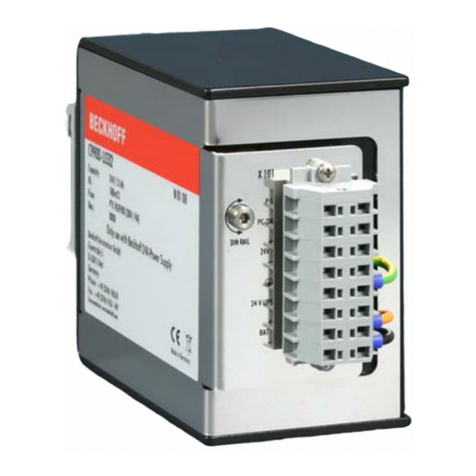
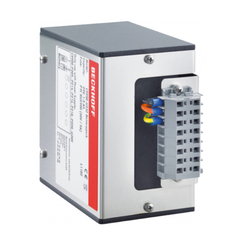
Beckhoff CX2900-0192 User manual

Manual | EN
CX2900-0192
Battery pack for CX2100-0914
2/10/2021 | Version: 1.4


Table of contents
CX2900-0192 3Version: 1.4
Table of contents
1 Notes on the documentation ....................................................................................................................5
1.1 Explanation of symbols and font conventions ...................................................................................6
1.2 Documentation issue status ..............................................................................................................8
1.3 Related documents............................................................................................................................8
2 Safety..........................................................................................................................................................9
2.1 Intended use......................................................................................................................................9
2.2 Staff qualification ...............................................................................................................................9
2.3 Safety instructions ...........................................................................................................................10
3 Transport and storage.............................................................................................................................11
3.1 Transport .........................................................................................................................................11
3.2 Storage ............................................................................................................................................12
4 Product overview.....................................................................................................................................13
4.1 Composition of the battery pack ......................................................................................................13
4.2 Name plate ......................................................................................................................................14
4.3 Connections.....................................................................................................................................15
4.3.1 X101 Power Supply ......................................................................................................... 15
4.3.2 X102 connection (RJ45) .................................................................................................. 15
5 Commissioning........................................................................................................................................16
5.1 Mounting..........................................................................................................................................16
5.1.1 Insert fuse ........................................................................................................................ 16
5.1.2 Installation on the mounting rail ....................................................................................... 17
5.2 Power supply with CX2100-0914 power supply unit .......................................................................19
5.2.1 Connect Embedded PC ................................................................................................... 19
5.2.2 Observe the UL requirements.......................................................................................... 21
5.2.3 Connect battery pack....................................................................................................... 22
5.2.4 Supplying external devices. ............................................................................................. 24
6 Care and maintenance ............................................................................................................................26
6.1 Care.................................................................................................................................................26
6.2 Maintenance ....................................................................................................................................26
7 Decommissioning....................................................................................................................................27
7.1 Disassembly and disposal ...............................................................................................................27
8 Error handling and diagnostics..............................................................................................................28
8.1 Battery pack LEDs...........................................................................................................................28
8.2 Faults...............................................................................................................................................29
9 Technical data..........................................................................................................................................30
10 Appendix ..................................................................................................................................................32
10.1 Accessories .....................................................................................................................................32
10.2 Certifications....................................................................................................................................33
10.3 Support and Service ........................................................................................................................34

Table of contents
CX2900-01924 Version: 1.4

Notes on the documentation
CX2900-0192 5Version: 1.4
1 Notes on the documentation
This description is only intended for the use of trained specialists in control and automation engineering who
are familiar with applicable national standards.
It is essential that the documentation and the following notes and explanations are followed when installing
and commissioning the components.
It is the duty of the technical personnel to use the documentation published at the respective time of each
installation and commissioning.
The responsible staff must ensure that the application or use of the products described satisfy all the
requirements for safety, including all the relevant laws, regulations, guidelines and standards.
Disclaimer
The documentation has been prepared with care. The products described are, however, constantly under
development.
We reserve the right to revise and change the documentation at any time and without prior announcement.
No claims for the modification of products that have already been supplied may be made on the basis of the
data, diagrams and descriptions in this documentation.
Trademarks
Beckhoff®, TwinCAT®, EtherCAT®, EtherCAT G®, EtherCAT G10®, EtherCAT P®, Safety over EtherCAT®,
TwinSAFE®, XFC®, XTS® and XPlanar® are registered trademarks of and licensed by Beckhoff Automation
GmbH.
Other designations used in this publication may be trademarks whose use by third parties for their own
purposes could violate the rights of the owners.
Patent Pending
The EtherCAT Technology is covered, including but not limited to the following patent applications and
patents:
EP1590927, EP1789857, EP1456722, EP2137893, DE102015105702
with corresponding applications or registrations in various other countries.
EtherCAT® is a registered trademark and patented technology, licensed by Beckhoff Automation GmbH,
Germany
Copyright
© Beckhoff Automation GmbH & Co. KG, Germany.
The reproduction, distribution and utilization of this document as well as the communication of its contents to
others without express authorization are prohibited.
Offenders will be held liable for the payment of damages. All rights reserved in the event of the grant of a
patent, utility model or design.

Notes on the documentation
CX2900-01926 Version: 1.4
1.1 Explanation of symbols and font conventions
In this documentation the following symbols are used with an accompanying warning or note. The warnings
must be read carefully and strictly observed.
Symbols that warn of personal injury:
DANGER
Serious risk of injury
Be sure to observe this warning. Non-compliance will lead to serious injury or death.
WARNING
Risk of injury
It is essential to observe this warning. Non-compliance can lead to serious injury or death.
CAUTION
Personal injuries
It is essential to observe this warning. Non-compliance can lead to minor or slight injury.
Symbols that warn of damage to property or equipment:
NOTE
Damage to the devices or environment
It is essential to observe this warning. Non-compliance can lead to damage to property or equipment or en-
vironmental damage.
Symbols indicating further information or tips:
Tip or pointer
This symbol indicates information that contributes to better understanding.

Notes on the documentation
CX2900-0192 7Version: 1.4
Font conventions
The following table shows the font conventions used in this documentation. They also serve as a guide,
since the font is consistently applied in the document.
Font / label Meaning
Internal reference [}6] Internal references to sections, for example.
External reference External references, e.g. to a website or other documentation.
italics File names, e.g. Setup.exe, and path names, e.g.
C:\Windows\System32\... are shown in italics.
Start > Programs A “greater than” sign between two words indicates selection of a
menu item from a menu or toolbar, e.g.
Start > Programs.
Menu Menu items are shown in bold, e.g.
In the File menu, click on Print.
Password Names of input or selection fields are displayed in bold, e.g.
Enter your password in the Password field.
[Key] Keyboard keys are shown in square brackets and bold, e.g.
[F1].
Button Buttons are shown in bold, e.g.
Click Continue.
“Inputs” and “Values” Input or selection values are shown in quotes, e.g.
In the Resolution menu, enter the value “1280x800”.
Programmcode Program code is indicated by a different font and highlighted in color,
e.g.
VAR_OUTPUT
BUSY :BOOL;
ERR :BOOL;
ERRID :UDINT;
END_VAR

Notes on the documentation
CX2900-01928 Version: 1.4
1.2 Documentation issue status
Version Modifications
1.0 First version
1.1 Technical data revised
1.2 Chapter “Care and maintenance” added.
Information about product safety label added, in
chapter “Safety instructions”
1.3 Chapter “power supply”, “product overview” and
“technical data” revised.
1.4 Chapter “Connect battery pack” revised.
1.3 Related documents
This documentation contains and describes material that is relevant for the battery pack. The battery pack is
part of a modular systems and belongs to the CX2000 Embedded PC series. Further information on the
devices of the CX2000 Embedded PC series can be found in the associated documentation. Read and
follow in particular the sections on safety in this documentation.
The following important documentation can be viewed at and downloaded from the Beckhoff website:
www.beckhoff.de
Document name
CX20x0 hardware description
CX2100-0914 power supply unit for CX20x0
Retaining the documentation
This documentation is part of the CX2900-0192 battery pack. Keep the documentation in the immediate
vicinity of the battery pack throughout its entire service life. Ensure that personnel have access to the
documentation at all times. Pass on the documentation to subsequent users, and in addition ensure that all
supplementary information is included in the documentation.

Safety
CX2900-0192 9Version: 1.4
2 Safety
To protect against injury and to prevent damage to equipment or property, it is necessary to carefully read
the safety guidelines and comply with them. This section contains a summary of the main safety
requirements and instructions. Warnings relating to specific action steps are included in the respective
sections.
Limitation of liability
All the components are supplied in particular hardware and software configurations appropriate for the
application. Unauthorized modifications and changes to the hardware or software configuration, which go
beyond the documented options, are prohibited and nullify the liability of Beckhoff Automation GmbH & Co.
KG.
In addition, the following actions are excluded from the liability of Beckhoff Automation GmbH & Co. KG:
• Failure to comply with this documentation.
• Improper use.
• Deployment of personnel without adequate training.
• Use of unauthorized replacement parts.
• Use of equipment that is not in sound condition.
2.1 Intended use
The battery pack is a charge store for the power supply unit CX2100-0914 and is only suitable for operation
with this power supply unit. The battery pack is intended for installation on a DIN rail.
In the event of a power failure the battery pack supplies the basic CPU module and further devices (e.g. a
Panel) via the CX2100-0914 power supply unit.
The battery pack is designed for a working environment that meets the requirements of protection class
IP20. This involves finger protection and protection against solid foreign objects up to 12.5 mm, but not
protection against water.
Ensure the battery pack is fully functional and replace it after five years.
Improper use
• Use the battery pack according to the technical data, otherwise electrolyte (acid) may escape and the
battery pack may become hot or even explode.
• The battery in the battery pack must not be removed and used outside the housing.
• Do not use the battery pack for more than 5 years.
2.2 Staff qualification
Using the Beckhoff software and hardware requires special qualifications. Personnel must have the following
minimum qualifications:
Beckhoff hardware
• All operations must be carried out by qualified personnel only, who have adequate knowledge in the
field of control and automation technology.
• The qualified personnel must be familiar with the current standards and guidelines for the devices and
the automation environment.
• All interventions require adequate knowledge of control programming.

Safety
CX2900-019210 Version: 1.4
2.3 Safety instructions
Follow the safety instructions for protection against injuries and prevention of damage to equipment or
property.
Mounting
• Never work on live equipment. Always switch off the power supply for the device before installation,
troubleshooting or maintenance. Protect the device against unintentional switching on.
• Avoid polarity reversal of the data and supply cables, as this may cause damage to the equipment.
• Observe the relevant accident prevention regulations for your machine (e.g. the BGV A 3, electrical
systems and equipment).
• Note the temperature limit values for operation. If the battery pack is operated outside these
temperature limits, it may leak electrolyte (acid), heat up or even explode.
• The space where the battery pack is located must have adequate ventilation. Follow the regulations of
VDE 0510 Part 2 / EN 50272-2 or corresponding national regulations for storage, installation and
operation.
The battery pack can release flammable gases, which may cause an explosion if it is located in an
enclosed, unventilated space.
• Do not store the battery pack in an airtight container or bag. The battery pack may release flammable
gases, which may explode if the battery pack is hermetically enclosed.
Contact with electrolyte (acid)
• Should you come in contact with electrolyte (acid), immediately rinse the affected body part with water.
Firefighting
Extinguish the battery pack with dry powder, halon or CO2.
• Do not use water, which could result in electrolyte (acid) splashing out.
• Disconnect the power supply.
• During firefighting wear self-contained respiratory protective equipment and protective clothing.
• Provide adequate ventilation after the battery pack has been extinguished.
Product safety label
The following product safety label is located on the right side of the battery pack.
CAUTION:
· Do not charge in a gas tight container.
· Do not short the battery terminals.
· Do not incinerate.
· Flush with water at once if contact
is made with electrolyte (Acid).

Transport and storage
CX2900-0192 11Version: 1.4
3 Transport and storage
3.1 Transport
NOTE
Short circuit due to moisture
Moisture can lead to short circuits. Moisture can form during transport in cold weather or in the event of
large temperature fluctuations.
Avoid moisture formation (condensation) in the device, and leave the device to adjust to room temperature
slowly. If condensation has occurred, wait at least 12 hours before switching on the device.
Transport
Despite the robust design of the unit, the components are sensitive to strong vibrations and impacts.
Therefore, during transport please protect your device from:
• mechanical stress and
• use the original packaging.
Dimensions and weight of the individual modules
Battery pack CX2900-0192 Power supply unit
CX2100-0914
Dimensions (W x H x D) 163 mm x 90 mm x 85 mm 84 mm x 100 mm x 91 mm
Weight approx. 2100 g approx. 695 g
Unpacking
1. Check the pack contents for visible transport damage and electrolyte (acid) leaks.
2. Do not discard the original packaging. Keep it for transporting the device in the future.
3. If you notice any shipping damage or inconsistencies between the contents and your order, you
should notify Beckhoff Service.

Transport and storage
CX2900-019212 Version: 1.4
3.2 Storage
WARNING
Fire and explosion hazard
The battery pack may release flammable gases, which may result in a fire or even an explosion.
Store the battery pack in a space with adequate ventilation, never in an airtight container or bag.
Observe the following storage conditions, in order to maintain the service life of the battery pack:
• Store the battery pack in discharged state.
• Remove the fuse from the battery pack.
• Store the battery pack at room temperature or below.
• Do not store the battery pack in a dusty environment, at high humidity or in location with strong
vibrations.
If the battery pack is stored for 3 months or more, it must be recharged at regular intervals.
Table1: Recharging intervals depending on the storage temperature.
Storage temperature Recharge after
Below 20 °C 12 months
20°C to 30°C 9 months
20°C to 40°C 6 months
Recharge the battery pack after 12 months at the latest. Avoid deep discharge of the battery pack.
Table2: Self-discharge behavior at 25°C.
Period Battery pack charge (%)
after 3 months 91% charge
after 6 months 82 % charge
after 12 months 64 % charge

Product overview
CX2900-0192 13Version: 1.4
4 Product overview
The battery pack contains a lead-gel battery. The battery pack is used as a UPS in conjunction with the
CX2100-0914 power supply unit. In the event of a power failure the battery pack supplies the basic CPU
module and further devices (e.g. a Panel) via the CX2100-0914 power supply unit.
The battery pack is connected to the power supply unit with two cables. A three-pole cable is used to
connect the power supply unit and the battery pack. The battery pack is also charged via the three-pole
cable.
The second connection (RJ45 patch cable) controls the charging/discharging behavior. It is a serial protocol,
not a network connection.
Operating times without power supply from the power supply unit (self-discharge).
With hardware version 1.0 the charged battery pack has the following operating times
• 4 – 6 weeks.
• 40 – 60 weeks, if the fuse was removed from the battery pack.
From hardware version 1.1 the charged battery pack has the following operating times
• 40 – 60 weeks.
4.1 Composition of the battery pack
1
2
7
3 4 65
Table3: Legend relating to the composition of the battery pack
No. Description
1 Name plate.
2 FUSE compartment for a 10 A fuse (FF).
3 Connection X101 for the power supply between the battery pack and the power supply unit
CX2100-0914.
4 RJ45 connection X102 for the data connection between the battery pack and the power
supply unit CX102-0914.
5 Operating button for the diagnostic LEDs.
6 Diagnostic LEDs indicate the charge state and the operational readiness.
7 Warning label with safety instructions.

Product overview
CX2900-019214 Version: 1.4
4.2 Name plate
A name plate can be found on the left-hand side of the battery pack housing.
Model
Serial No.
HW
Date
Only use with CX2100-0914
CX2900-0192
Made in Germany
Beckhoff Automation GmbH & Co. KG
Hülshorstweg 20, D-33415 Verl
Documentation: www.beckhoff.com
123
2.0
24.12.2015
1
2
4
3
Table4: Legend for the battery pack name plate.
No. Description
1 CE compliant.
2 Indicates that the battery pack should only be operated with the CX2900-0914 power
supply unit.
3 Information on:
• model,
• serial number,
• hardware version
• and date of manufacture.
4 Manufacturer information including address.

Product overview
CX2900-0192 15Version: 1.4
4.3 Connections
4.3.1 X101 Power Supply
X101
The CX2100-0914 power supply unit is connected to the X101 connector. The earth, -BAT and +BAT cables
are connected to the corresponding terminals on the power supply unit.
This connection is used to charge the battery pack and supply the CX system in the event of a power failure.
4.3.2 X102 connection (RJ45)
Confusion with the network connection
This connector is used for processing a serial protocol for communication between the power sup-
ply unit and the battery pack. Only the battery pack may be connected to this connector.
X102
This terminal is used to connect the battery pack with the CX2100-0914 power supply unit and for
continuous monitoring via the power supply unit. Information on the charge state of the battery pack is
transmitted via this connection. An RJ45 patch cable (CAT5) is used for the connection.
The LINK LED is lit when the battery pack and the power supply unit are connected. The CHARGE LED is lit
when the battery pack is being charged.

Commissioning
CX2900-019216 Version: 1.4
5 Commissioning
5.1 Mounting
5.1.1 Insert fuse
The fuse (10 A FF) must be installed before the battery pack can be used.
Insert the fuse as follows:
1. Open the fuse compartment with a screwdriver and a slight counter-clockwise turn.
2. Remove the fuse holder.
3. Insert a 10A FF fuse in the holder.
4. Push the fuse holder back into the fuse compartment.
5. Lock the fuse compartment with a slight clockwise turn.
ðYou have inserted the fuse successfully. A faulty fuse can be replaced in the same way. Dispose of faulty
fuses according to national regulations.

Commissioning
CX2900-0192 17Version: 1.4
5.1.2 Installation on the mounting rail
WARNING
Overheating
If the battery pack overheats, electrolyte (acid) and flammable gases may escape, which may result in a
fire.
The battery pack should only be operated at ambient temperatures up to 50 °C. Ensure adequate ventila-
tion when installing the battery pack in a housing or cabinet.
Installation position
The battery pack must be installed horizontally, due to its weight and the fact that it is installed on a mounting
rail. In this way the battery pack is mounted optimally and reliably.
Incorrect installation positions
The battery pack must not be mounted vertically on the DIN rail. Otherwise vibrations in conjunction with the
weight of the battery pack could result in the pack moving or even falling off the DIN rail.
Installation on the mounting rail
Install the battery pack, type CX2900-0192, on a mounting rail of type TS35/15.

Commissioning
CX2900-019218 Version: 1.4
Fig.1: Dimensions of the mounting rail of type TS35/15.
Ensure the mounting rail is adequately secured at the rear panel of the cabinet. It is not possible to install
the battery pack on a mounting rail of type TS35/7.5.
Install the battery pack as follows:
1. Tilt the battery pack and first hang it on the mounting rail from below.
2. Then lift the battery pack, so that the upper supports engage with the upper edge of the mounting rail.
3. Tighten the four screws to secure the battery pack on the mounting rail.
ðYou have mounted the battery pack securely and successfully once it hangs vertically from the mounting
rail and all four screws were tightened.

Commissioning
CX2900-0192 19Version: 1.4
5.2 Power supply with CX2100-0914 power supply unit
5.2.1 Connect Embedded PC
NOTE
Damage to the Embedded PCs
The Embedded PCs may be damaged during wiring.
• The cables for the power supply should only be connected in de-energized state.
The CX2100-0004 power supply units require an external voltage source, which provides 24VDC (-15% /
+20%).
The cabling of the Embedded PC in the control cabinet must be done in accordance with the standard EN
60204-1:2006 PELV = Protective Extra Low Voltage:
• The "PE" and "0V" conductors of the voltage source for a basic CPU module must be on the same
potential (connected in the control cabinet).
• Standard EN 60204-1:2006, section 6.4.1:b stipulates that one side of the circuit, or a point of the
energy source for this circuit must be connected to the protective earth conductor system.
Connection example with CX2042 basic CPU module and CX2100-0004 power supply unit:
0V
+24V
- BAT
FAIL
+ BAT
0V OUT
BAT
SIG
1
2
Us 24 V (DC) CPU module
Up 24 V (DC) Terminals
Table5: Legend for the connection example.
No. Description
1 The upper spring-loaded terminals identified with "24V" and "0V" supply the basic CPU
module and the terminal bus (data transfer via K- or E-bus).
2 The spring-loaded terminals identified as "+", "-" and "PE" supply the Bus Terminals via
the power contacts and the sensors or actuators connected to the Bus Terminals.

Commissioning
CX2900-019220 Version: 1.4
The cables of an external voltage source are connected to the power supply unit with spring-loaded
terminals.
Table6: Required wire cross-sections and strip lengths.
Conductor cross-section 0,5 ... 2,5 mm2AWG 20 ... AWG 14
Strip length 8 ... 9 mm 0.33 inch
Connect the Embedded PC as follows:
1. Open a spring-loaded terminal by slightly pushing with a screwdriver or a rod into the square opening
above the terminal.
0V
+24V
- BAT
FAIL
+ BAT
0V OUT
BAT
SIG
24V 0V
+
+
3
1
2
2. The wire can now be inserted into the round terminal opening without any force.
3. The terminal closes automatically when the pressure is released, holding the wire safely and
permanently.
The voltage source has been connected to the power supply unit
successfully when the two upper power supply terminal LEDs light up in
green.
• The left LED (Us) indicates the supply of the basic CPU module and
terminal bus.
• The red LED (Up) indicates the Bus Terminal supply via the power
contacts.
NOTE
Interrupting / switching off the power supply
To switch off the Embedded PC, do not disconnect the ground (0 V), because otherwise current may con-
tinue to flow via the shielding, depending on the device, and damage the Embedded PC or peripheral de-
vices.
• Always disconnect the 24 V line. Devices connected to the Embedded PC, which have their own power
supply (e.g. a Panel) must have the same potential for "PE" and "0 V" as the Embedded PC have (no
potential difference).
Table of contents
Other Beckhoff Batteries Pack manuals