Tillso Rake & Roll Installation and operation manual

Tillso Rake & Roll
Operating & Maintenance Instructions
Safety Manual & Parts Identification

2 Operators Manual
Tillso Limited hereby declares that the Tillso .......................................................................................
as defined by the Serial Number attached to the Product, S/No: ..........................................................
conforms with the following Directives and Regulations, and has been certified accordingly.
EC Machinery Directive 2006/42/EC.
The Supply of Machinery (Safety) Regulations 2008.
The Provision and Use of Work Equipment Regulations 1998.
Specifically related harmonised standards are:
BS EN ISO 12100-1: 2003 (Safety of Machinery).
BS EN ISO 12100-2: 2003 (Safety of Machinery).
BS EN ISO 4254-1: 2009 (Agricultural machinery - Safety - General Requirements).
THE MANUFACTURER
Tillso Limited.
Falls Farm, French Drove,
THORNEY. PE6 0PQ.
England.
Telephone (+44) (0)1733 270135.
CERTIFIED ON BEHALF OF TILLSO LIMITED.
..............................................................
Director.

3 Operators Manual
WARRANTY
TERMS AND CONDITIONS
In this warranty Tillso Ltd., is referred to as "the Company".
1. Subject to the provisions of this warranty the Company warrants each new machine sold by it to
be sold free from any defect in material or workmanship for a period of 12 months from date of
installation with the end-user.
2. Some specific items have additional warranty over and above the standard 12 months.
Details of these can be obtained upon request directly from the distributor or Tillso Ltd.
3. If the machine or part thereof supplied by the Company is not in accordance with the
warranty given in clause 1 the Company will at its option:
(a) make good the machine or part thereof at the Company's expense, or
(b) make an allowance to the purchaser against the purchase price of the machine or part
thereof, or
(c) accept the return of the machine and at the buyers option either:
(i) repay or allow the buyer the invoice price of the machine or part thereof, or
(ii) replace the machine or part thereof as is reasonably practical.
4. This warranty shall not oblige the Company to make any payment in respect of loss of profit or
other consequential loss or contingent liability of the Purchaser alleged to arise from any defect in
the machine or impose any liability on the Company other than that contained in clause 3.
5. Any claim under this warranty must be notified to the Company in writing specifying the matters
complained of within 14 days from the date of repair.
6. Any claim under this warranty must be made by the original purchaser of the machine and is not
assignable to any third party.
7. If the purchaser hires out the machine to any third party the warranty shall apply only to matters
notified to the Company in writing within 90 days of the date of delivery and clause 1 shall be read
as if the period of 90 days were substituted for the period of 12 months.
8. The warranty will cease to apply if:
(a) any parts not made, supplied or approved in writing by the Company are fitted to the
machine or
(b) any repair is carried out to the machine other than by or with the express written approval of
the Company or
(c) any alterations not expressly authorized by the Company in writing are made to the
machine or
(d) the machine is damaged by accident or
(e) the machine is abused or overloaded or used for a purpose or load beyond its design
capabilities, or used in conjunction with a tractor whose power output capability exceeds the stated
implement power requirement by more than 40%. For the purpose of these terms and
conditions, "stated implement power requirement" refers to wheeled tractors unless specifically
stated. These power requirements should be reduced by 20% when used in conjunction with
tracked tractors.
(f) the machine is operated as part of a 'cultivation train' where more than one implement is being
towed, without the express written approval of Tillso Ltd.
(g) any maintenance is not carried out in accordance with the service schedules in the
operator's manual.
(h) the Installation and Warranty Registration Certificate is not received by Tillso Ltd., Service Dept.,
Falls Farm, French Drove, Thorney, Peterborough PE6 0PQ, within 7 days of installing a new machine.

4 Operators Manual
Contents
Machine Identification .................................................................................................................... 2
Introduction .................................................................................................................................... 5
Foreword ........................................................................................................................................ 5
Warranty Guidelines........................................................................................................................ 5
1. Safety Data .............................................................................................................................. 6
1.1 Safety Symbols........................................................................................................................ 6
1.2 Use for the Intended Purpose ................................................................................................. 8
1.3 Operational Safety .................................................................................................................. 8
1.3.1 No liability for Consequential Damage ................................................................................ 8
1.4 Road Traffic Safety ................................................................................................................. 9
1.5 Accident Prevention ................................................................................................................ 9
1.5.1 Hitching-up the Machine...................................................................................................... 9
1.5.2 Changing Equipment .......................................................................................................... 9
1.5.3 During Operation ................................................................................................................. 9
1.5.4 Machine Owners responsibilities............................................................................................ 9
1.6 Servicing and Maintenance .................................................................................................. .10
1.7 Operating Areas ................................................................................................................... .10
1.8 Authorised Operators............................................................................................................. 10
1.9 Protective Equipment............................................................................................................. 10
2. Transportation & installation..................................................................................................... 11
2.1 Delivery................................................................................................................................... 11
2.2 Transportation......................................................................................................................... 11
2.3 Installation............................................................................................................................... 11
3. Technical Data............................................................................................................................11
4. Adjustment & Operation............................................................................................................ 12
4.1 Preparing for Operation.......................................................................................................... 12
4.2 Preparing for Work.................................................................................................................. 12
4.3 Field Setting..............................................................................................................................13
4.4 Work to Transport................................................................................................................... 14
4.5 Parking.................................................................................................................................... 15
4.6 Aqueel Roller........................................................................................................................... 15
4.7 Work Settings.......................................................................................................................... 16
4.8 Work Instructions......................................................................................................................18
4.9 Parking Long Term...................................................................................................................18
4.10 Checks....................................................................................................................................19
5. Servicing & Maintenance....................................................................................................... .. 19
5.1 Servicing.............................................................................................................................. .. 19
5.2 Cleaning............................................................................................................................... .. 19
5.3 DDLight Roll......................................................................................................................... .. 19
5.4 Aqueel Roll.......................................................................................................................... ... 19
5.5 Frame Pitch Circuit - Purging.................................................................................................. 20
5.6 Operator Support.................................................................................................................... 20
5.7 Maintenance Intervals............................................................................................................ 20
5.8 Maintenance Overview........................................................................................................... 21
5.9 Lubricating the Machine......................................................................................................... 21
5.10 Handling of Lubricants.......................................................................................................... 21
5.11 Waste Oil Disposal ............................................................................................................ 22
5.12 Lubricants and Hydraulic Oil..................................................................................................22
6. PARTS LIST............................................................................................................................. 23

5 Operators Manual
Introduction
Foreword
Make sure you have read and follow the
Operating Instructions carefully before using
the machine or component. By doing so,
you will avoid accidents, reduce repair costs
and downtime and increase its reliability and
service life. Pay particular attention to the
safety instructions!
TILLSO will not accept any responsibility for
any damage or malfunctions resulting from
failure to comply with the Operating
Instructions.
These Operating Instructions will assist you
in getting to know your machine and in using
it correctly for its intended purposes. First,
you are given general instructions in
handling the machine. This is followed by
sections on servicing, maintenance and the
action to be taken should a malfunction
occur.
These operating instructions are to be read
and followed by all persons working on or
with the machine, e.g.:
• Operation (including preparation, remedying
of faults in the operating sequence and
servicing).
• Maintenance (maintenance and inspection)
• Transportation.
Together with these Operating Instructions,
you will receive a Spare Parts List and a
Registration Form. Field service technicians
will instruct you in the operation and
servicing of your machine. Following this,
the Machine Registration form is to be
returned to TILLSO. This confirms your
formal acceptance of the machine. The
warranty period begins on the date of delivery
or installation, whichever is the latter.
We reserve the right to alter
illustrations as well as technical
data and weights contained in
these Operating Instructions for the purpose
of improving the Product.
Warranty Guidelines
1. The period of liability for material defects
(warranty) relating to our products is 12
months. In the case of written deviations
from the statutory provisions, these
agreements shall apply.
They shall become effective upon installation
of the machine with the end customer. All
wear parts are excluded from the warranty.
2. Warranty claims must be submitted to the
TILLSO Customer Service Department in
Thorney via your dealer. It is only possible
to process claims which have been correctly
completed and submitted no later than 14
days after the date of repair.
3. In the case of deliveries made under the
warranty which are subject to the return of
the old parts, the old parts must be returned
to TILLSO within 28 days after the damage
occurred.
4. In the case of deliveries made under the
warranty which are not subject to the return
of the old parts, these parts must be kept for
the purpose of further decisions for a period
of 3 months after receipt of the warranty
claim.
5. Warranty repairs to be carried out by
outside companies, or repairs which are
expected to take more than 10 working
hours, must be agreed upon in advance with
the Customer Service Department.

6 Operators Manual
1. Safety Data
The following warnings and safety
instructions apply to all sections of these
Operating Instructions.
1.1 Safety Symbols
On the machine:
Read and observe the
Operating Instructions
before starting up the
machine!
Watch out for escaping
pressurised fluids!
Follow the instructions
in the Operating
Instructions!
Never reach into areas
where there is a danger
of being crushed by
moving parts!
Parts may fly off during
operation. Keep a safe
distance away from the
machine!
Keep clear of the working
range of foldable
machine
components!
No passengers are
allowed
on the machine!
Never reach into any
revolving or moving parts!
7 Operators Manual
Refer to Operating
Instructions before
attempting
maintenance!
Operating Instructions:
The Operating Instructions distinguish
between three different types of warning and
safety instructions. The following graphic
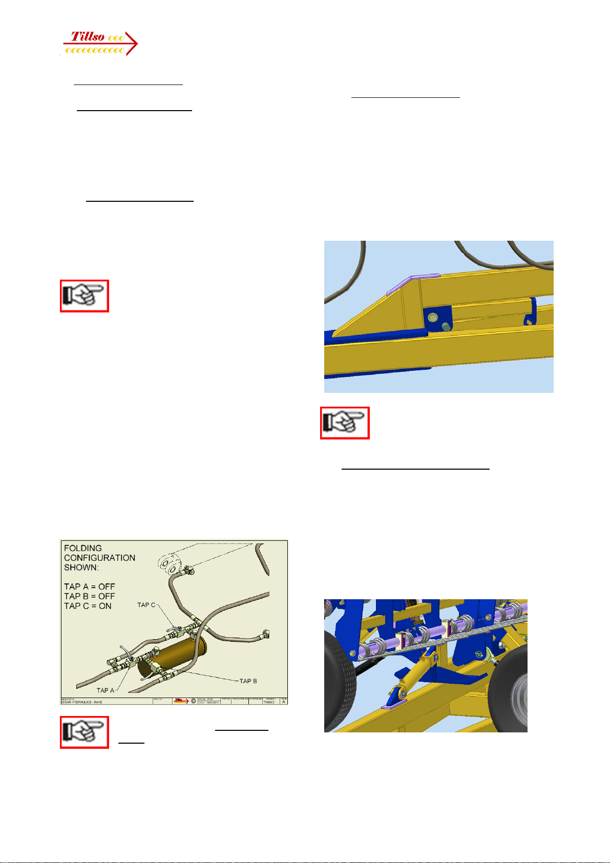
symbols are used:
Important!
Risk of injury!
Risk of fatal or serious
injury!
It is important that all the safety instructions
contained in these Operating Instructions
and all the warning signs on the machine
are read carefully.
Ensure that the warning signs are legible.
Replace any signs that are missing or
damaged.
These instructions must be followed in order
to prevent accidents. Inform other users of
the warnings and safety instructions.
Do not carry out any operations which may
affect safe use of the machine or component.

8 Operators Manual
1.2 Use for the Intended Purpose
This Rake & Roll machine is built using the
latest technology and in accordance with the
relevant recognised safety regulations.
However, risks of injury for the operator or
third parties and impairment of the
machine or other tangible assets can arise
during use.
The machine is only to be operated when in a
technically perfect condition and for the
intended purpose, taking into consideration
safety and risks and following the Operating
Instructions. In particular, faults that can
impair safety are to be remedied
immediately.
Original parts and accessories from TILLSO
have been specially designed for this
machine. Spare parts and accessories not
supplied by us have not been tested or
authorised. Installation or use of non-original
TILLSO or SIMBA products may have a
detrimental effect on specific design
features of the machine or component and
affect the safety of machine operators and
the machine itself. TILLSO will accept no
liability for damage resulting from the use of
non-original parts or accessories.
The machine is designed solely as a
cultivation implement, for raking straw and
crop debris and for surface rolling and minor
secondary cultivations. Use for any other
purpose, e.g., as a means of transport, will be
deemed to be improper use. TILLSO will
accept no liability for damage resulting from
improper use. The risk will be borne solely by
the operator.
Use of the Rake & Roll in conjunction with
any other machine (for example in a
cultivations train) is not permitted unless with
the express permission of TILLSO. The use
of machinery trains can be dangerous and
can contravene local road transport
regulations.
1.3 Operational Safety
The machine is to be put in operation only
after instruction has been provided by an
employee of the authorised dealer or an
employee of TILLSO. The "Machine
Registration" form is to be completed and
returned to TILLSO.
All protective and safety equipment, such
as removable protective equipment, must be
in place and functioning reliably before the
machine is put in use.
Check screws and bolts
regularly for tightness and
retighten if necessary.
In the event of malfunctions, stop
and secure the machine
immediately.
Ensure that any faults are
remedied immediately.
1.3.1 No Liability for Consequential Damage
This machine has been manufactured by
TILLSO with great care. However, problems
may still occur when it is used for the
intended purpose. These may include:
• Worn wearing parts.
• Damage caused by external factors.
• Incorrect driving speeds.
• Incorrect setting of the unit (incorrect
attachment, non-adherence to the Setting
instructions)
• Unexpected levels of crop residue.
Therefore, it is crucial to always check
your machine before and during operation
for correct operation.
Compensation claims for damage
which has not occurred to the
machine or its components are
excluded. This includes any consequential
damage resulting from incorrect operation
which may occur.

9 Operators Manual
1.4 Road Traffic Safety
When driving on public roads, tracks and
areas, it is important to observe the relevant
road traffic laws as well as the specific
regulations relating to this machine. As
transport regulations vary regionally, the
regulations which apply to your locality should
be complied with in terms of this machine.
Note specific requirements regarding
implement width, speed, and features such
as lights and brakes: ensure these are
complied with (for example keep to maximum
transportation speeds with machines if not
fitted with brakes, and/or according to
machine transportation width).
Actual dimensions relating to transport may
vary with adjustments, however the basic
dimensions of the Rake & Roll fall into the
categories as follow:
Overall transport width <3m
Overall transport height <4m
Fitting of components can alter
the machine configuration,
including, for example, its stability
in operation or transportation. It is important
to recognise such issues and ensure that the
safety of the machine, its components, the
Operator, and any Third Parties is maintained
at all times.
Pay attention to the permitted
axle loads, tyre carrying capacity,
and total weight in order to
maintain adequate braking and steerability.
Passengers on the machine are
strictly forbidden!
Max. road transport speed 16mph
(25km/h).
1.5 Accident Prevention
In addition to the Operating Instructions, it is
important to observe the accident prevention
regulations specified by the HSE, and any
agricultural trade associations.
It is the Operator's responsibility
to ensure that all other persons
are excluded from the danger
zones surrounding or on the machine or
component during its operation.
1.5.1 Hitching-up the machine
There is a risk of injury when hitching
and unhitching a machine. Observe the
following:
• Secure the machine against rolling.
•Take special care when reversing the
tractor!
• There is a risk of being crushed between
the machine and the tractor!
• Park the machine on firm, level ground.
1.5.2 Changing Equipment
• Secure the machine to prevent it from
accidentally rolling away!
• Use suitable supports to secure any raised
frame sections suspended above you!
•Caution! Risk of injury due to projecting
parts!
Never climb on to rotating parts
such as the roll unit. These parts
may rotate causing you to slip
and suffer serious injury!
1.5.3 During Operation
Ensure that the working range and the area
around the machine or component are
clear (be aware of Third Parties, especially
Children!) before operating the machine.
Always ensure adequate visibility!
Do not stand on the machine while it is in
operation!
Operators must have a suitable valid driving
licence in order to drive on public roads.
1.5.4 Machine Owners responsibilities:
It is the Owner's responsibility to ensure the
following regarding the machine or
component:
•the Operator is trained and competent
to use the machine & tractor, and has
read and understood the instructions
regarding their use;
•the tractor is suitable for the machine,
•the component is suitable for the
machine,
•adequate Risk and COSHH
assessments have been undertaken
regarding the machine's use,

10 Operators Manual
•the Operator is aware of the specific
regulations relating to the machine
when driving on public roads.
1.6 Servicing & Maintenance
Ensure that regular checks and inspections
are always carried out within the periods
required by law or specified in these
Operating Instructions.
When carrying out service and maintenance
work always:
• switch off the tractor engine and remove
the ignition key.
• wait until all the machine parts have
stopped moving.
• depressurize any hydraulic system. Note
many circuits contain lock or overcentre
valves which can retain pressure in the lines
even after depressurising the tractor side of
these circuits. If in doubt, consult trained
personnel (such as your local TILLSO or
SIMBA Dealer) to ensure such valves are
depressurised to the correct procedure before
removing or servicing any parts connected
downstream of these valves.
Prior to performing maintenance and
servicing work, ensure that the machine is
positioned on solid, level ground and is
secured to prevent it rolling away. Do not
use any parts to climb on to the machine
or component unless they are specifically
designed for this purpose.
Before cleaning the machine or component
with water, steam jets (high-pressure
cleaning apparatus) or other cleaning agents,
cover all openings into which, for reasons of
safety or operation, no water, steam or
cleaning agents are to penetrate (bearings,
for instance).
Next, check all hydraulic lines for leaks, loose
connections, chafe marks and damage.
Remedy any deficiencies immediately!
Pay particular attention to hose renewal
intervals as outlined in the specific sections
which follow. ALL hydraulic hoses have a
safe maximum working life of 6 (SIX) years
from date of installation, provided they remain
in a safe condition. Hoses which exceed 6
years of age should be replaced, or inspected
and certified by a suitably qualified person to
have an extended life period which should be
recorded.
Lubricate all the lubricating points to force
out any trapped water.
In the case of hydraulic cylinders that have
been cleaned using high pressure equipment
ensure that all hydraulic circuits are functional
and pressurised fully in both directions. This
provides the necessary coating of oil onto
cylinder rods after cleaning.
When carrying out servicing and maintenance
work, retighten any loose screw connections.
Pay particular attention to those
items which require specialist
service tools or training to be
carried out by qualified personnel. Do not
attempt to service these items yourself!!
These include items retaining pressure (e.g.
accumulator circuits), or force (e.g. spring
tines), and DD axles of any type.
1.7 Operating Areas
The operating areas include the drawbar,
hydraulic connections and tine adjustment
equipment as well as all operating points
requiring maintenance.
All operating areas will be specified and
described in detail in the following chapters
on servicing and maintenance.
Observe all safety regulations included in the
Section dealing with Safety, and in the sub-
sequent sections.
1.8 Authorised Operators
Only those persons who have been
authorised and instructed by a fully trained
operator may operate the machine. The
operator must be at least 16 years of age.
1.9 Protective Equipment
For operation and maintenance, you require:
• Tight fitting clothing.
• Strong protective gloves (to provide
protection against sharp-edged machine
components: Note components may become
sharp following use and wear).

11 Operators Manual
• Protective goggles (to stop dirt getting into
your eyes).
2. Transportation and Installation
Transportation and initial installation of the
machine or component are described in this
chapter.
2.1 Delivery
A machine is normally delivered in a fully
assembled state. Consult TILLSO or your
Dealer for advice on initial removal from
transportation means such as low loaders.
• A complete machine can normally be
hitched to a tractor and driven off a low-
loader.
2.2 Transportation
The machine can normally be transported on
public roads by hitching it up to a tractor or on
a low- loader.
• It is important to observe the permitted
dimensions and weights when transporting
the machine.
• If the machine or component is transported
on a trailer or a low-loader, it must be
secured using straps or other devices.
• Before transporting a machine on public
roads, it must be adjusted to its transportation
position and the stipulations relating to road
transportation fulfilled.
• The maximum permissible speed in
transport is 25km/h (16mph).
2.3 Installation
When carrying out installation
and maintenance work there is a
higher risk of injury. It is
important that you familiarise yourself with
the machine and read the Operating
Instructions beforehand.
Operator instruction and initial installation of
the machine are carried out by our service
technicians or authorised distributors.
The machine must not be used in any way
beforehand! The machine can only be
released for operation after instructions have
been provided by our service technicians or
authorised distributors.
• If any modules or parts have
been removed
for transportation, or the item is a
component rather than a fully complete
machine, these shall be mounted by our
service technicians/authorised dealers before
the instruction takes place.
• Check all important screw connections!
• Lubricate all nipples and joints!
• Check all hydraulic connections and lines
for damage.
3. Technical Data:
Rake & Roll 8m:
Working width: 8450mm
Overall width in work 8580mm
Overall length in work: 7900mm
Transport width: 2995mm
Transport height: 3800mm
Transport length: 5800mm
Total weight 5250kg
Axle load in transport: 3800kg (37278N)
Drawbar load in transport 1450kg (14225N)
Maximum drawbar uplift 1000kg (9810N)
Maximum drawbar pull provided for: 125kN
Power requirement 150/200Hp
Rake & Roll 12m:
Working width: 12250mm
Overall width in work 12380mm
Overall length in work: 9325mm
Transport width: 2995mm
Transport height: 3990mm
Transport length: 7150mm
Total weight 6800kg
Axle load in transport: 4400kg (43164N)
Drawbar load in transport 2400kg (23544N)
Maximum drawbar uplift 1250kg (12263N)
Maximum drawbar pull provided for: 125kN
Power requirement 200/275Hp
12 Operators Manual
4. Adjustment/Operation
4.1 Preparing for operation
The Rake & Roll is normally delivered ready
for operation. In the event that the machine is
delivered part-assembled, do not attempt to
assemble or operate the machine before
consulting TILLSO.
4.1.1 Hitching to the tractor
Hitching to the machine when folded on its
parking stand is accomplished via a normal
tractor pick-up hitch operation. Ensure the
machine is on firm, level ground and reverse
the tractor to engage the hitch.
NOTE: if a tractor is used not
having a pick-up hitch, the
machine should be on- and off-
hitched unfolded in the work position to allow
use of the tilt cylinders to raise the drawbar.
Once hitched and the hook locked, the
hydraulic pipes can be connected. The pipes
are colour coded according to the cylinder
ports with similar colours. There are 2 main
circuits for the all machines:
RED: Tilt (to raise for turning & return)
BLUE: Fold (note used in conjunction with tilt)
A further circuit is present on the 12m
machine only:
GREEN: Wing transport support on drawbar
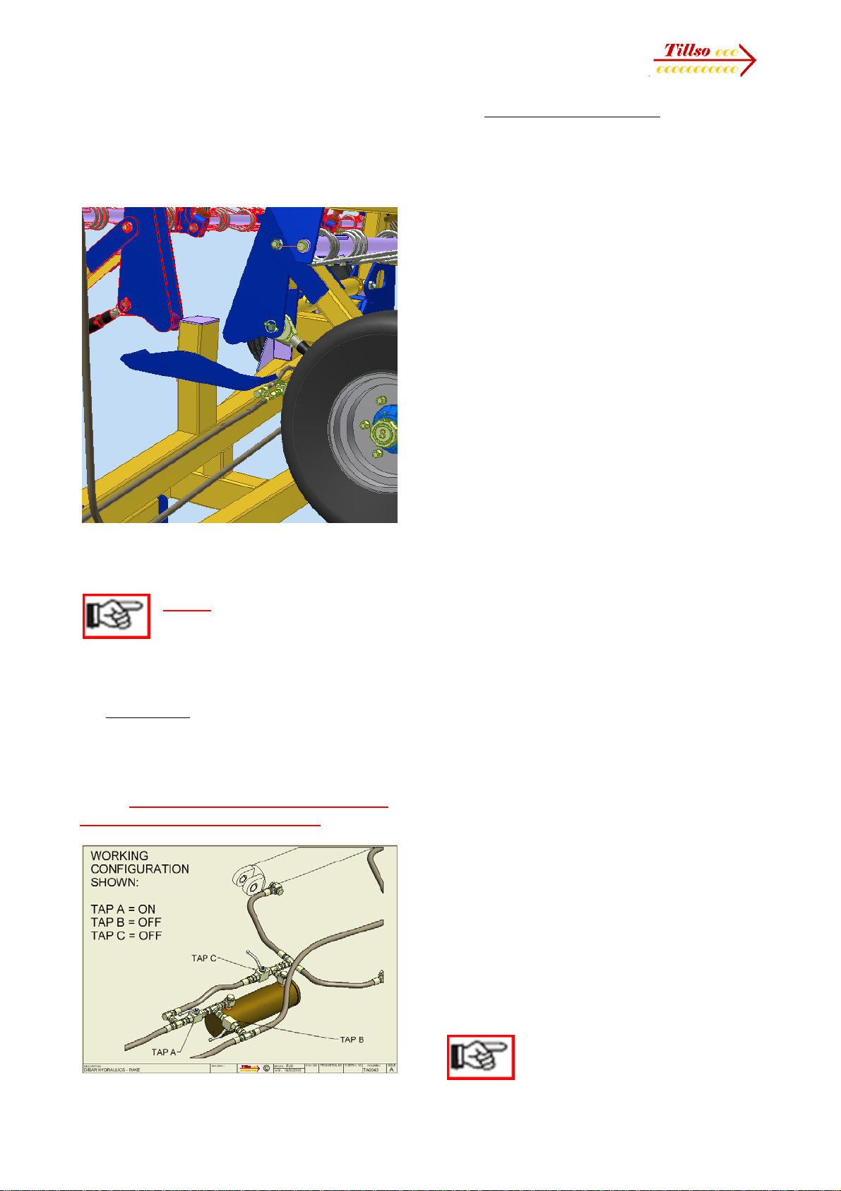
Before activating the hydraulics, ensure the
tilt circuit taps are set as per below:
This setting should always be
used when folding, unfolding, or
parking the machine. Detailed
instructions on the use of this circuit follow in
section 4.3.2.
4.1.2 Transportation to field
Ensure the machine is correctly hitched to the
tractor, and all hydraulic lines are coupled
and locked (hydraulics in neutral or lock).
Ensure that secondary wing locks are fitted.
Ensure wheel nuts are correctly tightened
(see maintenance section).
Raise and lock the parking stand in its work
position. Ensure light boards are secured.
NOTE: maximum transport speed
for machines not fitted with brakes
is 25kph.
4.2 Preparing for work - unfolding
Ensure the machine is to be unfolded on firm,
level ground and the area for unfolding is
clear of any third parties.
Ensure the tilt circuit taps are set as the
preceding figure (section 4.1.1).
Remove any secondary wing locking devices,
and on 12m machines lower fully the
transport support arm.
Remove the light board and stow as
appropriate. Note this can be stowed on the
machine, or away from it if preferred to
13 Operators Manual
minimise vibration damage to bulbs. Ensure if
away from the machine that it is available for
subsequent fitting as needed.
Tilt the machine slightly rearward to clear the
rigid support stand on 8m machines.
Unfold fully the wings, then tilt fully rearward
to lower the machine to ground level.
NOTE: whilst lowering the
machine by tilting rearwards,
drive slowly forwards to
minimise damage to the rake tines as they
contact the ground.
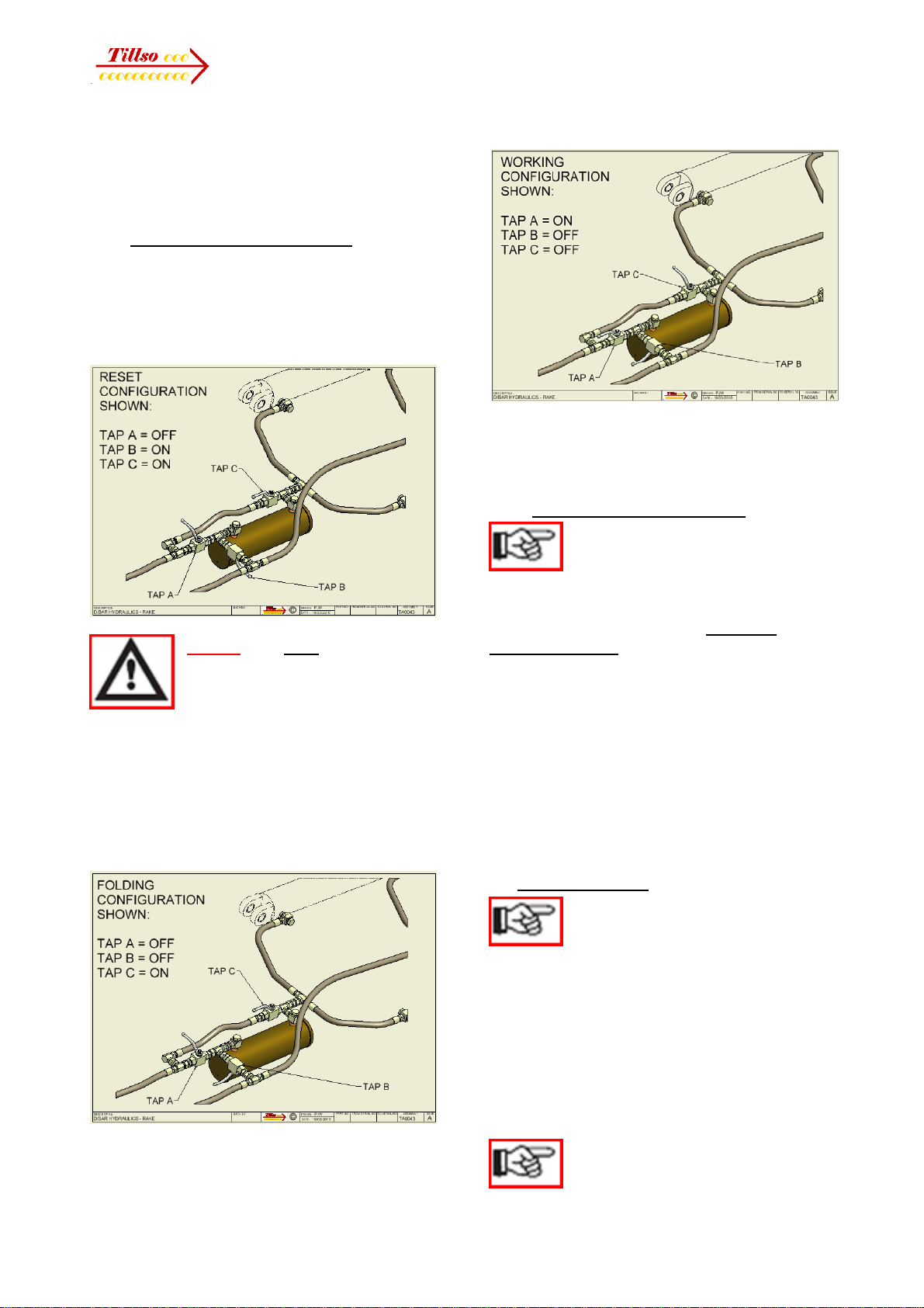
4.3 Field setting
If the pre-set pitch is in use (see next section
for details), provided the machine is unfolded
and fully tilted rearwards, at this position
change the tap settings to the work setting as
below. Turn any taps off which will remain
so before turning the others on!!
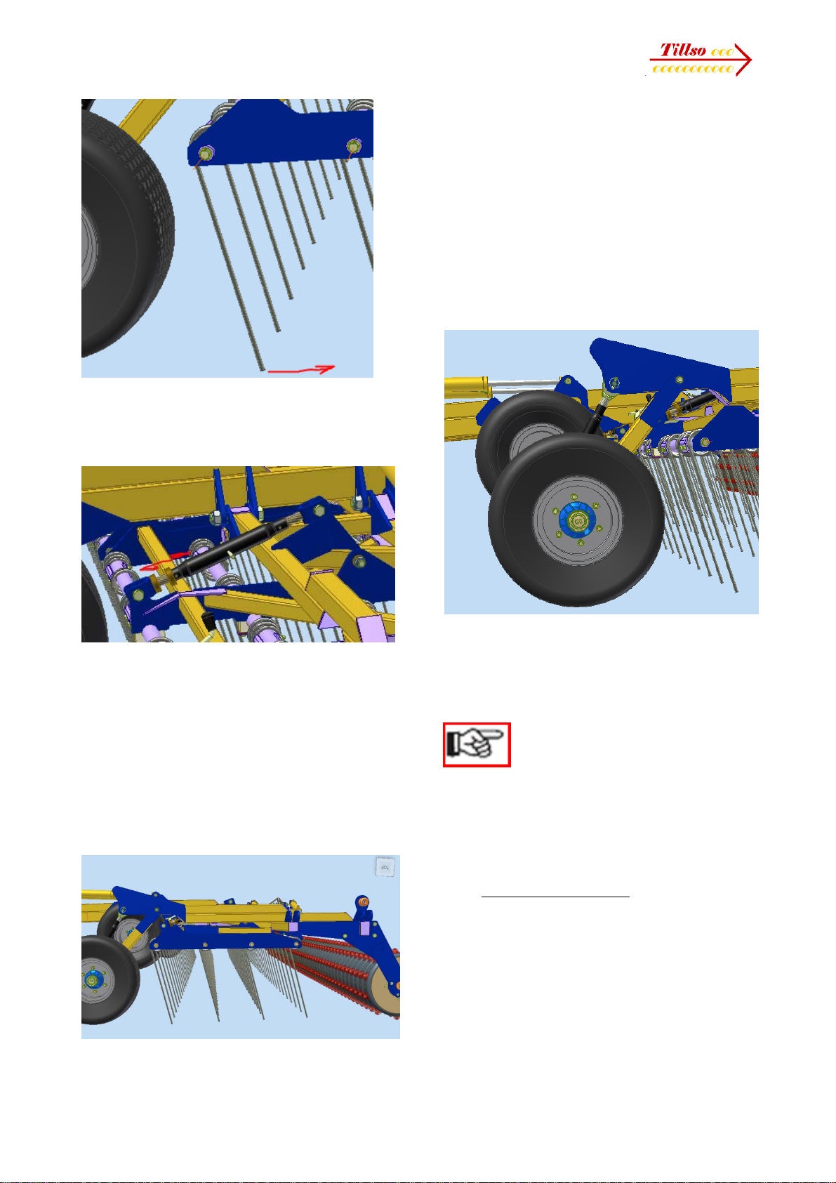
4.3.1 Adjustment of frame pitch
Depth control of the rake tines is controlled by
the frame pitch, using the rear rollers to
maintain the desired tine setting. Additional
adjustment of the tine angle (see section
4.4.1) allows for effectiveness of straw carry,
and of tilth making when rolling seedbeds.
Any major adjustment of the machine pitch by
the main tilt cylinders may require the tine
frames to be adjusted by their toplinks to
maintain an even depth of tine tips fore to aft.
See section 4.4.1 for further details.
Setting of this pitch is by the main tilt
cylinders. These can be manually controlled
on the move by the tractor hydraulics, or the
desired pitch can be set via the adjustment
circuit. This returns to a pre-set position when
tilting downwards from the fully rearward
position for turning. This can be achieved by
operating the circuit in float (preferred) or
lower after a turn is made.
The tilt control can be initially set (this also
resets the circuit), adjusted to fine tune and
lock this setting, and memorise this setting
when folding so this position is available after
unfolding to start in another field.
The design of this system uses a closed
hydraulic cylinder with an internal piston. This
allows for the tilt position to be set (piston at
one end of the cylinder) and tilted rearwards
for turning (piston between this end and the
opposite end). When returning into work, the
locked oil then drives the piston back to its
original position in the cylinder to maintain the
desired pitch. Oil is introduced or taken from
the part of the circuit between this cylinder
and the tilt cylinders to alter the pre-set pitch
as needed. The cylinder is isolated when
folding and provided the sequence of
isolation is followed, the originally set tilt
position is maintained when unfolding in the
next field.
The tilt circuit can also be operated with the
tilt control disabled, allowing for simple tilting
rearwards and forwards without a pre-set
position. See the next section for this detail.
NOTE: it is normal not to raise
and lower when turning so straw
can be collected from the
14 Operators Manual
headland area and spread out progressively
across the field. Consequently, the frame
pitch is not constantly being adjusted unless
field conditions and straw concentrations vary
significantly.
4.3.2 Setting the Tilt Control Circuit
To adjust and then remember a new pitch
setting, firstly reset the circuit as follows.
Fully tilt the rake rearwards. In this position,
set the taps to reset, as below. Pressure
rearwards again fully.
NOTE: take care when
changing tap settings as
some movement of the
machine can occur which can
reduce the rearward pitch a little. Turn any
taps off first which will remain off.
Pressure rearwards fully to reset the circuit.
Next, still tilted rearwards fully, set the taps to
fold, which allows the machine to be operated
without the pitch control.
Operate the machine until the desired pitch is
obtained.
Whilst at this pitch, change the taps to the
working setting. The pitch is now memorised.
The machine can be tilted rearwards, upon
releasing this pressure it will return back to
the desired pitch.
4.3.3 Fine tuning the Pitch Setting
Once a pre-set pitch is in use it
can be fine tuned without going
through the resetting procedure.
In the working configuration (above figure),
ensure firstly the machine is fully tilted
forwards, in work. If this is too high or low,
adjust as follows.
Change over the tap settings to the fold
configuration (figure, below, left) and then
adjust the pitch until the required setting is
achieved.
this new position, change the taps back to the
working setting (figure, above) to memorise
the new position.
4.4 Work to transport
Follow the procedure outlined
below to keep the pre-set pitch for
next time before folding and
unfolding.
With the machine fully tilted rearwards,
change the taps to the fold setting as
illustrated opposite.
Remember when adjusting tap settings to
turn those off first which will remain off.
Provided the tap settings are
changed over from work to
fold and back with the machine

15 Operators Manual
unfolded and fully tilted rearwards, any
pre-set pitch will be retained.
The machine should always be folded and
unfolded with the circuit taps set in this
configuration.
To fold up, tilt the machine forwards fully,
then fold in the wings. On 8m machines, just
before completing the fold, tilt slightly back to
allow the wings to clear onto, and above the
drawbar located supports, then fully fold.
Finally lower the wings onto the supports and
fit any secondary transportation locks.
On 12m machines, once fully folded, raise the
transport stand to take some weight of the
wings, then lock the support stand tap and fit
any secondary transport locks.
NOTE: THE MACHINE CAN
BECOME UNSTABLE IF
FOLDED OR UNFOLDED ON
SLOPING GROUND.
Always choose a firm level surface for folding
or unfolding. Always face the machine
upslope and not across slope so that the
wings are sitting horizontal when unfolded.
TAKE CARE IN TRANSPORT!
THE CENTRE OF GRAVITY IS
HIGH WHEN FOLDED AND
THE MACHINE COULD
BECOME UNSTABLE ON SEVERELY
SLOPING GROUND, ESPECIALLY WHEN
TURNING.
The machine is stable when static on slopes
of up to 15°, however avoid such situations
whenever possible.
4.5 Parking
On tractors having a pick-up hitch, choose a
level, firm surface for parking.
With the machine folded, lower the drawbar
stand and pin in position. Unhitch normally.
Where tractors are used without a pick-up
hitch, it is recommended that the machine is
parked unfolded, fully in ground contact.
The tilt circuit hydraulics can be used to
support the drawbar safely when unhitching.
Drive forwards enough to allow the drawbar
to be lowered onto its stand, de-pressurise
the tilt hydraulics and uncouple.

16 Operators Manual
4.6 Aqueel 2 Roller
The Aqueel 2 is a rubber, specialist self-
cleaning tyre which leaves a patterned
surface profile consisting of conical
indentations. This is designed to combat
surface water movement and wind erosion in
the field. The benefit of Aqueeled ground
(reservoir tillage) is gained on light, easy
working soils that can slump or compact.
4.7 Work Settings
In practice it is possible to use a DD or
Aqueel roller on ground conditions that
are unsuitable to achieve the desired effect,
and it is usually possible to operate such
rollers without regular blockage under such
unsuitable conditions, assuming that the roll
assemblies are tight, the scrapers correctly
adjusted and rings smooth. As such,
especially under wet conditions, it is
advisable to check on the cultivation effect of
the machine fitted with such rollers, as these
normally do not limit the machines effective
use.
The machine can be lifted clear of the ground
for headland turns if the tine cultivation effect
is not needed. Generally, when being used as
a straw rake keep the machine in its working
setting at all times to maximise the straw
levelling effect.
If straw builds up excessively, tilt rearwards
slightly to allow the straw to be spread out
over the field. It is normal for straw to build up
and diminish as the process of evening up
the levels of residue occurs.
Often heaps on the headlands will cause a
temporary blockage but this will be lost down
the field, achieving the desired effect.
Excessively tight turning could
lead to damage of the tine
components!. Avoid sections of
the machine going rearwards at all costs
otherwise tine breakage will occur.
4.7.1 Tine adjustment and setting
The rake tines can be adjusted for pitch
according to conditions. As a general guide,
the steeper the tine the more aggressive the
cultivation and raking effect.
Avoid setting the tines too far tips
forwards that they contact the
main axle wheels when folding.
It is normal to set the tine depth and straw
holding capacity by the rear roller. This allows
for tine angle to be set for the desired
cultivating effect.
If straw blocks regularly, initially raise the
tines by tilting the rake rearwards slightly on
the roller. If additional clearing is needed,
increase the rake angle of the tines (angle
tips rearwards).
17 Operators Manual
Any major adjustment of the machine pitch
and depth by the main tilt cylinders may
require the tine frames to be adjusted by the
toplinks to maintain an even depth of tine tips
fore to aft.
Lengthening the toplinks increases front tine
depth which compensates if the main
implement pitch has been tilted rearwards;
and vice versa.
When cultivator-rolling, the tines can be used
to fine up the tilth and provide improved seed
to soil contact by finer aggregation.
Tines should be running at the same depth
for all rows with the toplinks correctly set.
Avoid running the tine frames nose deep; if
more tine pressure is needed tilt the main
machine forwards and then shorten up the
tine frame toplinks so the tine depth is
consistent front to rear.
Set tine depth to the minimum needed for the
surface finish. Set this by adjusting the tilt
setting (main machine pitch) and levelling the
tines fore to aft by the turnbuckles as per
above.
The wing wheels (if fitted) should be set to
just maintain ground contact at the desired
working pitch and depth.
The main centre axle wheels will normally be
clear of the ground in working mode, allowing
the roller to control the depth across the full
machine width.
NOTE: the wing wheels act as
stabilisers and control the wings
when unfolding and folding. As
such, they should be set to within ground
contact wherever possible in work. This also
avoids undue pitching of the wider machines
in work if the ground is unlevel across the
width.
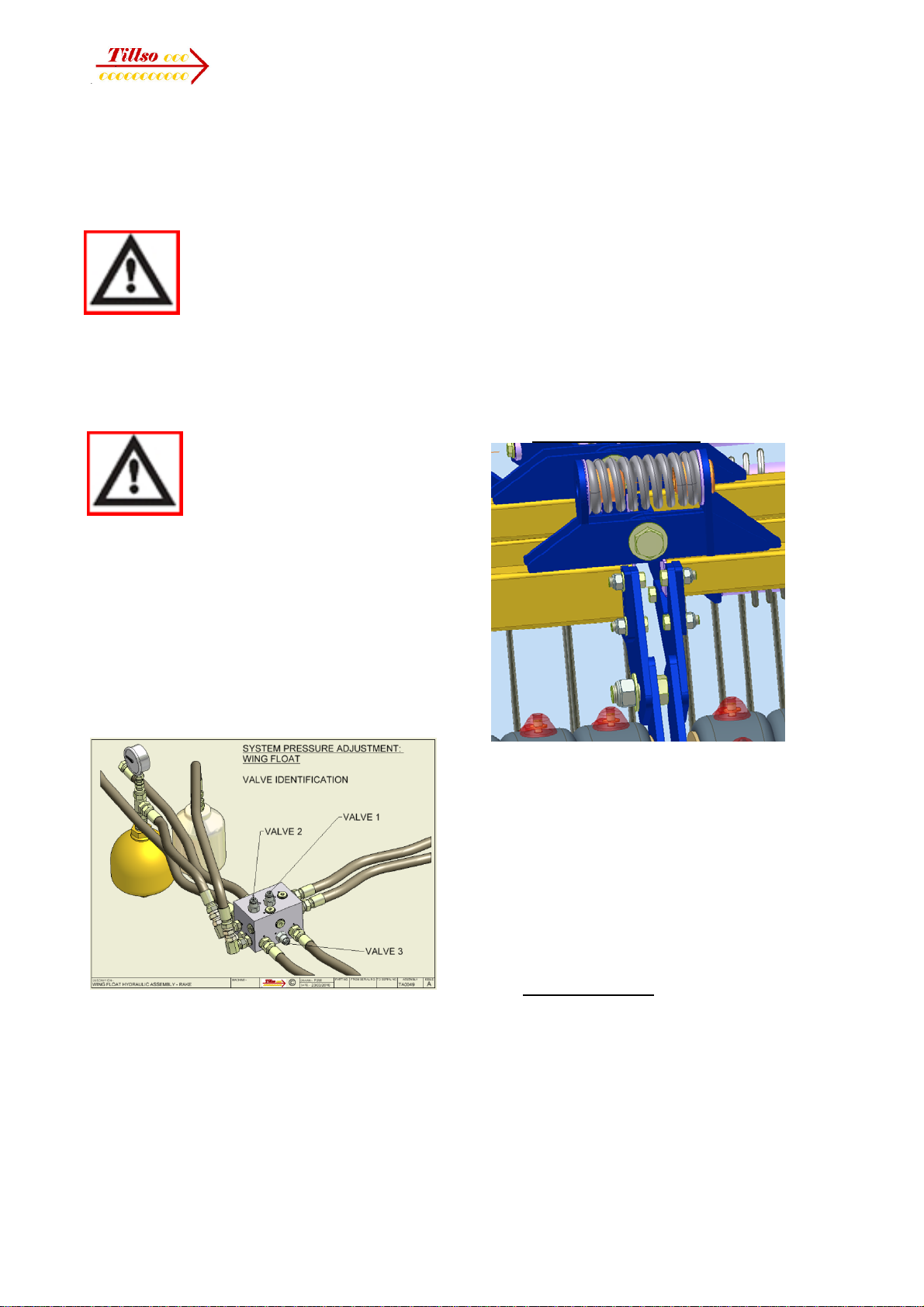
4.7.2 Wing float adjustment
The wings can float over undulations via an
adjustable cushioned suspension system
which is pre-set hydraulically (inner wings) or
via springs (outer wings - 12m only).
The inner main wings are held by oil in the
folding cylinders against an accumulator. This
pressure is adjustable if needed via the valve
block as detailed below.
18 Operators Manual
Wing pressure can be checked and adjusted
as follows. Always minimise tractor oil flow
rate provided folding speed is adequate.
Excessive oil flow leads to high temperatures,
inconsistent and inefficient valve operation.
This circuit is controlled by
overcentre locking valves
located in the valve manifold
block. These positively lock oil
pressure holding the wings until
pressurised by the tractor when folding or
unfolding to release it. System pressure can
be retained even after depressurisation of
the tractor quick release couplings.
Take extreme care when
checking the valve and circuits
adjacent. Under no
circumstances attempt to
loosen or remove fittings
without prior reference to your TILLSO
authorised Dealer or TILLSO directly.
With the machine in working setting, tilt
forwards to raise the rear end half-way to 45°,
then pressure the wings to unfold fully.
Pressure the circuit until the gauge has
reached a constant maximum value. Return
the machine to ground contact and check for
evenness of ground pressure. Note the
gauge (holding down) pressure at this point.
If excessive down pressure is present at the
wing tips, pressure in the circuit should be
reduced. Adjust valve 3 anticlockwise to do
this. To confirm the setting is improved,
partially tilt the machine forwards, then
partially fold the wings. This releases
pressure in the circuit. Then unfold fully and
pressurise as above before returning the
machine to its working position. The gauge
should now read a reduced value. Continue
this operation sequence until the desired
down pressure is achieved.
Should the pressure require increasing,
repeat the above sequence whilst turning the
valve clockwise
The amount of over-centre valve holding
pressure resisting oil leakage back to the
tractor is adjusted by valves 1 and 2;
clockwise to increase hold pressure. These
valves can be used to reduce the holding
pressure if de-pressurisation is required.
Consult TILLSO if this is required.
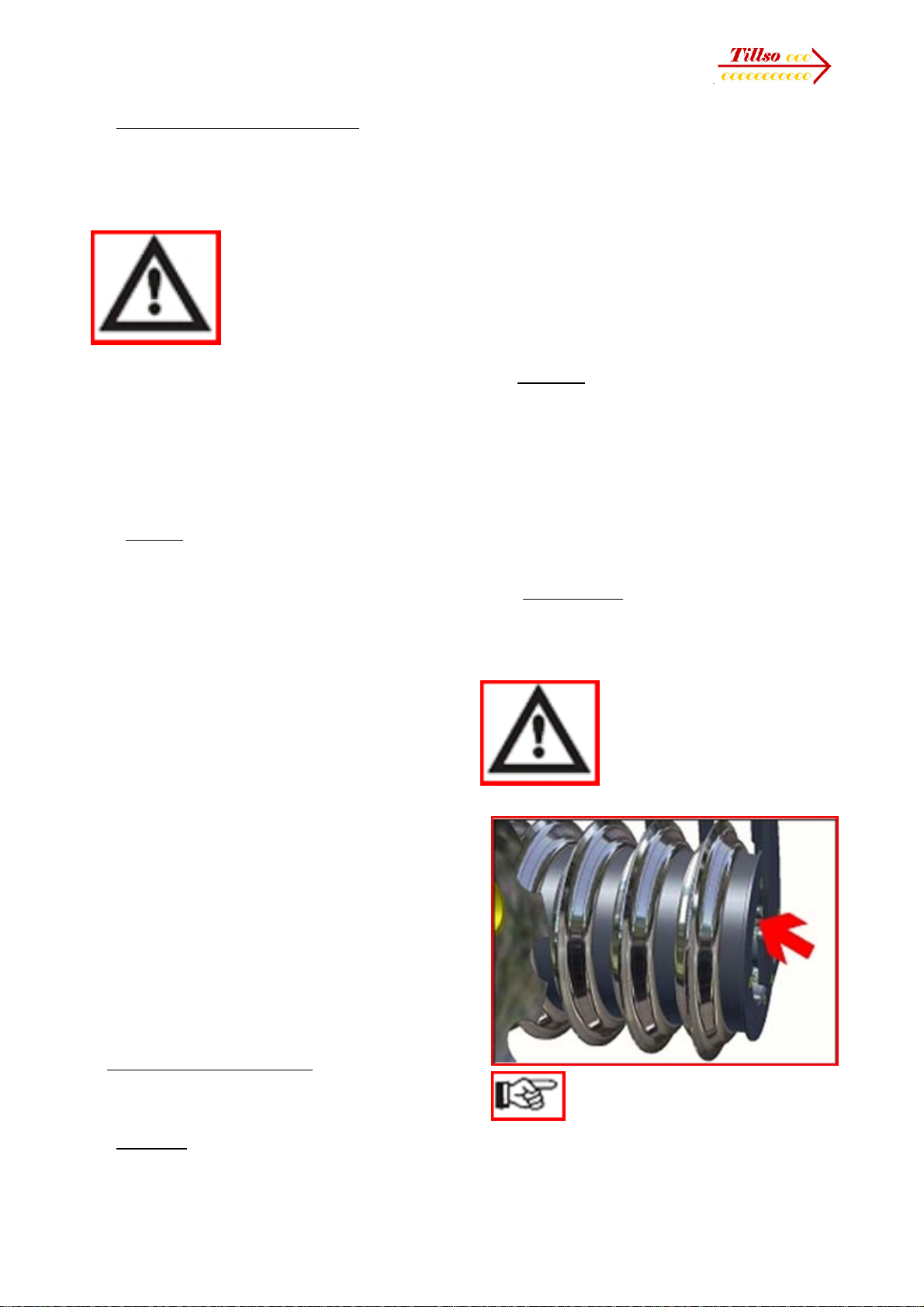
4.7.3 Outer wing float (12m)
A spring controls the weight transferred from
the inner to outer wings. This is shimmed
during assembly. A stop bolt limits the down
float with shims to fine tune this.
Consult TILLSO if any servicing is needed on
this component. A clamp bolt is needed to
release the spring pressure when unpinning
the outer wings to allow the unit to be taken
apart.
4.8 Work Instructions
Driving speed:
12 -15 km/h for raking; 6-8 km/h for
cultivation rolling is normal.
This depends on the field conditions (type of
soil, surface trash, etc.).
Drive more slowly if the conditions are difficult
or a firmer finish is required.
19 Operators Manual
4.9 Parking the machine (long term)
In order to avoid damage as a result of
moisture or ultra-violet sunlight rays, the
machine or component should be parked, if
possible, indoors or under cover.
When manoeuvring the
machine, pay attention to
your surroundings.
Ensure that nobody is in
the manoeuvring area
(watch for children!).
• Park the machine on level and solid ground.
• Lower the machine onto its parking stand
ensuring that it is stable when unhitching from
a tractor pick-up hitch.
• Ensure undue weight is not applied through
the tines if parked unfolded (for example, with
tractors not having a pick-up hitch).
4.10 Checks
The working quality depends on the
adjustments and checks made prior to and
during work, as well as on regular servicing
and maintenance of the machine.
Before beginning work it is therefore
important to carry out any necessary
servicing and to lubricate the machine as
required.
Checks prior to, and during work:
• Is the machine correctly installed?
• Is the machine correctly hitched up and any
coupling device locked?
• Have any hydraulic lines been connected
according to the colour coding?
• Is the machine in a level operating position
and the working depth set correctly?
Working Elements
• Are the cultivation tools in a serviceable
condition?
• Are the scrapers (if fitted) still operable, so
that the rolls do not jam?
• Are the DD axles tight to avoid wear?
5. Servicing and Maintenance
Follow the safety instructions for
servicing and maintenance.
5.1 Servicing
Your machine has been designed and
constructed for maximum performance,
operational efficiency and operator
friendliness under a wide variety of operating
conditions.
Prior to delivery, your machine has been
checked at the factory and by your authorised
dealer to ensure that you receive a machine
in optimum condition.
To ensure trouble-free operation, it is
important that servicing and
maintenance work is performed at
the recommended intervals.
5.2 Cleaning
In order to ensure that the machine is always
in operating condition and to achieve
optimum performance, perform the cleaning
and servicing work at regular intervals.
Avoid cleaning the roll / disc bearings with a
high- pressure hose or a direct water jet. The
housing, screwed connections and ball
bearings are not watertight.
5.3 DD Light Roll
The spacers and rings on the DD Light Roll
are held under tension by the end plates at
the outer ends of the roll tube.
Specialist equipment is
required for the
disassembly of DD Light
rollers. Please consult
your dealer under any
circumstances that
require disassembly of these rollers.
Maintenance of these rollers is
limited to yearly/end of season
greasing of the bearings
and regular inspection to ensure the
assemblies are tight, and scrapers are
correctly set.

20 Operators Manual
The scraper is intended to clear
dirt from blocking between
adjacent DD rings. If adjustment
to the scrapers is required ensure that the
scraper cannot contact the spacer even
under load. Regularly inspect the spacers for
signs of wear and adjust any scrapers to
ensure no contact can be made.
5.4 Aqueel Rolls
Maintenance of Aqueel rollers is limited to
seasonal greasing of the bearings to ensure
grease is present, and regular inspection to
ensure the assemblies are tight, and any
stones trapping between wheel elements are
removed. Do not over-grease sealed
bearings otherwise seal damage will occur.
Additionally, regularly check roll elements for
abrasion, wear and cutting. Replace as
necessary. If in doubt about replacing wheels,
consult TILLSO or your local TILLSO dealer
for guidance.
5.5 Pitch Control Circuit - Purging & re-setting
If at any time the circuit needs to be purged of
air, or reset, use the following procedure.
Ensure the machine is in working position,
unfolded in full ground contact (not tilted
rearwards).
Set the system taps as the following
illustration, remembering to initially turn any
taps off which need to remain off.
In this setting, work the tilt circuit pressuring
either side in turn, holding for a few seconds
under pressure. Alternately pressure either
side at least 3 times.
NOTE: when lowering back into ground
contact drive forwards slowly to minimise
damage to the tines.
Finally finish this cycling with the machine
fully pressured rearwards, tilted back, then
set taps to the fold configuration:
In this setting the pitch control is disabled.
The machine can be operated without the
pitch control, manually adjusting for pitch
according to conditions. It can also be folded
and unfolded.
5.6 Preparation for Storage
If you need to store the machine for a longer
period, observe the following points:
• Park the machine undercover if possible.
• Protect the roll / other elements against rust.
If you need to spray the implements with oil,
use light biologically degradable oils, e.g.
rape oil.
Cover any rubber or p/u sections
before using oil sprays. These
sections must not be oiled.
Remove any traces of oil with a suitable
cleaning agent.
5.6 Operator Support
If you have a problem, please contact your
dealer, or TILLSO. In order to enable your
dealer to deal with problems as quickly as
possible, it helps if you can provide them with
the following data. Always state the:
• Customer Number
• Name and Address
• Machine Model
• Serial Number of Machine
• Date of Purchase and Operating Hours
Table of contents


