AMVAC SmartBox User manual

Parts and Operator’s Manual

Introduction
CONGRATULATIONS! By purchasing the SmartBox®system, you have obtained the
world’s rst variable-rate, speed-compensated and totally enclosed system for the
application of low-rate granular insecticides. The SmartBox®system was created to
allow granular insecticides to be applied accurately, efciently and safely to your crops.
The information presented in this Parts & Operator’s Manual will introduce you to the
components of the SmartBox® system; provide step-by-step instructions on how to
install the system on your planter, and lead you through the programming and operating
steps required to obtain the most accurate application and record keeping possible.
Please read all of the information in Section A before proceeding to Sections B, C, D
and E. Section A will tell you the tools needed for installation and operation, as well as
give you helpful hints to make installing the system as effortless as possible.
From all of the employees at AMVAC Chemical Corporation who have worked to offer
you the SmartBox® system, we are condent that you will enjoy the many benets
of our product. Should you have any questions or comments, please feel free to
contact your local AMVAC sales representative or call our Customer Service Center
at 1-888-SMARTBOX (1-888-762-7826). You may also write to us at the following
address:
AMVAC Chemical Corporation
Attn: SmartBox®Customer Service
2110 Davie Avenue
Commerce, CA 90040
www.amvac-chemical.com or www.amvacSmartBox.com
SmartBox® is a registered trademark of AMVAC Chemical Corp.

TABLE OF CONTENTS
Safety Precautions
Warranty
System Installation Section A
System Overview
System Description
What’s Included
What’s Not Included
How to Get Started
Installation
Controller System
Row Units
Transfer Container
Wiring Cables
Lift Switch (Whisker)
Appendix A
Planter Drawings
System Setup Section B
Controller Setup
Controller Functions
RowConguration
PlanterConguration
Speed Calibration
Grouping
Console Adjust
Chemical Information
Computer Setup Section C
Installation of SmartBox®System Manager
System Manager Setup
SmartBox®System Manager
Add a New Controller
Set Current Controller
Data Download
Clear All Controller Info
Delete a Controller
(Continued Next Page)

Computer Setup
(continued) Section C
Grower Information
Add a New Grower
Update Grower Info
Delete a Grower
Print Grower Info Report
Operator Information
Add a New Operator
Update Operator Info
Delete an Operator
Print Operator Listing
Field Information
Update Field Info
Print Field Listing
Report Options
Printing Reports
Operations
Section D
Pre-Season Checklist
Operation
Transfer Container
Meter Calibration
SmartBox®Calibration Record
Replacing a Meter
Speed Calibration
Select Field Number
Field Cal Adjust
On/Off
Set Weather Specs
AB Control Switch
Area Information
Variable Rate
MPH...Area Monitor
Troubleshooting
2013 SmartBox System Trouble
shooting Section E
Troubleshooting
Speed Calibration
Meter Calibration
Meter Catch Test
Guide for Operation
System Application Issues

4
A

5
A
5
System Overview
System Description:
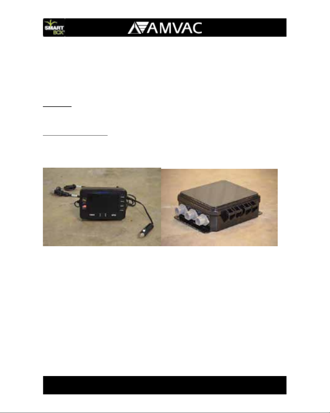
The SmartBox®System is a closed transfer and application system which uses electron
-
ically controlled metering technology to accurately and safely apply low-rate granular in-
secticides. The system features a controller which can store and record the necessary
information required by the Environmental Protection Agency (EPA) for record keeping.
The controller can easily download the stored information to a personal computer at the
user’s convenience. Information can be transferred to a Widows based personal com-
puterusingaUSBashdrive.AWindowsbasedrecordkeepingsoftwareprogramis
also included with the system.
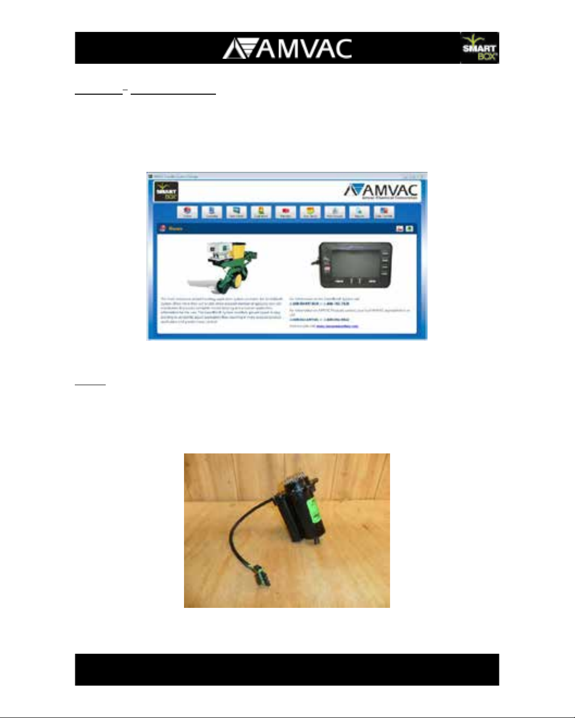
An added feature of the SmartBox®System is the ability to enter controller information
and function into the supplied AMVAC SmartBox®system manager software and trans-
fertothecontrollerusingaUSBashdriveforeasiersetup.
The SmartBox®Systemprovidestheoperatorwithon-the-goexibilitytomonitorand
change various operation parameters or set the system and allow it to run automatically.
The controller, which mounts inside the tractor cab, enables the user to quickly change
thechemicalapplicationrateorshutoffowtoone,all,oranycombinationofplanter
rows.
Input from a lift switch mounted on the planter will shut the system off when the planter
is raised. Audio and visual alarms on the controller alert the user of a possible plugged
rowtube,non-owingmeter,oranemptychemicalbox.
The accuracy of the SmartBox®system is elevated if true ground speed is measured
using radar, GPS, or another true wheel speed measurement device. With accurate
speed input and proper calibration, the meters will automatically compensate for varia-
tions in planter speed to keep the chemical application rate accurate. If true ground
speedisnotavailable,axedplantingspeedcanbeentered,butapplicationaccuracy
willdependonhowclosetheactualgroundspeedmatchesthexedspeedenteredin
the controller.
The SmartBox®System requires an activation code for use. Users are required to
register and activate their SmartBox®System annually. Upon registration the user will

6
A
receive any updated software that has been released. Updates can be easily installed
on your SmartBox®controllerusingaUSBashdrive.
The SmartBox®System can be registered by going to www.AMVACsmartbox.com.
AMVAC SmartBox®Home Web Page

7
A
What’s Included:
The AMVAC SmartBox
®System consists of the components listed below. All compo-
nents will be received in the quantities required for your planter according to the manu
-
facturer, row count, planter fold type, and row mounting bracket style (if required).
Controller:
The controller is the central control of the SmartBox®System. It is installed
in the tractor cab and connects to the 12-volt power port located in the tractor cab.
A mounting bracket and hardware is included.
Power Distribution Box:
The power distribution box controls the communication and
regulates the power supply to each meter. It is mounted at the center of the main plant
-
er bar near the row units.
Controller Power Distribution Box

8
A
SmartBox®System Manager:
The SmartBox®System Manager software can be used for setting up your controller
and storing application information.
The SmartBox System Manager software is a Windows based PC program that is
compatible with Windows XP – Service Pack 3, Windows Vista, Windows 7 and
Windows 8.
AMVAC SmartBox®Home Web Page
Meter: The meter is attached to the base container and includes both the metering
deviceandaowsensor.Oncethemetersarecongured,thecontrollerisabletoiden
-
tify the exact meter and row number if a problem occurs. A 30” vinyl braided tube, hose
clamp, gasket, and meter screen is also provided with each meter.
Meter

9
A
Wiring Cables: Cables included with the system include
:tractor harness, (30 or 60
Amp) planter harness, (30 or 60 Amp), console pigtail harness, row adapter cables,
4-row harness and 8-row harness, and meter extension cable. These cables make
electrical and communication connections between the controller and meters.
30
Amp tractor and 30 Amp planter cables are for use on system 23 rows and less.
60 Amp tractor and 60 Amp planter cables are for use on systems 24 rows and greater.
Lift Switch:
The mechanical lift switch with cable is used to signal the controller that the
planter is either in the raised or lowered position. This input tells the controller when to
start and stop the meters to avoid discharge of chemical when the planter is in the up
position. The lift switch is connected directly to the power distribution box.
Lift Switch

10
A
Base Container: The base container will hold a range of 10 to 12 pounds of chemical.
Each base container comes with a rain cover for use when a transfer container is not
installed.
Base Container
Universal Mounting Cradle:Theuniversalmountingcradleisdesignedtotontomost
major planter manufacturers’ existing insecticide brackets to hold the base container
and meter securely on the row frame. Mounting hardware is included.
If insecticide brackets are not available for your planter model, they can be
purchased along with yourSmartBox®System.
Universal Mounting Cradle
In-furrow tube kits: In-furrow tubes that match your particular planter are included with
your SmartBox®System.
Attentionshouldbegiventoplantersusingseedrmerstoverifythatthedischargetube
doesnothitthermerwhiletheplanterisinthedownposition.

11
A
Recommendations on product application, either in-furrow or T-band, must come from
your chemical dealer or AMVAC sales representative. Be sure to follow all label require
-
ments for application of insecticide.
In-furrow Tube (John Deere Rear Mt)
What’s Not Included:
The following items are not included with the AMVAC SmartBox®System. If any of
these items are required for installation and operation of the SmartBox®System, please
contact your equipment dealer or the appropriate source shown below to purchase the
item(s) separately. These items will not be part of the SmartBox®System shipped to
you from AMVAC.
Transfer Container: The transfer containers are available only through a chemical
dealer. The transfer containers will be delivered with product loaded and ready for use.
With a transfer container locked in place on the base container and the valves opened,
productwillowfromthetransfercontainertollthebasecontainerfordischarge
through the meter. A loaded transfer container can be dispersed into many base
containers, so a new transfer container may not be needed every time a base container
empties.Thisfeatureishandywhennishingaeldorattheendoftheplanting
season.
After planting, all empty transfer containers are to be returned to your chemical dealer to
bere-lledfornextseason.
Radar or true wheel speed sensor: Input to the controller from radar or a true wheel
sensor is required to get the most accurate chemical application rate. The system is
operableinafixedspeedmode,butautomaticspeedcompensationisnotavailablein
this mode.

12
A
Note: If you are using the automatic speed option (GPS or radar) you must travel faster
than 2.2 miles per hour. After you have lowered the planter and the lift switch is activat-
ed you will have 5 seconds to reach 2.2 miles per hour. If you do not reach this speed
invesecondsyourSmartBox®System will shut off. It is suggested if you are traveling
slowerthantwomilesperhourthatyousetthecontrollertoxedspeedandmakesure
you have the meters calibrated to the appropriate speed.
The SmartBox®controller has a 4-pin radar connector compatible with the connector
of many leading radar brands. Other radar and true-wheel sensors (some true wheel
speed sensors are not compatible) may be used; if your sensor has a different connec-
tor arrangement an adapter will be required and must be purchased separately. Radar
signals routed through tractor wiring must match the pin assignments of the controller;
some systems have been found to feed voltage to the controller through a signal pin
resulting in a “buzzing” of the controller when the controller is shut off. While this ar-
rangement does not damage the controller, the radar signal may not be read correctly.
Thereisacableavailabletolteroutthisvoltagefeed.ContactyourlocalAMVAC
sales representative for further information.
Radar or true wheel speed sensor Y-cable or signal booster: When using radar for
more than one monitor (planter monitor and SmartBox®), a Y-cable will be required. If
the sensor’s signal is split to several monitors a signal booster may be required. For
helpwiththerequirementsofyoursetup,includingcompatibilityofspecifictruewheel
sensors and radar wiring arrangements please contact us at 1-888-SMARTBOX. For
technical assistance, we also suggest these sources:
AG-EXPRESS Electronics: Three Locations:
Des Moines, IA = 515-289-2746
Sulphur Springs, IN = 765-533-4809
Grand Island, NE = 308-381-2905
White planter series 6000 & 8000 seal lid kits or seed hopper extension rings: When
installing the SmartBox®System on a White series 6000 planter, seal lid kits or hopper
extension rings may be required. These planters use seed boxes with lids designed to
slidebackwardovertheinsecticidehopperforlling.TheSmartBox®transfer contain-
ers will extend approximately two inches above the seed box lids, preventing the lids
from sliding backward. If liquid fertilizer tanks are installed in front of the seed boxes,
the tanks may prevent the seed box lids from sliding forward. In this situation, either
the seed box lids need to be replaced with hinged lids (White’s seal lid kit), or the seed
boxes must be lifted with spacer rings. Contact your local White Equipment Dealer rep-
resentative for recommendations.

13
A
Discharging T-Band kits: If your AMVAC or chemical dealer is recommending T-banding
your chemical, contact your local equipment dealer or call:
Banders & Insecticide Systems: Walker, IA = 319-224-3339
Brackets are not provided:
When installing the SmartBox®System on a planter which
has not previously used insecticide boxes, additional brackets may be required. Brack
-
et options are available on the SmartBox
®
website (http://www.AMVACsmartbox.com) or
by calling Willmar Fabrication for bracket details.
Willmar Fabrication, LLC: Willmar, MN = 877-332-2551 (opt. 2).
Willmar Fabrication currently supplies brackets for John Deere, Case IH, and AGCO
brand planters. For other manufactures such as Kinze, Great Plains or Monoson plant
-
ers please contact your equipment dealer for bracket options.
If you have any questions concerning compatibility of the SmartBox
®System with your
particularplanterconfiguration,youmaycontactyourlocalAMVACsales
representative
or call 1-888-SMARTBOX.

14
A
How to Get Started
Tools Required:
The following tools will be required to install your SmartBox
®System:
3/8” torque wrenches
3/8” socket set
Small 3/8” sockets set
3/8” ratchet
Pliers
Small combination wrench set
Drill (some cases)
Drill index (some cases)
Additional tools may be required for bracket, lift switch, and controller mounting.
Time Required:
The amount of time required to install your system will depend on your planter design,
fold type, and number of rows along with the amount of information you choose to enter
into the controller. The following chart presents estimated time requirements.
Number of planter rows:
Hours required
4 4 - 6
8 6 - 8
12 8 - 10
16 10 - 12
24 12 - 14

15
A
Planter Wiring Harness Instructions:
Note: See Appendix A in this Section for detailed wiring diagrams on your
particular planter.
1. Lay out all 4 and/or 8 Row Wiring Harness to each row starting at one end of the
planter and ending at the other end. (see Row Planter Arrangement Diagrams)
2. The row numbers on the 4 or 8 Row Wiring Harness are for manufacturing pur-
poses only and do not reference to a particular row. Note: Do not connect me-
ters to the 4 or 8 Row Wiring Harness at this time. You will be prompted to do
soduringtherowcongurationprocess.
3. Start from one side of the planter and connect the adjacent 4 or 8 Row Wiring
Harness to each other. Up to 16 individual rows can be connected to one row
adaptor cable.
4. Attach the Row Adapter Cable to the 4 or 8 Row Wiring Harness closest to the
center of the planter.
5.
The Row Adapter Cable will then be plugged into a port on the Power Distribution
Box.
Each row adaptor cable can be connected to up to 16 individual rows.
6. Repeat steps 2 - 4 with the remainder of the rows. Do not add the cable ties at
this point.
7. In some cases you may need a Meter Cable Extension or a 4 or 8 Row Harness
Extension to connect all the Meters to your Harnesses as well as reaching the
Power Distribution Box.
8. Stop at this point and start wiring from the tractor back to the Power Distribution
Box.Note: You may need to move the Power Distribution Box to accommodate
the length of the wiring coming from the tractor.
Tractor and Planter Hitch Wiring Harness Instructions:
1. Start at the tractor-planter hitch point. Lay out the Communication / Battery Har-
ness Assembly and run the battery side of the harness to the battery (see Figure
13 and instructions on page 13) and the communication side of the harness to
the cab of the tractor.
2. Connect the battery side of the Wiring Harness directly to the 12-volt or 24 volt
battery on the tractor. Do not remove the fuse from the battery cable (see Fig-
ure 13).Connect the communication side of the Wiring Harness to the Controller
Console Pigtail which will then plug into the controller (see Figure 11).

16
A
3. Connect the radar unit (if used) to the round 4-pin connector (see Figure 11 and 12).
4. From the tractor-planter hitch point attach the Planter Hitch Harness to the Com-
munication/Battery Harness. Run the cable to the power distribution box located
at the rear of the planter. It is recommended that you follow existing cabling on
the planter.
5. Mount the Power Distribution Box to the planter.
6. Mount the Lift Switch as shown in Figure 30 and 31 and connect to the power
distribution box.
Installation Suggestions:
1. Place the planter in the planting position.
2. Layout the wiring harness without tying down the cables.
3. Locate ideal places for securing the wire harnesses to the planter. Do not tie
downthecablesatpinchpoints;thisallowsthecabletoexduringfolding.Itis
recommended to follow existing electrical and hydraulic lines.
4. When attaching the meter cables to the planter, remember that it may be more
advantageous to connect a longer cable to a closer row and a shorter cable to a
meter extension cable and then to a row that is further away.
5. It is usually more convenient to lay out the hitch harness along the left side of
the planter hitch. This is due to the massive number of hydraulic and electrical
cables threaded through the right side of the planter hitch or tongue.
6. Secure the harnesses to the planter using the wire ties included with the system.
7. Carefully fold and unfold the planter and check all pinch points to be sure that the
wires stay in place and the connections remain intact.

17
A
Installation
This section will include instructions on installation of the SmartBox®controller system,
row units, and wiring cables. Suggested cable routings and lift switch mounting loca-
tions will be shown at the end of this section in Appendix A. The order in which you
install your system components may vary from the order shown in this manual. These
instructions are grouped by system. A general installation sequence is as follows:
1. Remove existing insecticide boxes and chains (if necessary).
2. Install planter brackets (if necessary).
3. Install cradles.
4. Install meters onto base containers.
5. Install base containers in cradles.
6. Install controller in tractor.
7. Install battery cable.
8. Loosely route all wiring and harnesses (do not use cable ties at this point).
9. Install power distribution box and lift switch.
10. Adjust wiring and use ties to secure.
Duetothevastnumberofplantercongurationsandcontinuousintroductionsofnew
planterdesigns,yourplantermaydifferslightlyfromtheguresshownhere.Ifyou
have questions concerning installation of the SmartBox®
System on your planter, please
contact your AMVAC representative or call 1-888-SMARTBOX.

18
A
Controller System:
The front and back of the SmartBox®controllerareshownintheguresbelow.The
controller should be installed inside the tractor cab (or mounted on the tractor if there
is no cab) in a position where the user can easily see the screen during operation and
wherethereisnopossibilityofthecontrollerbeingdamaged.Sufcientroommustbe
provided behind the controller to connect the necessary cables.
Radar Pin Assignments 1 - Ground 2 - Signal 3 - + 12 Volt 4 - Empty

19
A
WARNING!
•The power cable (cigarette lighter) plug going to the controller contains a
3 Amp fuse. Removing the fuse may damage the controller and void war-
ranty.
•Secure tractor and all machinery from sudden or unwanted movement
when working on or near it. Remove key from the tractor ignition to pre-
vent unwanted starting.
Suggestion:
Before mounting the controller, estimate the length of cable required to run be-
tween the controller and the connecting wiring harness. Each SmartBox®
System
includes a Controller Pigtail Harness and either a 30 or 60 Amp Tractor/Battery
Harness. Plan your controller and Communication/Battery wiring harness loca-
tions; this will help eliminate the need to purchase extra battery extensions. If
extra battery extensions are needed, they can be purchased through your local
equipment dealer.
1. Secure the controller mounting bracket to the tractor using the three screws provided.
2. Use the two controller knobs to secure the controller to the mounting bracket.
3. Connect the controller’s cigarette lighter to cigarette plug.
4. Connect the Communication Cable to the Communication/Battery harness.
You must connect the battery cable terminals directly to a 12-volt or 24-volt bat-
tery with the red wire to the positive and black wire to the negative. Do not con-
nect the battery cable to a cab power strip.
If the tractor is powered by two 6-volt batteries instead of one 12-volt battery, the termi-
nals must be connected at a location where a 12-volt supply is available. A minimum of
12 volts is required for the system to operate properly.
Other manuals for SmartBox
1
Table of contents
Other AMVAC Farm Equipment manuals
Popular Farm Equipment manuals by other brands

MacDon
MacDon D65 Assembly instructions

MASSEY FERGUSON
MASSEY FERGUSON MF9005 Operator's manual

Priefert
Priefert 04 Owner's/operator's manual

FREE RANGE
FREE RANGE CF-0314 Assembly and installation manual

Humbaur
Humbaur HTK Series operating instructions

sieger
sieger Drain-Jet Tecta Drain Detection user manual