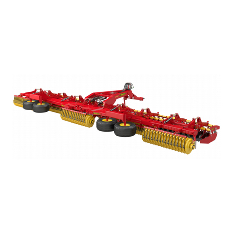
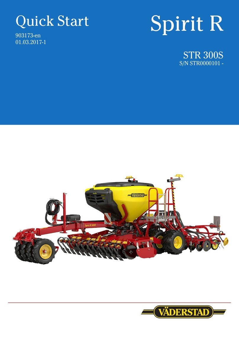
Vaderstad Spirit 600S Series User manual

Quick Start
903174-en
01.03.2017-1
Spirit
Series
600-900S
S/N ST00001740-

This Quickstart does not replace the instruction manual!
Installation of electrics and hydraulics 3
Settings 4
E-Control 11
Setting of wing and centre cradle pressure 21
Attachments
Rotors 22
Seed sowing and fan RPM 22
Uploading new software – iPad 23
Table of contents
This QuickStart does NOT replace the instruction manual that contains much
more detailed information!

3
1. Yellow circuit – The main circuit for lifting, lowering, bout marker arms
and operation of front tool.
2. Black circuit - Circuit for fan operation, drill coulter pressure and following har
row pressure.
3. Red circuit – Wing extending/retracting and operation of CrossBoard.
4. White circuit – Hydraulic support leg (accessory)
4. 3/4” hose - Free return
Circuit Function Requirements
Approx. 50 l/min
approx. 40–30 l/
min with variable
flow.
(Preferably prior-
itised)
approx. 20 l/min
approx. 10 l/min
NOTE: Max. 5 bar
in counterpres-
sure.
01.03.2017
ST 600-900S
1. Electrical installation in tractors
2. Installation of hydraulics
Tractor main
switch
Connect the GateWay cable if the tractor has an ISOBUS terminal.
Lock the terminal using the locking bolt (A).
The tractor’s main power
switch
Installation
If the tractor is not equipped with an ISOBUS switch, tractor cabling is available (Accessories, parts no.
172447).
Use the heavy cables and connect in and after the main power switch.

401.03.2017
ST600-900S
Settings
NOTE: It is possible to make approximate basic settings on a flat, solid floor, but you can only perform final
checks of your settings when sowing in the field!
1. Set the frame to the horizontal
With the tractor connected, the seed drill frame must be absolutely horizontal with the ground.
• If this is not the case, adjust the top rod of the draw bar to bring the machine parallel with the
ground.
2. Radar
The upper edge of the radar securing must be parallel with the ground and
therefore parallel with the frame.
The radar can be re-calibrated if you believe that the speed or area measure-
ment are not correct. Refer to the instruction manual for how to do this.
Upper edge of
the securing is
parallel with the
frame.
Frame parallel
with the ground

501.03.2017
ST 600-900S
3. Set SystemDisc
• It is important to vent all hydraulic cylinders prior to making any adjustment. Refer to the manual
menu on page 10.
• In order to set the centre and wing sections, lower the front tool to approx. 1 cm above the ground.
• Adjust the piston rods of the wing front tool if this is necessary in order to have the wings at centre
level.
Short piston rod Extend the piston
rod
Front tool System Disc
If the front and rear discs have different distances to the ground, adjust the push rods (A) in order to bring
the front and rear discs to the same distance to the ground.
A
Adjust the length of the piston rods (B) if
the CrossBoard does not line up between
the centre and wing sections.
B
Front tool System Disc and CrossBoard Heavy
Settings

601.03.2017
ST600-900S
Track eradicator
If the machine is equipped with CrossBoard and a track eradicator there will
be two control plates by the arm attachments.
When the relationship between CB and SD has been changed, the track eradi-
cators must also be changed in order to achieve the correct angle of attack.
The screws must be set at the same symbol in both of the attachments.
CrossBoard - SystemDisc
The relationship between CrossBoard and SystemDisc can be set to three different values:
• ACrossBoard far up in order to go deeply with SystemDisc.
• B Normal position.
• C CrossBoard far down if you do not want to use SystemDisc.
NOTE: If the machine is equipped with a track eradicator, this must also be rest when the CrossBoard is
adjusted. See next page.
A
B
C

701.03.2017
ST 600-900S
Settings
5. Spill prevention plates
The relationship between SystemDisc
and the spill prevent plates can be ad-
justed. This does not normally need to
be done.
4. Front tool Single CrossBoard Heavy
• It is important to vent all hydraulic cylinders
prior to making any adjustment.
• In order to set the centre and wing sections,
lower the front tool to approx. 1 cm above the
ground.
• Adjust the piston rods of the wing front tool if
this is necessary in order to have the wings at
centre level.
• The work angle of CrossBoard is set using the
turnbuckles (A).
A
6. Linear seed drill unit
• NOTE: Ensure that both of the bout marker arms are deactivated before this operation!!!
• Lift the seed coulters to the top position and here place 3 thick and 3 thin clips on the clips holder axle.
• Ensure that the nut and thread are 35 mm at the centre section (refer to image below).
• Start the fan (to obtain coulter pressure).
• Lower using the Yellow circuit.
• Compare the wing sections with the centre section.
• If adjustment is required, raise the seed coulter in order to relieve the load on the adjustment nut.
35 mm
Tighten the
nut
Untighten the
nut

801.03.2017
ST600-900S
7. Coulter pressure
• In order to have the same coulter pressure in the centre and wing sections the piston rods of
the seed coulters must be lined up.
• The intermediate section is used as a reference in this adjustment. If adjustment is required,
this is done on the piston rods of the wing sections.
• Do the same as on page 16 in order to pressurise the seed coulters.
• NOTE: Ensure that the bout markers are switched off before doing this!!!
• Compare the cylinder mounting hole between the centre and wing sections.
Centre section
If the piston rod mounting holes of the wing sections are lower than the
centre section, shorten the piston rod of the wing sections.
If the piston rod mounting holes of the wing sections are higher than the centre
section, extend the piston rod of the wing sections.

901.03.2017
ST 600-900S
8a. Following harrow - “Heavy” model
The weight of the “heavy” following harrow can be relieved in E-Control, refer to page 17 Hydraulic follow-
ing harrow.
The following harrow can also be adjusted to have different angles of attack with the ground:
Normal position
Light conditions/a lot of straw Hard conditions/no straw
8b. Following harrow - “Light” model
Settings

10 01.03.2017
ST600-900S
8. Scraper
>5 mm
9. Light soil kit (accessory)
Adjust the rubber rods so that they are away from the bank that can form between the repacking wheels on light
soils.

1101.03.2017
ST 600-900S
E-Control
E-Control
Home screen (Drive menu)
4.
6.
Before each season, you should connect your iPad to the Internet and open E-Control to check whether any new
updates have been released. Refer to Attachment 3.
1.
3. 2.
5.
7. 8.
1. Setup, see next page.
2. Drive checks.
3. Half machine shut-off:
4. Manual selection of bout marker arm (Left, Right, Both or None).
5. Tramlining. Refer to the instruction manual for how to change the cycle.
6. Monitoring, seed amount, adjustable feed amount, on and off, fan speed.
6a. Buttons that can select: Deep SystemDisc, Coulter pressure, Area, Area/hour and Speed.
7. Information menu. Alarm history and service menu. Refer to the instruction manual for more information.
8. Wing extending/retracting menu.
6a.

12 01.03.2017
ST600-900S
1. Setup
Press Setup to access:
a. Calibration of Delivered seed
b. Calibration of Radar
c. Basic settings Front tool
d. Basic settings Drilling unit
e. Basic settings Sequence control
Refer to the instruction manual for general settings:
General (Machine basic settings)
Tramlining.
Alarm settings
Basic settings of coulter pressure.
If you access any of the calibration menus, a pop up will appear:
NOTE: Feed output stops if you access any of the calibration menus!
Select Yes
A number of things need to be considered before commencing the calibration:
Refer to Attachment 1 for Choice of rotor and setting drilling depth.
• Which seed box roller is suitable for the crop that is to be sown?
Spirit is supplied with three different rollers for the seed feed housing as standard:
Grain roller (large seed), oil plant roller (small seed) and grass seed roller.
Two different rings are also supplied with the machine for lower feed amounts - A rubber ring for, for exam-
ple, maize and hybrids of rye (approx. 20-70 kg/ha).
One for rapeseed (below approx. 2.0 kg/ha).
• Which gear in the seed feed housing is appropriate?
Generally it is always best to try the low gear in the seed feed housing to begin with.
If the low gear does not provide sufficient seed amount when sowing, there will be an alarm “?? max.
speed”.
- Change to the high gear and re-calibrate!
1a. Calibration of delivered seed
• Is the low level sensor in the correct position?
• Refer to Attachment 1 for other sowing settings.

1301.03.2017
ST 600-900S
E-Control
3. Enter the required seed application rate (
kg/ha)
4. Enter the required increase/decrease of variable
application rate in %.
5. Place the calibration bag on the selected seed feed
housing (refer to image on next page).
6. Select prefilling (1) or press the plus button
on the MiniRemote to fill the feed rollers. The
MiniRemote is located on the left side of the seed
hopper.
5. Empty the trays and return them to the calibra-
tion position.
6. Press Run (2) or the axe button on MiniRemote
to fill the trays with grain.
Pulses are now counted for as long as the button
is pressed in.
7. Pour the seed from the tray into the calibration
bag and weigh the content.
8. Enter the value (3) and the computer will calcu-
late the number of pulses per kilo (4).
It is also possible to manually enter the number of pulses
per kg by selecting Calibration value (4) and then chang-
ing it to the selected value.
1. 2. 3.
4.
Contd. from previous page.
1b. Radar
It is always beneficial to calibrate the radar for an exact report. Refer to the instruction manual.
1. Selection of which side you would like to calibrate
on (Left/Right).
2. If you know that both of the output boxes pro-
duce the same number of pulses per kilo, you can
choose to conduct a calibration on one side. The
value that is entered will then be automatically
saved for both of the sections.

14 01.03.2017
ST600-900S
1c. Basic settings Front tool
- Begin by configuring the scale values for
the front tool.
1. Lower the front tool so that the discs
exactly touch the ground.
Press:
and enter the current scale value.
1.
3.
2.
0.50
Current
scale value.
2. Fully raise the front tool, press:
and enter the current scale value.
3. Measure the distance between the front
tool discs and the ground in centimetres.
Press:
Enter the height to the ground in cm.
Return to the front tool calibration by pressing:

1501.03.2017
ST 600-900S
- The Low-lift position is now
set!
1d. Basic settings Drilling unit
Setting of low-lift position for the drilling unit.
Lift the drilling unit with the yellow circuit to
the desired low-lift height.
- Press Low-lift.
- Enter the current scale value
(10.0).
Current
scale value.
After the configuration has been complet-
ed, the ground level will be equal to 0,
above ground will be minus and below will
be positive (in the example next to this
SystemDisc is therefore approx. 1
cm above the ground).
The activation time indicates
how long the depth setting for SystemDisc
is active in the run menu.
- Lift SystemDisc to the intended low-lift
position.
- Press
- Enter current scale value.
- Lower SystemDisc to the intended work
ing depth.
- Press
- Enter current scale value.
- Finished!
Current scale
value.
E-Control

16 01.03.2017
ST600-900S
1e. Basic Settings Sequence control
With the sequence control active, the whole seed drill does not need to be up on the headland before lift-
ing and when it is lowered the front tool will be lowered first, followed by the seed coulters.
Option to deactivate seed coulters and
front tool so that they stop upon lowering.
- Time from the front tool leaving the low-lift posi-
tion until the drilling unit begins to be lowered.
- Time from the front tool leaving the working
depth until the drilling unit begins to be raised.
- Distance from the front tool leaving the low-lift
position until the drilling unit begins to be low-
ered.
- Distance from the front tool leaving the working
depth until the drilling unit begins to be raised.
Both time and distance are used, and it is the one that is first reached that activates the sequence.
For example, if you reverse out into a corner in order to begin sowing, it is therefore time that starts the sequence.
For the above setting it would therefore be:
The drilling unit begins to be lowered 0.5 m
or 0.5 seconds after lowering commences.
When lowering
When raising The drilling unit begins to be raised 1 m or
1 second after raising commences.

1701.03.2017
ST 600-900S
2. Then press on the plus or mi-
nus sign a number of times until
the required pressure for the
following harrow is reached.
- As a guide a value of 20 can
correspond to the tare weight.
1 is maximum relieved and 0 is
fulfilled.
- If you want the following har-
row to remain raised all the time
you are driving, go to the basic
settings menu and set Following
harrow type to Off.
Headland Furrow
1. Select the symbol for headland or furrow. It will then be marked in green.
C. Hydraulic following harrow
Press the button to access an adjustment menu for the following harrow.
This menu allows you to have different following harrow pressures for headland and furrows.
2. Drive checks
A. Manual feed output.
If you want to start feed output from a stationary position, e.g. in a corner, or during output verification,
press and hold the button marked in green.
Preselect the speed in the Basic settings menu.
B. Lift stop.
For retracting the bout marker arms without lifting the machine, e.g. around wells or posts.
Press the button and use the lifting ram to pull in the bout marker arms.
When you have passed the obstacle, use the lifting ram to extend the bout marker arms again.
Press the button again otherwise it will return to its switched off position after 30 seconds.
The button remains green as long as this is activated.
A.
B.
C.
E.
F.
G.
D. H.
E-Control

18 01.03.2017
ST600-900S
F. Low-lift
The button lights green when low-lift is activated.
Deactivate low-lift if the following furrow needs raising, e.g. for reversing.
Low-lift active.
Tramlining active. Tramlining
stopped.
G. Tramlining
Automatic progression of tramlining program and bout takes place when the button is white.
Press the button (it will then become green) when you wish to prevent progression.
H. Seed coulter pressure
Note: The fan must be started!
- Select the symbol for the coulter pressure in
the monitoring display.
- Increase or decrease the coulter pressure
using the buttons.
Current coulter
pressure
Current control value
E. Automatic bout marker switching
The symbol is green when automatic bout marker switching is activated.
The symbol above shows which bout marker arm is activated.
D. Depth setting for SystemDisc
Two of the buttons in the monitoring display are optional:
- Choose to display the symbol for the current depth front tool.
- Press (D in Drive checks).
- Raise or lower using the lifting circuit (Yellow circuit).
- Press in order to deactivate the option. It will then
be deactivated after the set activation time (refer to 1 c Basic
settings Front tool).
Current cultivation
depth.

1901.03.2017
ST 600-900S
6. Monitoring of seed
Press the axe button to temporarily switch
off the feed output. The button will then
be greyed out and STOP will appear in the
display.
5. Tramlining cycle
The green tractor pattern is
displayed when tramlining
is taking place.
Selected tramlining program (36
m on a 6 m in this case).
Actual driven pass in the
tramlining cycle.
Refer to the instruction manual for how
to change the tramlining program and
the track width.
Select actual sown amount, and a pop up will appear, make changes using the drop-down list depending on
whether you want to increase or decrease the sown amount, then press Done.
Select actual sown amount again, and then Reset to return to the original sown amount.
6. Adjustment of the sown amount
E-Control

20 01.03.2017
ST600-900S
When the front tool and the drilling unit are in the extended position the following menu will be displayed:
Do what is shown on the screen, extend or retract the machine in or out using the red circuit.
NOTE: Continue to extend for approx. 10-
15 seconds after the wings have come out
in order to pressurise the system.
When extending:
Exit the wing extending/retracting menu by
pressing the Home Screen, lift the machine
using the yellow circuit and keep it there
for approx. 10 seconds in order to line up
the seed drill unit and the front tool.
When retracting:
Exit the wing extending/retracting menu
by pressing the Home Screen, lift the seed
drill unit and front tool to transport height
using the Yellow circuit.
8. Wing extending/retracting
Press Wing extending/retracting in the Run menu.
Press Start.
Do what is shown on the screen, lower or raise using the lifting circuit (yellow circuit).
This manual suits for next models
2
Table of contents
Other Vaderstad Farm Equipment manuals
Vaderstad
Vaderstad Rapid Series User manual

Vaderstad
Vaderstad CR 425-825 Series User manual

Vaderstad
Vaderstad Cultus Series User manual

Vaderstad
Vaderstad Spirit StripDrill ST 600C Series User manual

Vaderstad
Vaderstad Rexius Twin Series User manual

Vaderstad
Vaderstad Carrier CRL 1225 Series User manual

Vaderstad
Vaderstad TopDown TD 300 Series User manual

Vaderstad
Vaderstad E-Services TPF Series User manual
Vaderstad
Vaderstad Carrier 420 User manual

Vaderstad
Vaderstad NZ Aggressive NZA 600 Series User manual