3L-1763-H
==================================================================================================
English Manual
COMPATIBILITY
For use with lawn tractors, garden
tractors, ztr’s, and riding mowers. See
the safety section for towing vehicle
requirements.
Continues on page 4
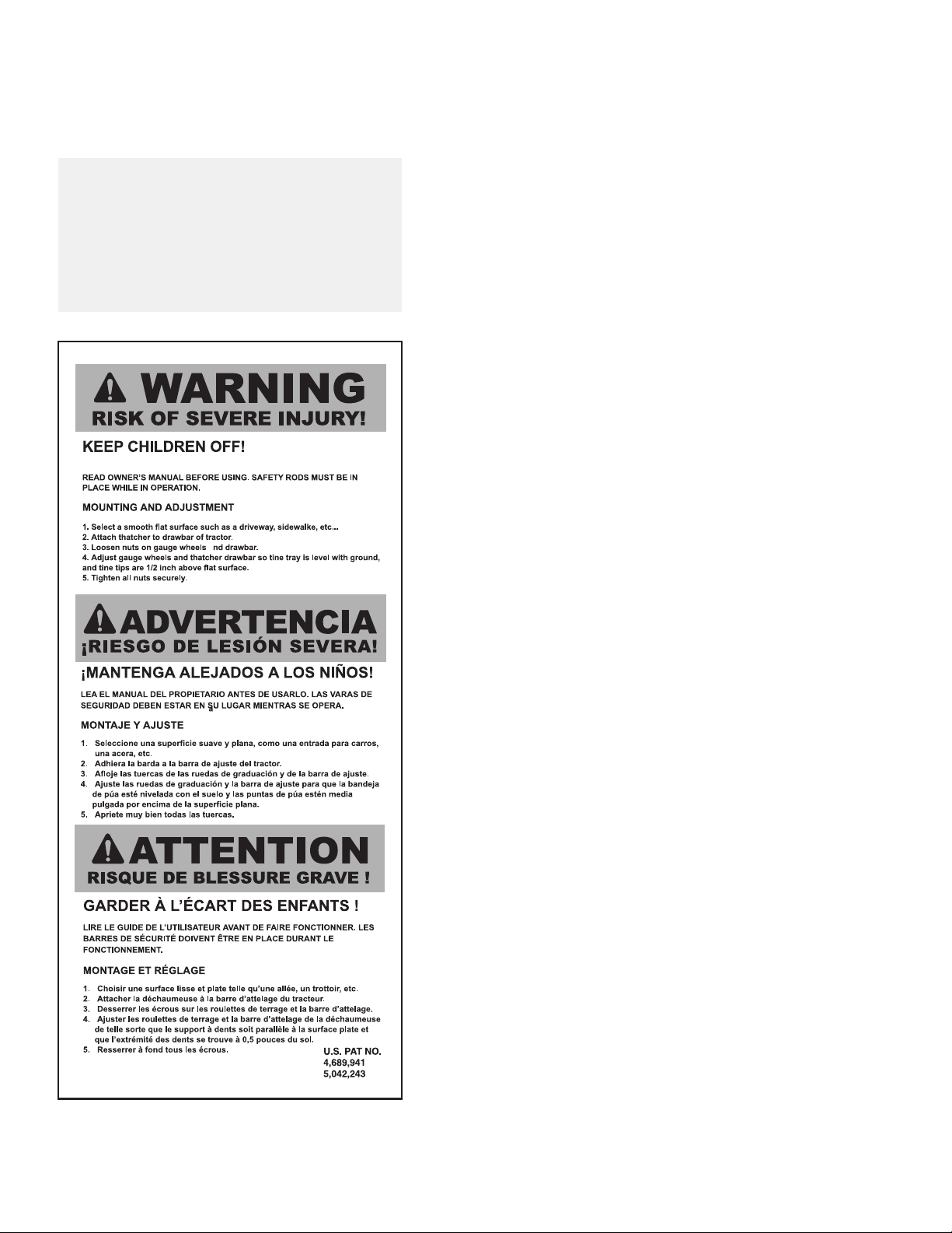
SAFETY
Caution should be taken when towing and/or using any
attachment. This attachment combined with the weight distribu-
tion, turning radius, and speed of towing vehicle can result in
severe injury or death to operator, damage to towing vehicle,
and/or attachment if not used properly. Follow all towing safety
precautions noted in the towing vehicle owner’s manual, includ-
ing the following precautions:
• Ensure the combined weight of the towing vehicle (tow vehicle
weight + operator weight) is greater than the maximum towed
weight of attachment (empty attachment weight + weight of load).
• Do not exceed maximum towing capacity of towing vehicle.
• Do not exceed the maximum drawbar pull rating of the towing
vehicle. Drawbar pull is the horizontal force required to pull the
attachment (including weight of load).
• Only tow this product in the vehicle’s tow mode/speed setting or
less than 5 mph. Do not exceed 5 mph.
• Towing speed should always be slow enough to maintain control.
Travel slowly and use caution when traveling over rough terrain.
Avoid holes, rocks and roots.
• Slow down before you turn and do not turn sharply.
• Use wide turning angles to ensure the attachment follows the
path of the towing vehicle.
• Do not use attachment on steep slopes. A heavy load could cause
loss of control or overturn attachment and towing vehicle. Addi-
tional weights may need to be added to your vehicle; check with
towing vehicle manufacturer for recommendations.
• Reduce towed weight when operating on slopes.
• Keep all movement on slopes slow and gradual. Do not make
sudden changes in speed, directions, or turning.
• If you start and stop suddenly on hills, you may lose steering con-
trol or the towing vehicle may tip. Do not start or stop suddenly
when going uphill or downhill. Avoid uphill starts.
• Slow down and use extra care on hillsides. Turf conditions can
affect vehicle stability. Use extreme caution while operating near
drop-offs.
• Do not drive close to creeks, ditches and public highways.
• Watch out for trafc when crossing near roadways.
• Use care when loading or unloading the vehicle into a trailer or truck.
• The attachment can obstruct the view to the rear. Use extra care
when operating in reverse.
• When reversing, carefully back-up straight to avoid jackkning.
Do not allow towing vehicle wheels to contact attachment draw
bar. Damage could result.
• Stop on level ground, disengage drives, set the parking brake,
and shut off engine before leaving the operator’s position for any
reason including emptying the attachment.
GENERAL NOTES (Operation)