TimberPro TL775 Series Manual

TL/TN 775 MachiNe iNiTiaL SeT-UpGUide
Manufactured To Get
Your Job Done
Manufactured To Get
Your Job Done
By the Most Trusted and Versatile
Company in the Industry
By the Most Trusted and Versatile
Company in the Industry
2021 MY2021 MY
L9 Cummins EnginE
TrusTEd mosT ByThE ForEsTry indusTry
L9 Cummins EnginE
TrusTEd mosT ByThE ForEsTry indusTry
TL/TN 775 MachiNe iNiTiaL SeT-UpGUideTL/TN 775 MachiNe iNiTiaL SeT-UpGUide

PAGE INTENTIONALLY LEFT BLANK
L9 Cummins EnginE
TrusTEd mosT ByThE ForEsTry indusTry
L9 Cummins EnginE
TrusTEd mosT ByThE ForEsTry indusTry

P A1 of A3 P A2 of A3
TL/TN-775 MAchiNe iNiTiAL SeT-UPGUide
MachiNe SeT-UpOrder per MachiNe cONfiGUraTiON Type
The set-up instructions in this manual are created for all machine congurations.Depending on your purchased machine
conguration, the order of this set-up procedure may not be correct for your machine. Follow the Machine Set-up Order
outlined below to adequately set-up your machine conguration.
NOTE:
There are a variety of adjustment procedures outlined throughout this manual. These settings may only need to be adjusted
if the part is not calibrated to operator's preference or if there is an issue.
FELLER BUNCHER SET-UP ORDER
1. Setting Load Sense / Stand-By on Implement Pump (Section 1)
2. Setting Implement Pump POR / High-Side Pressure (Section 1)
3. Setting Charge Pressure (Section 4)
4. Hydraulic Fan Motor Set-up / Setting Fan Speed (Section 5)
5. Setting Valve LS Relief (Section 6)
6. Main Control Valve Set-Up - M4-15 Small Section (Section 6)
7. Setting Swing Pressure and Setting up the Swing Pump (Section 7)
8. Setting the Track Drive Pressures (Section 8)
9. Disc Saw Pump Set-up (Section 9)
SHOVEL/LOG LOADER SET-UP ORDER
1. Setting LS (Load Sense) / Stand-By on Implement Pump (Section 1)
and Auxiliary Pump (Section 2)
2. Setting Charge Pressure (Section 4)
3. Setting Implement Pump POR/High-Side Pressure (Section 1) and Auxil-
iary Pump POR/High-Side Pressure (Section 3)
4. Hydraulic Fan Motor Set-up / Setting Fan Speed (Section 5)
5. Setting Valve LS Relief (Section 6)
6. Main Control Valve Set-Up - M4-15 Small Section (Section 6)
7. Setting Swing Pressure and Setting up the Swing Pump (Section 7)
8. Setting the Track Drive Pressures (Section 8)
PROCESSOR SET-UP ORDER
1. Setting LS (Load Sense) / Stand-By on Implement Pump (Sec-
tion 1) and Auxiliary Pump (Section 2)
2. Setting Charge Pressure (Section 4)
3. Setting Implement Pump POR / High-Side Pressure (Section 1)
and Auxiliary Pump POR / High-Side Pressure (Section 4)
4. Hydraulic Fan Motor Set-up / Setting Fan Speed (Section 5)
5. Setting Valve LS Relief (Section 6)
6. Main Control Valve Set-Up - M4-15 Small Section (Section 6)
7. Setting Swing Pressure and Setting up the Swing Pump (Sec-
tion 7)
8. Setting the Track Drive Pressures (Section 8)
ADDITIONAL ITEMS TO CHECK
• Adjusting Port Relief (Section 10)
• Changing Min. Displacement (Section 11)
• Setting Shift Points (Section 12)

P A1 of A3 P A2 of A3P A2 of A3 P A3 of A3
TL/TN-775 MAchiNe iNiTiAL SeT-UPGUide
TiMber prO recOMMeNded preSSUreS fOr 765/775
IMPORTANT
All pressures are set with the machine running at minimum of 1500rpm except for Swing Pressure. Swing pressure is set to
2050rpm.
COMPONENT PRESSURE (PSI)
Implement Pump LS 350 - 600
Charge Pump 425
Implement Valve LS Relief 4200
Main, Tool, and Stick are set with the Valve LS Relief 4200
Implement Pump POR 4600
Swing Pump POR 5200
Swing Pump Main Reliefs 5800
Track Drive Pump POR 5500
Track Drive Pump Main Reliefs 6000
NOTE
• Set LS with LS line removed and plugged and Pump open to Atmosphere.
• Main, tool, stick, level, and M7-22 portion of valve are ALL set by the main valve LS Relief
• Minor Function, Clamp, Accumulator, and Rotate leave Timber Pro at 3600 psi or to the head manufacturer recommenda-
tions
GeNeraL KNOwLedGe
• AC system holds 4lbs of R134
• All gear lube in machine requires 75W90 Synthetic except nal drives require CAT50
• Hydraulic oil is ISO46
P A2 of A3 P A3 of A3
TL/TN-775 MAchiNe iNiTiAL SeT-UPGUide
TL/TN-775 MachiNe iNiTiaL SeT-Up
A series of individual set-up procedures need to be performed to properly set-up the machine for use and/or personal
preference. The following items need to be performed to properly set-up your machine.
• Rexroth Implement Pump, Valve Set-up
• Auxiliary Pump Set-up
• Hydraulic Fan motor Set-up
• Disc Saw Pump Set-up
• Track Drive Pressure Setting
• Shift Point, Beginning of Regulation Setting
• Swing Pump Pressure Setting
• Charge Pressure Setting
• Changing Min. Displacement Setting
priOr TO perfOrMiNG The abOve LiSTed prOcedUreS
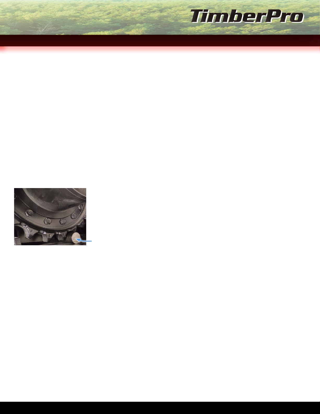
FIGURE 1, PIN INSTALLED
AT TRACK FINAL DRIVE
1. Install pin at track nal drive to stall the machine for maintenance. See Figure 1.
2. Warm the machine hydraulics to operating temperature of 140 F 60 C.
3. Warm engine coolant temperature to operating temperature.
IMPORTANT
• FOR PRESSURE CHECKS A 10,000 PSI DIGITAL PRESSURE GAUGE IS RECOMMENDED.
• FOR STAND-BY PRESSURE CHECKS A 600 PSI GAUGE IS CALLED FOR IN MANUAL, BUT PRESSURES COULD SPIKE IF CORRECT
SEQUENCE IS NOT FOLLOWED, DAMAGING THE GAUGE. IF A DIGITAL GAUGE IS USED, DAMAGE COULD BE PREVENTED.
• UTILIZE MODEL SPECIFIC MACHINE SET-UP CHECK SHEET FOR SPECIFIED PRESSURES.
reqUired TOOLS
• Tachometer • Standard Combination Wrenches, Assorted 3/8 in. - 1-3/8 in.
• Metric Combination Wrenches, Assorted 9 mm - 35 mm
• Standard Allen Wrenches, Assorted 5/32 in. & 1/4 in.
• Metric Allen Wrenches, Assorted 3 - 5 mm & 8 mm
• Pressure Gauge Various Sizes
• 0 - 600 psi 0 - 5 Mpa
• 0 - 6000 psi 0 - 50 Mpa
• 0 - 10,000 psi 0 - 8 Mpa
NOTE:
• A 10,000 psi Digital Gauge can be used in leu of Pressure Gauges listed above.
Pin installed at Track Final
Drive
P PB of 17 P 1 of 17
iMpLeMeNT pUMp, MaiN cONTrOL vaLve SeT-Up
IMPLEMENT PUMP/R9 LARGE SECTION, MAIN CONTROL VALVE SET-UP
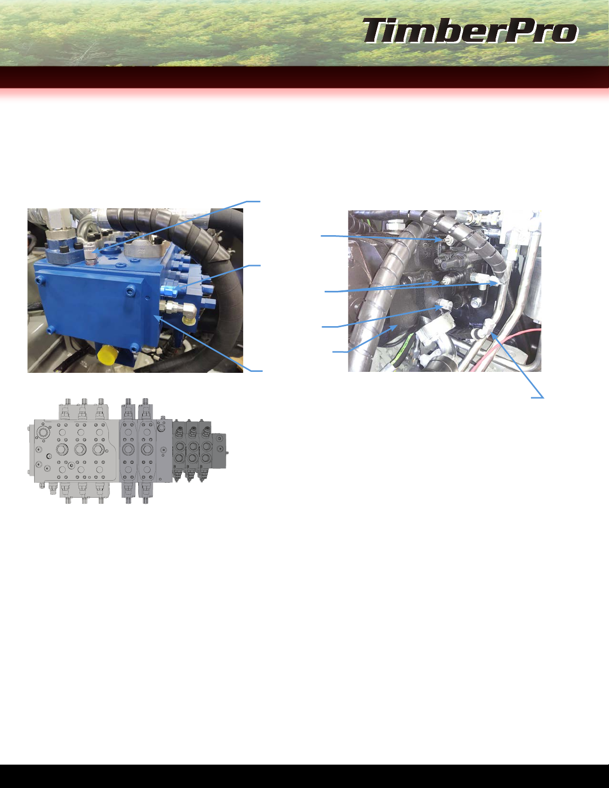
1. Turn the LS (Load Sense) relief valve inward gently until it bottoms out. The reief valve is located on the main control
valve (Figure 1) . Once the relief valve bottoms out, back out ¼ turn.
R9 Section
MLS 1 Module Load
Sense Gauge Port
POR (Pressure
Over Relief) Port
LS (Load Sense)
Line
LS Gauge Port
Implement Pump
LS Relief Valve
FIGURE 1, MAIN CONTROL VALVE FIGURE 2, IMPLEMENT PUMP
LS Line shown removed and capped.
NOTE
Main Control Valve section quantities vary
depending on machine’s purpose and customer
spec’d options.
FIGURE 3, MAIN CONTROL VALVE SECTION TYPES
R9 Section M7-22 M4-15
2. Remove the LS line from the implement pump. See Figure 2 above.
3. Start the machine and install the pressure gauge on the implement pump gauge port.
4. Run the machine at 1500rpm.
5. Adjust the LS pressure to the appropriate setting spec’d on the Recommended Pressures at the beginning of this procedure.
6. Turn off the machine and re-install the LS line removed in Step 2.
7. Set the correct pressure by using the POR (Pressure-Over-Relief) adjustment port on the implement pump. See Figure 2 above for
POR adjustment port.
8. Set valve LS (Load Sense) back to working pressure.
IMPORTANT
IF THE MACHINE HAS AN AUXILIARY PUMP, THE SATURATION CIRCUIT WILL NEED TO BE BROKEN BY REMOVING THE LS LINE FROM
THE PUMP AND CAPPING THE HOSE. See Figure 2 above.
IMPLEMENT PUMP/R9 LARGE SECTION, MAIN CONTROL VALVE SET-UP PROCEDURE END
TL/TN-775 MAchiNe iNiTiAL SeT-UPGUideSecTioN 1
P 2 of 17 P 3 of 17
TL/TN-775 MAchiNe iNiTiAL SeT-UPGUide
aUxiLiary pUMp SeT-Up
IMPORTANT
ALWAYS USE THE SAME GAUGE TO SET BOTH THE MAIN IMPLEMENT PUMP AND AUXILIARY PUMP.
1. Check the provided Recommended Pressures at the beginning of the procedure and note the settings for the implement
pump Stand-by Pressure and the implement pump POR (Pressure-Over-Relief) Pressure.
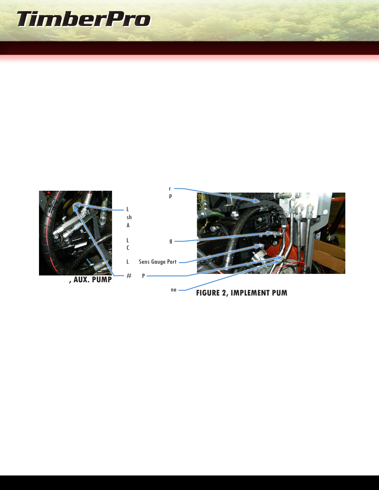
2. Remove the LS (Load Sense) Jumper line from the Auxiliary Pump and cap the hose with a #6 cap. See Figure 1 and/or
Figure 2 below.
IMPORTANT
DO NOT CAP THE 90° FITTING FROM THE AUX. PUMP PORT. IT IS IMPORTANT TO LEAVE THE PUMP OPEN TO BREATH.
FIGURE 2, IMPLEMENT PUMP LOAD SENSE
CONNECTION
Load Sense Jumper
at Implement Pump
Load Sense Jumper
shown removed from
Aux. Pump
Load Sense Existing
Connection at Tee
Load Sens Gauge Port
#6 CAP
Load Sense Hose Line
Shown removed from
Imp. Pump
FIGURE 1, AUX. PUMP
LS CONNECTIONS
3. Start the machine and run at 1500rpm.
SETTING AUXILIARY PUMP STAND-BY PRESSURE
1. Install the gauge on the auxiliary pump gauge port and check pressure. Set the pump Stand-by Pressure to 25 psi lower
than the implement pump pressure setting that was gathered in Step 1 above. See Figure 2 for the auxiliary pump
gauge port location.
EXAMPLE
If the implement pump Stand-by Pressure is 350 psi, set the Auxiliary Pump Pressure to 325 psi.
2. Install the LS Line on the main control valve (Figure 3) and connect directly to the auxiliary pump LS Port (Figure 4).
3. Run the engine at 1500rpm.
3a. Bottom out the stick boom.
3b. Adjust pressure if needed.
4. Start the machine and install the gauge on the implement pump LS gauge port. See Figure 2 on previous page for LS
gauge port location.
SecTioN 2

P 2 of 17 P 3 of 17
4a. Run the machine at 1500rpm.
4b. Have the machine operator bottom out the stick boom.
4c. Set the correct pressure by using the POR (Pressure-Over-Relief) adjustment port on the implement pump. See
Figure 2 on previous page for POR adjustment port.
AUXILIARY PUMP SET-UP PROCEDURE END
SeTTiNG aUxiLiary pUMp pOr / hiGh-Side preSSUre
1. Set the auxiliary pump POR (Pressure-Over-Relief) / High-side to the same psi that the implement pump POR Pressure
was set to in Step 1 of the Auxiliary Pump Set-up Procedure. See Figure 2 for POR/High-Side port location on the
auxiliary pump.
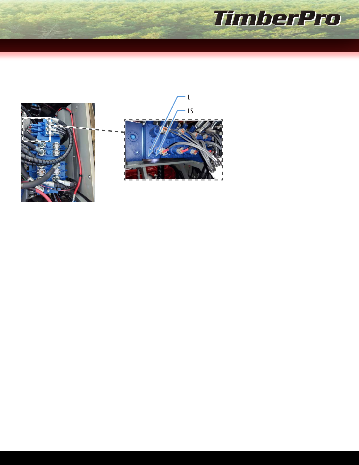
2. On the main control valve, turn the LS Relief in gently until it bottoms out. See Figure 1 below.
3. Install the LS Line that was disconnected earlier on to the auxiliary pump. See Figure 2 below for port location.
4. Set pressure to the setting spec’d on Page A3 of this procedure.
5. Install the gauge used earlier on the LS gauge port located on the main control valve to set the pressure. See Figure 1
below.
6. Run the engine at 1500rpm.
7. Bottom out the stick boom.
8. Set the main control valve LS Relief to the pressure spec’d on the provided Recommended Pressures at the beginning of
the procedure.
9. Set the LS Relief valve back to operating pressure spec'd at the beginning of this procedure.
LS Gauge Port
LS Relief
LS Hose/Line and Port
Location at Aux. Pump
LS/Stand-By
POR/High-Side
Gauge Port
LS Line at Main Control
Valve
FIGURE 1, MAIN CONTROL
VALVE END FIGURE 2, AUXILIARY PUMP
AUXILIARY PUMP POR/HIGH-SIDE PRESSURE PROCEDURE END
TL/TN-775 MAchiNe iNiTiAL SeT-UPGUideSecTioN 2 &SecTioN 3
P 4 of 17 P 5 of 17
TL/TN-775 MAchiNe iNiTiAL SeT-UPGUide
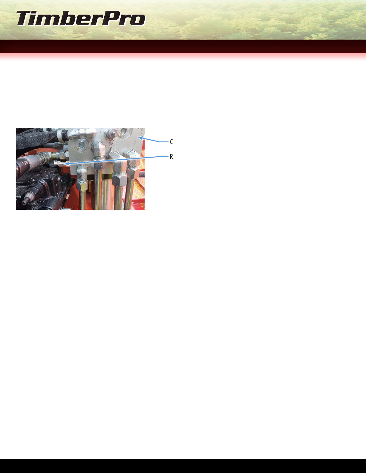
SeTTiNG charGe preSSUre
1. Start the engine and run at 1500rpm.
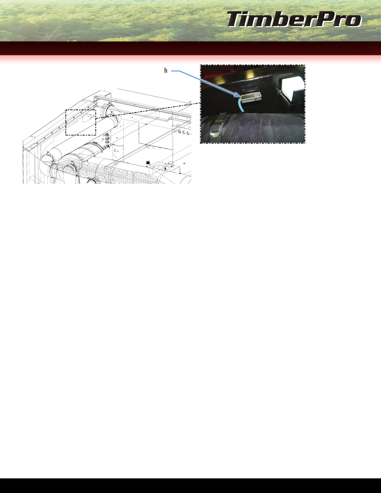
2. Once the machine is running, install a 600 psi gauge on the charge cooler gauge port location shown below. See Figure 1
below.
NOTE
Charge pressure should not deviate more than 25 psi up or down when setting adjustment. Setting pressure at 425 psi
provides the correct ow for the internal orices for ushing the hydrostatic pump controls.
3. If adjustment is needed, turn the SQ1 Cartridge clockwise to increase pressure and counter-clockwise to decrease. See
Figure 1 for SQ1 Cartridge location.
NOTE
Charge manifold may vary per machine model.
SQ1 Cartridge
Gauge Port
Charge Cooler
FIGURE 1, CHARGE MANIFOLD
SETTING CHARGE PRESSURE PROCEDURE END
hydraULic faN MOTOr SeT-Up
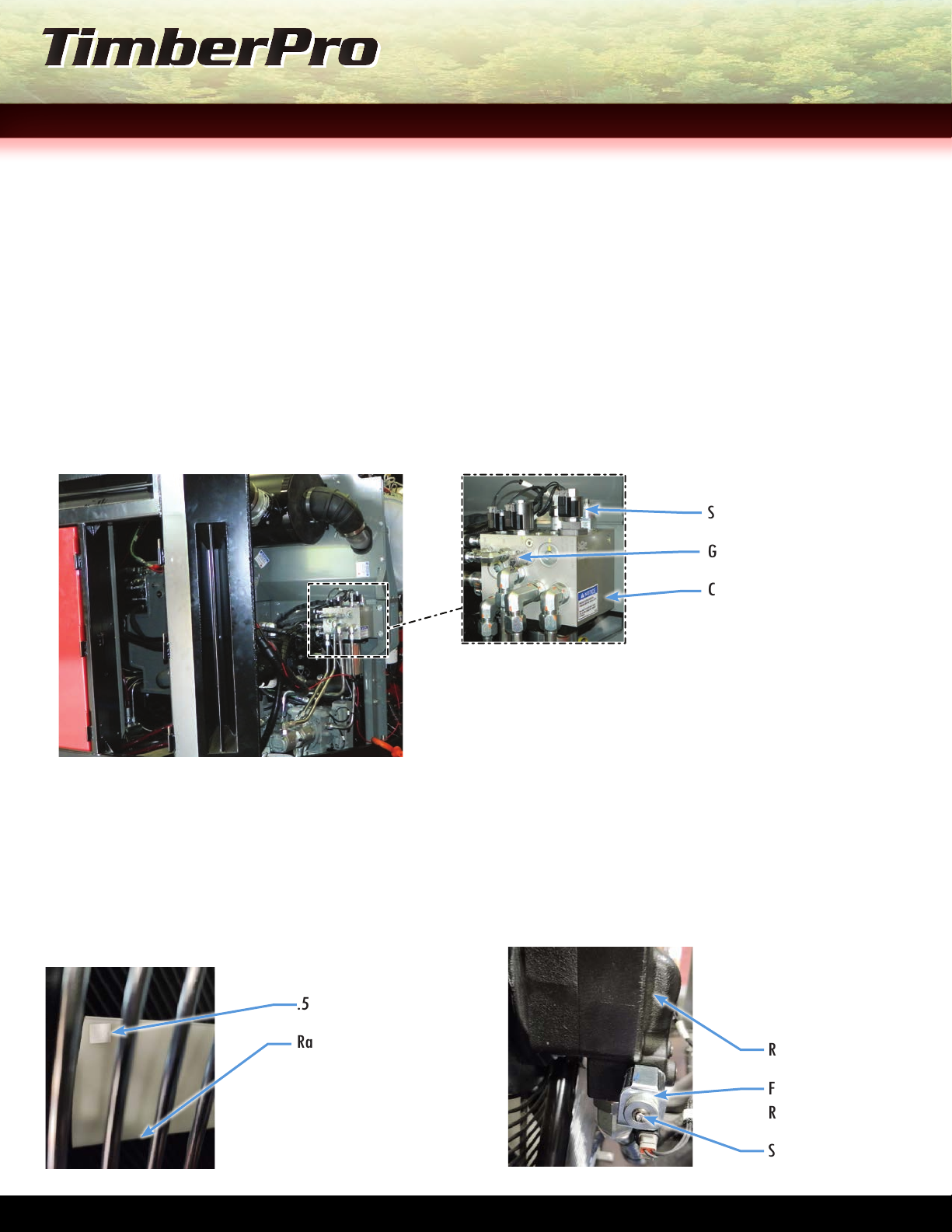
1. Install an approximately 1/2” square piece of reective tape on one of the radiator fan blades as shown on Figure 1
below.
.5" Reective Tape
Radiator Fan Blade
FIGURE 1, RADIATOR FAN BLADE TAPE LOCATION
Radiator Fan Motor
Fan Motor Relief
Relay
Safety Screw
FIGURE 2, RADIATOR FAN
MOTOR SAFETY SCREW LOCATION
2. Remove the Safety Screw installed on the Fan Motor Relief Relay. See Figure 2 on previous page.
SecTioN 4 & SecTioN 5
P 4 of 17 P 5 of 17
3. Once the screw has been removed, start the machine.
IMPORTANT
DO NOT UNPLUG THE COIL ON THE FAN TO GET FULL SPEED. DAMAGE TO THE CHARGE PUMP COULD OCCUR.
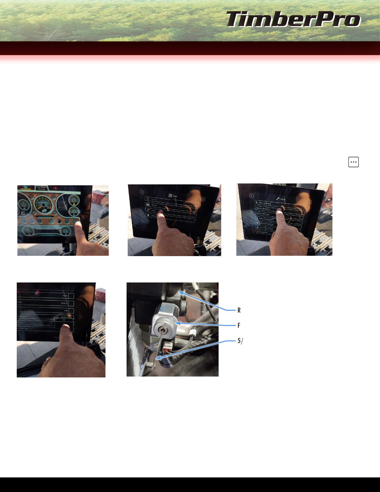
4. Using the IQAN touch screen located in operator cab, turn the fans to FULL ON. Follow the touch screen prompts on the
next page to set the function.
4a. Go to the IQAN touch main screen, select MENU on the main screen. See Figure 3 below.
4b. Once in the Menu screen, select the ADJUST prompt.
4c. On the Adjust screen, select OPERATOR ADJUSTMENTS
4d. The next screen will take you to the FANS FULL ON/OFF menu option. On the right side of the screen select the
. . .
function. Then select the ON function.
FIGURE 3, IQAN MENU OPTION
STEP 4b, ADJUST OPTION
STEP 4c, OPERATOR
ADJUSTMENTS OPTION
STEP 4d, FANS FULL ON/OFF
MENU FUNCTION
Radiator Fan Motor
Fan Motor Relief Relay
5/32” Allen Wrench
FIGURE 4, FAN MOTOR RELIEF
RELAY ADJUSTMENT
5. Run the machine at full engine rpm.
6. Using a photo laser tachometer, check the fan speed by pointing the tachometer laser on the reective tape installed on
the fan blade earlier.
6a. Document speed and save for later.
7. Using a 5/32” allen wrench, turn the Fan Motor Relief Adjustment Relay counter-clockwise for slower fan speed or
TL/TN-775 MAchiNe iNiTiAL SeT-UPGUideSecTioN 5
P 6 of 17 P 7 of 17
TL/TN-775 MAchiNe iNiTiAL SeT-UPGUide
clockwise for faster fan speed. See Figure 4 on previous page.
8. Set the fan speed to 1600 - 1650rpm. If the speed can’t be reached, try turning the RV2 in on the Charge Manifold Block
to adjust the fan speed. See Figure 5 below.
IMPORTANT
OPTIMAL SPEED FOR THE FAN IS 1600 - 1650RPM WITH THE FAN TURNED ON AND THE ENGINE AT FULL RPM.
Charge Manifold Block
RV2 Adjustment Valve
FIGURE 5, RV2 ADJUSTMENT,
CHARGE MANIFOLD BLOCK
9. Once the machine has reached the proper speed, using the RV2 Adjustment Valve and photo laser tachometer, adjust
the valve until you reach a tachometer reading that is 5 - 10rpm’s below your original reading. This will ensure that the
relief is set correctly and the ramping will function properly.
10. Install the gauge used earlier into the MLS 1 (Module Load Sense) port on the main control valve. See Figure 1 on
Page 1 for MLS 1 port location. Bottom out the stick boom and set to the correct pressure spec’d on the Recommended
Pressures at the beginning of this procedure by adjusting on the LS relief valve on the main control valve. See Figure 1
on Page 1 for LS relief valve location.
HYDRAULIC FAN MOTOR SET-UP PROCEDURE END
MaiN cONTrOL vaLve SeT-Up- M4-15 SMaLL SecTiON
An LS Relief for PORT A and PORT B is installed on all M4-15 lower valve sections. See Figure 1 on the next page. Find the
correct pressure for each relief port valve by following the provided Recommended Pressures at the beginning of this
procedure.
NOTE
The Leveling Reliefs are non-adjustable.
1. Start the engine, install the gauge into the MLS 1 Gauge Port on the main control valve. See Figure 1 on Page 1 for
location.
1a. Run the engine at 1500rpm.
SecTioN 5 &SecTioN 6
P 6 of 17 P 7 of 17
1b. Have the machine operator run the function to be set.
1c. Adjust the LS Reliefs on the current main control valve section to change the settings. See Figure 1 below for LS
Relief Valve.
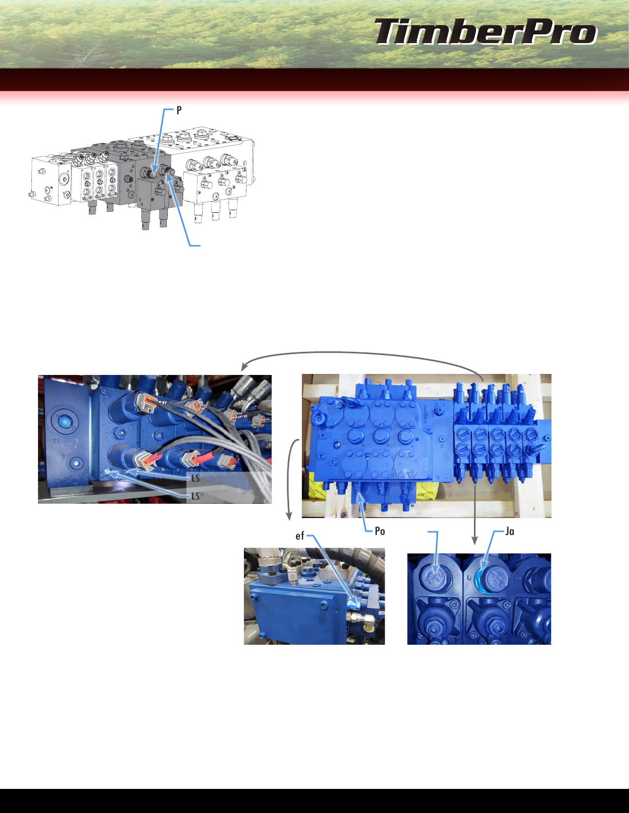
FIGURE 1, MAIN CONTROL
VALVE M4 SECTION SET-UP
LS Relief, PORT A
LS Relief PORT B
ADJUSTING THE PORT RELIEFS ON THE M4-15 SMALL SECTION, MAIN CONTROL VALVE
All M4-15 port reliefs are adjustable on the Rexroth main control valve except the leveling reliefs.
2. Bottom out the function to be set. Read gauge and set A or B port to the pressure needed.
IMPORTANT
DO NOT OVERTIGHTEN THE VALVE.
MAIN CONTROL VALVE SET-UP - M4-15 SMALL SECTION PROCEDURE END
SeTTiNG SwiNG preSSUre
REQUIRED TOOLS
• 6000 psi Gauge
• 4mm Allen Wrench
• 5mm Allen Wrench
• 13mm Allen Wrench
• 18mm Wrench
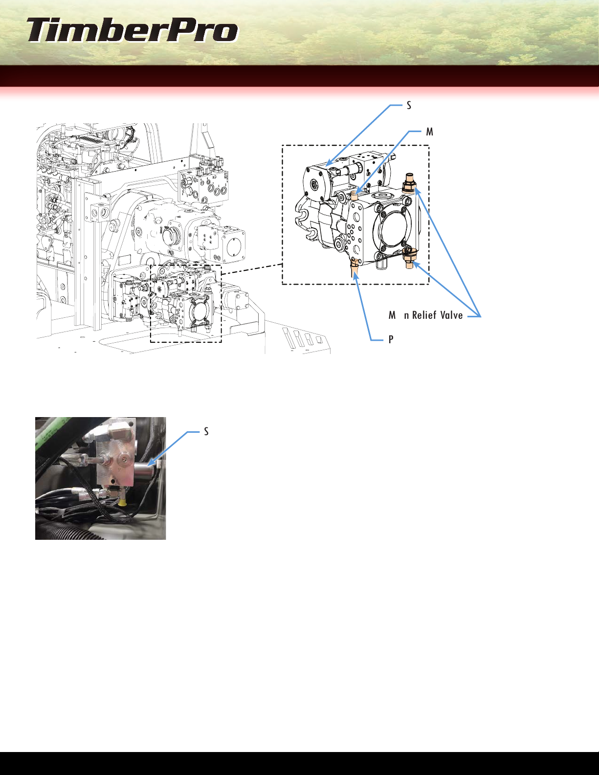
1. Install gauge in the MH Port on the Swing Pump. See Figure 1 on the next page.
TL/TN-775 MAchiNe iNiTiAL SeT-UPGUideSecTioN 6 &SecTioN 7
P 8 of 17 P 9 of 17
TL/TN-775 MAchiNe iNiTiAL SeT-UPGUide
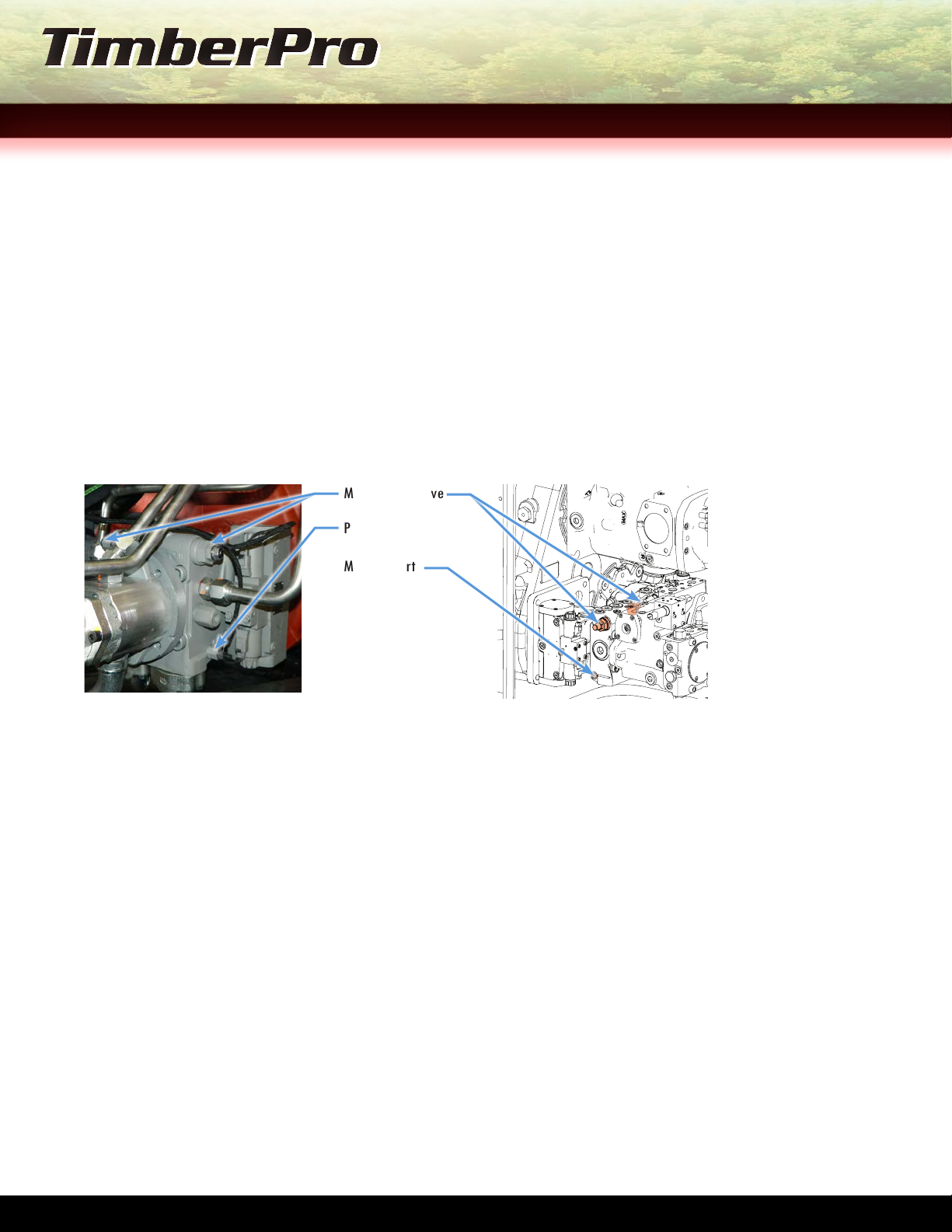
FIGURE 1, SWING PUMP PORT AND VALVE
Main Relief Valve
POR Pressure Over Relief
MH Port
Swing Pump
2. Remove the Swing Brake Coil. See Figure 2 below.
Swing Brake Coil
FIGURE 2, SWING BRAKE COIL
3. On the swing pump, turn the POR Pressure Valve counterclockwise gently until it bottoms out. See Figure 1 above.
3a. Once bottomed out, turn clockwise 1/4 turn to back the system out.
IMPORTANT
GULLWING SWITCH MUST BE BYPASSED TO SET SWING PRESSURE. A WASHER OR ANY SUITABLE METAL OBJECT CAN BE USED TO
BYPASS THE SWITCH. SEE FIGURE 3 ON THE NEXT PAGE FOR SWITCH LOCATION.
MACHINE MUST BE RUN AT FULL ENGINE RPM, 2050, AND FULL mA ON THE IQAN CONTROL.
SecTioN 7
P 8 of 17 P 9 of 17
FIGURE 3, GULLWING SWITCH
Gullwing Switch
4. Start the engine and run at full rpm and mA (milliAmp).
4a. Push boom into ground and swing in one direction.
4b. Note the pressure on the gauge. Pressure reading will be the Main Relief setting.
ADJUSTING THE MAIN RELIEF SETTING:
To adjust the swing pump pressure, turn each swing pump Main Relief Valve either clockwise to raise the pressure or counter-
clockwise to lower the pressure. See Figure 1 on previous page for valve location.
5. Once the pressure is set for the rst Main Relief Valve, with the boom still pushed into the ground, swing in opposite
direction.
5a. Note the pressure on the gauge, and adjust as necessary following the same procedure as the previous steps.
ADJUSTING THE POR PRESSURE SETTING
6. Turn the Swing Pump POR Valve clockwise to raise the pressure or turn counter-clockwise to lower the pressure. See
Figure 1 on previous page for valve location.
NOTE
Unlike setting the Main Control Valve in the earlier steps, it is necessary to swing the boom in only one direction when
setting POR pressure setting.
7. Note the pressure on the gauge, and adjust as necessary by following the previous steps.
IMPORTANT
THE POR PRESSURE SHOULD ALWAYS BE 500 PSI LOWER THAN THE MAIN RELIEF PRESSURE SETTINGS.
8. Once the Main Relief and POR Relief settings are properly adjusted, reinstall the swing brake coil removed at the
beginning of this procedure.
SETTING SWING PRESSURE PROCEDURE END
TL/TN-775 MAchiNe iNiTiAL SeT-UPGUideSecTioN 7
P 10 of 17 P 11 of 17
TL/TN-775 MAchiNe iNiTiAL SeT-UPGUide
SeTTiNG The TracK drive preSSUreS
NOTE:
Rear track pump is designated for LEFT track and Forward track pump is designated for RIGHT track.
SETTING THE POR (PRESSURE-OVER-RELIEF) / HIGH-SIDE PRESSURE
1. Install pin at track nal drive to ensure safety while performing pressure settings on machine. See Figure 1 on Page A3
for pin installed location on track.
WARNING
NOT INSTALLING AN APPROPRIATELY SIZED PIN AT THE FINAL DRIVE COULD CAUSE SERIES DAMAGE TO THE MACHINE AND
CAUSE INJURY TO PERSONNEL.
Main Relief Valve
POR/High-Side
MH Test Port
FIGURE 1, TRACK DRIVE
2. Install a 10,000 psi gauge into the MH Test Port on the track drive. See Figure 1 above for MH Port.
3. Turn the POR all of the way in. See Figure 1 above for location.
IMPORTANT
DO NOT BOTTOM OUT WHEN TURNING THE POR/HIGH-SIDE VALVE IN.
4. Once the POR is all of the way in, back out 1/2 turn.
5. Start the machine, check the gauge, and ensure that the pressure is between 400 - 450 psi of charge pressure.
6. Run the engine rpm’s up to a minimum of 1500rpm.
TRACK DRIVE MAIN RELIEF VALVE PRESSURE ADJUSTMENT
The track drive Main Relief pressure settings need to be set/adjusted for the left and right track. There are two Main Relief
Valves per track drive pump and there are two pumps per machine. See Figure 1 above for track drive pump and main relief
valve location. On each pump, one Main Relief Valve is designated for forward operation and the other is designated for
reverse operation. The track drive pumps are mounted to the triple drive at the engine.
The rear track drive pump is designated for the left track, and the front pump is designated for the right track.
SecTioN 8

P 10 of 17 P 11 of 17
SETTING THE TRACK DRIVE MAIN RELIEF VALVE PRESSURE
1. Ensure the Parking Brake is off.
2. Pick one of the two track drive pumps/tracks to start with. Set the Main Relief Valve designated for forward operation.
See Figure 1 on previous page. To do so, drive the machine forward and adjust the relief valve pressure to the settings
spec’d on the attached Pressures Chart at the beginning of this procedure.
3. Once the Main Relief for the forward function is adjusted, drive in the machine in reverse and set the Main Relief for
the reverse function on the opposite side of the pump by following the same steps as forward operation.
4. Once the pump is properly adjusted, repeat operation for the other track drive pump.
TRACK DRIVE POR (PRESSURE-OVER-RELIEF) VALVE PRESSURE ADJUSTMENT
The POR (Pressure-Over-Relief) valve needs to be set on each track drive pump. Unlike the Main Relief valves, there is only
one POR relief valve per track drive pump. See Figure 1 on the previous page for POR Valve location.
SETTING THE TRACK DRIVE POR VALVE PRESSURE
1. Ensure the Parking Brake is off.
2. Pick one of the two pumps/tracks to start with. Set the POR Valve pressure by driving the machine forward and
adjusting the relief valve pressure based off the attached TimberPro Recommended Pressures chart.
3. Once the POR Valve pressure is properly adjusted, repeat operation for other track drive pump/track.
IMPORTANT
The Main Relief pressure setting should be 500 psi higher than the POR pressure.
SETTING THE TRACK DRIVE PRESSURES PROCEDURE END
diSc Saw pUMp SeT-Up
SETTING THE LS/STAND-BY PRESSURE
1. Start the engine and run at 1500rpm.
2. Once the machine is running, install a 600 psi gauge on the disc saw pump gauge port or check the pressure on IQAN
display in the cab. See Figure 1 on the next page for disc saw gauge port location.
3. Check the LS/STAND-BY pressure on the disc saw and set to the boom attachment/head manufacturer specied setting.
See Figure 1 on the next page for disc saw pump LS/STAND-BY location.
4. Remove 600 psi from the gauge port.
TL/TN-775 MAchiNe iNiTiAL SeT-UPGUideSecTioN 8 &SecTioN 9

P 12 of 17 P 13 of 17
TL/TN-775 MAchiNe iNiTiAL SeT-UPGUide
Pressure Jumper Hose
Disc Saw Pump
SL/Stand-By
POR/High-Side
Gauge Port
Transducer
FIGURE 1, DISC SAW PUMP
SETTING THE POR (PRESSURE-OVER-RELIEF)/HIGH-SIDE PRESSURE
IMPORTANT
FOLLOW THE BOOM ATTACHMENT/HEAD MANUFACTURER SETTINGS TO PROPERLY SET THE POR & HIGH-SIDE PRESSURE SETTINGS.
1. With the engine running at 1500rpm and disc saw stalled, turn the disc saw on and adjust the saw to manufacturer
settings.
2. Install a 600 psi gauge in the disc saw pump gauge port or check the pressure on the IQAN display in the cab to check
and verify 600 psi has been removed from pump. See Figure 1 for DS Gauge Port location.
SETTING THE SHIFT POINT PRESSURE
3. To set shift point, follow the instructions from the head attachment manufacturer.
NOTE
TIMBERPRO RECOMMENDS THE FOLLOW PUMP SETTINGS
• LS/STAND-BY: 150 - 160 PSI
• POR: 4500 PSI
• SHIFT POINT: 2000 PSI
adjUSTiNG The pOrT reLiefS ON The M7-22 Mid-SecTiON,
MaiN cONTrOL vaLve
1. Bottom out the LS (Load Sense) RELIEF on the M7-22 Valve and adjust the pressure per the setting on the provided
Recommended Pressures at the beginning of this procedure. DO NOT OVERTIGHTEN THE VALVE. See Figure 1 on the next
page.
2. Bottom out the function to the Port Relief setting.
SecTioN 9 &SecTioN 10
P 12 of 17 P 13 of 17
FIGURE 1, M7-22 SECTIONS
OF MAIN CONTROL VALVE
Jam Nut
Port Relief
NOTE
To get proper pressure from the Port Reliefs, it may be necessary
to turn the POR inward on the implement pump. See Figure 2 on
Page 1 for POR location on implement pump.
Port Reliefs should be 500 psi higher than the working pressure
in the valve section.
EXAMPLE
If the implement pump valve LS Relief pressure is 4200 psi, set
the Port Relief pressure to 4700 psi.
3. Back out the Port Relief until the needle on the gauge starts to move and tighten the jam nut once the relief is properly
set. See Figure 1 above.
4. Reset the Pump POR and LS settings as necessary.
LS Relief, PORT B
LS Relief, PORT A
FIGURE 2, MAIN CONTROL VALVE SECTIONS
Port Relief
LS Relief Jam Nut
ADJUSTING THE PORT RELIEFS ON THE M7-22 MID-SECTION PROCEDURE END
chaNGiNG MiN. diSpLaceMeNT
Some operators prefer having more speed while in driving Turtle mode. Turning the Min. Displacement screw clockwise
increases user speed while in Turtle mode.
The adjustment screw is located on the track drive motor, forward/center inside. See Figure 1 on the next page.
TL/TN-775 MAchiNe iNiTiAL SeT-UPGUideSecTioN 10 &SecTioN 11
P 14 of 17 P 15 of 17
TL/TN-775 MAchiNe iNiTiAL SeT-UPGUide
NOTE
By adjusting the Min. Displacement, a minimal amount of track power will be lost.
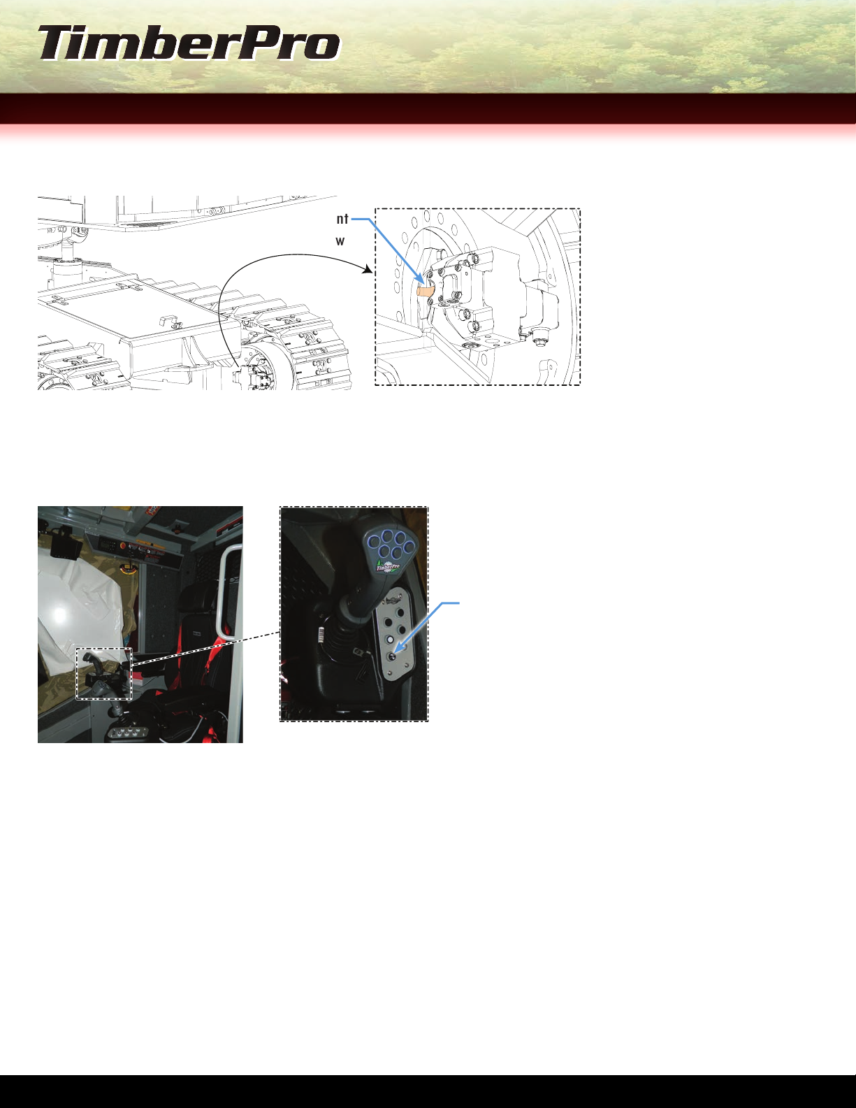
Min. Displacement
Adjustment Screw
FIGURE 1, MIN. DISPLACEMENT
SCREW LOCATION ON TRACK MOTOR
1. With the engine running, engage the motor shift selection located on the hand controls in the cab into Turtle Mode. See
Figure 2 below.
FIGURE 2, TURTLE MODE
SELECTION IN CAB
Turtle Mode Shift
Selection
2. Turn the track drive motor Min. Displacement Screw in until you feel it make contact with the internal swash-plate. See
Figure 1 for screw location.
3. Raise one track off the ground and time how long it takes for that track to make a complete revolution.
4. Turn the displacement screw inward on the raised track and calculate the time it takes to reach the desired rpm.
5. Once the desired rpm is reached, measure the portion of screw that is left above the locknut.
6. Use the measurement from the previous step to adjust the screw on the other track. The same measurement should be
applied.
7. Raise the other track off the ground and time the time how long it takes for the second track to make one complete
revolution. Adjust the Min. Displacement Screw as necessary to reach the same rpm as the side just adjusted.
CHANGING MIN. DISPLACEMENT PRESSURE PROCEDURE END
SecTioN 11
P 14 of 17 P 15 of 17
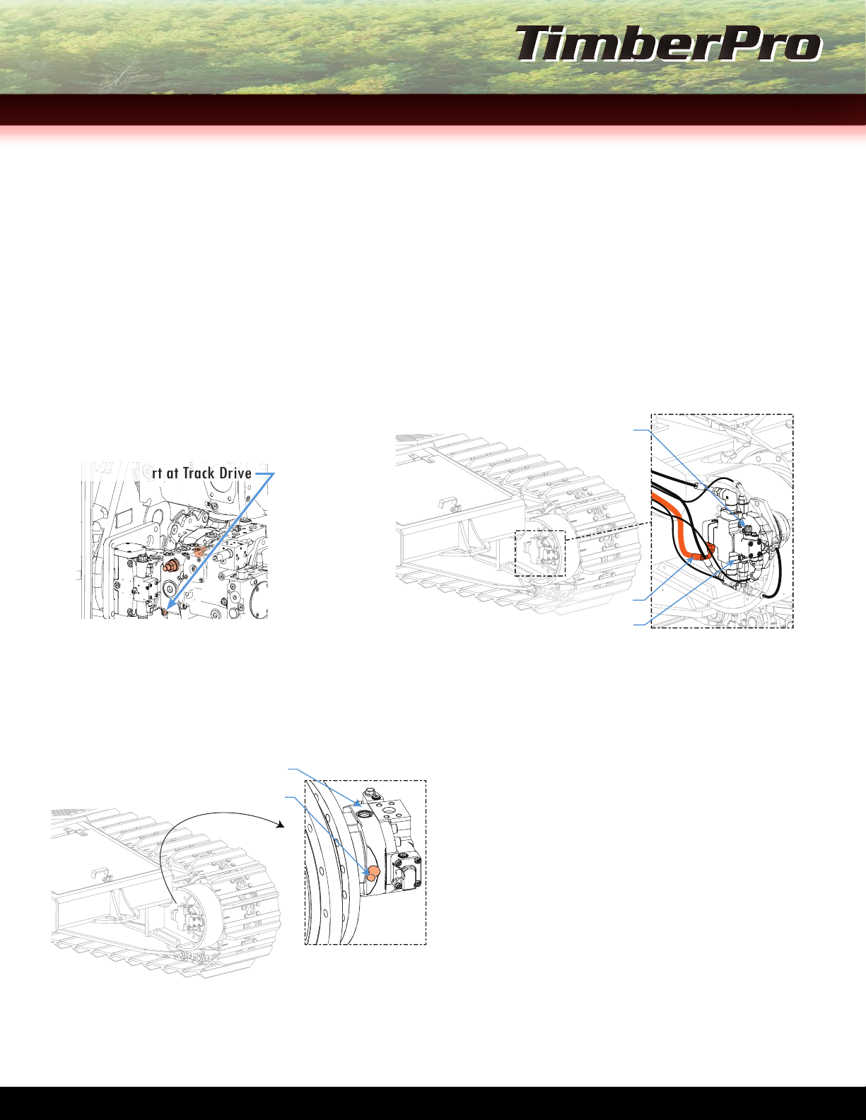
SeTTiNG ShifT-pOiNT aNd beGiNNiNG Of reGULaTiON
1. Disconnect and remove the Motor Shift Hose from the track drive motor. Leave the MS port open to breath. See Figure 2
below for MS Hose and port location on motor.
2. Install a 6,000 psi gauge into the MH Test Port. See Figure 1 on next page for MH Test Port location.
3. Run engine at a minimum of 1400rpm.
4. Have operator stroke pump and adjust POR to desired pressure.
5. Remove gauge from the track drive pump MH port and install gauge at M1 port on the track drive motor. See Figure 2
below for M1 Test Port location on motor.
FIGURE 1, MH TEST
PORT AT TRACK DRIVE
MH Test Port at Track Drive
M1 Port
Track Drive Motor
Motor Shift Hose
FIGURE 2,
TRACK DRIVE MOTOR
6. Once the gauge is installed on the track drive motor M1 port, have the operator stroke the pump once again. Use the
Pressure Adjustment Valve to set the Shift Pressure to 1/2 the amount that the track drive pump was set to in Step 2.
See Figure 3 below for pressure adjustment valve location.
PRESSURE ADJUSTMENT EXAMPLE
If the pressure gathered from the MH
Test Port on the track drive motor in
Step 2 was 5200 psi then the adjusted
p r e s s u r e s h o u l d b e s e t t o 2 6 0 0 p s i .
Pressure Adjustment Valve
Track Drive Motor
FIGURE 3, TRACK DRIVE MOTOR
ADJUSTMENT VALVE
TL/TN-775 MAchiNe iNiTiAL SeT-UPGUideSecTioN 12
This manual suits for next models
3
Table of contents
Other TimberPro Industrial Equipment manuals


