TIME MARK 153 User manual
DESCRIPTION
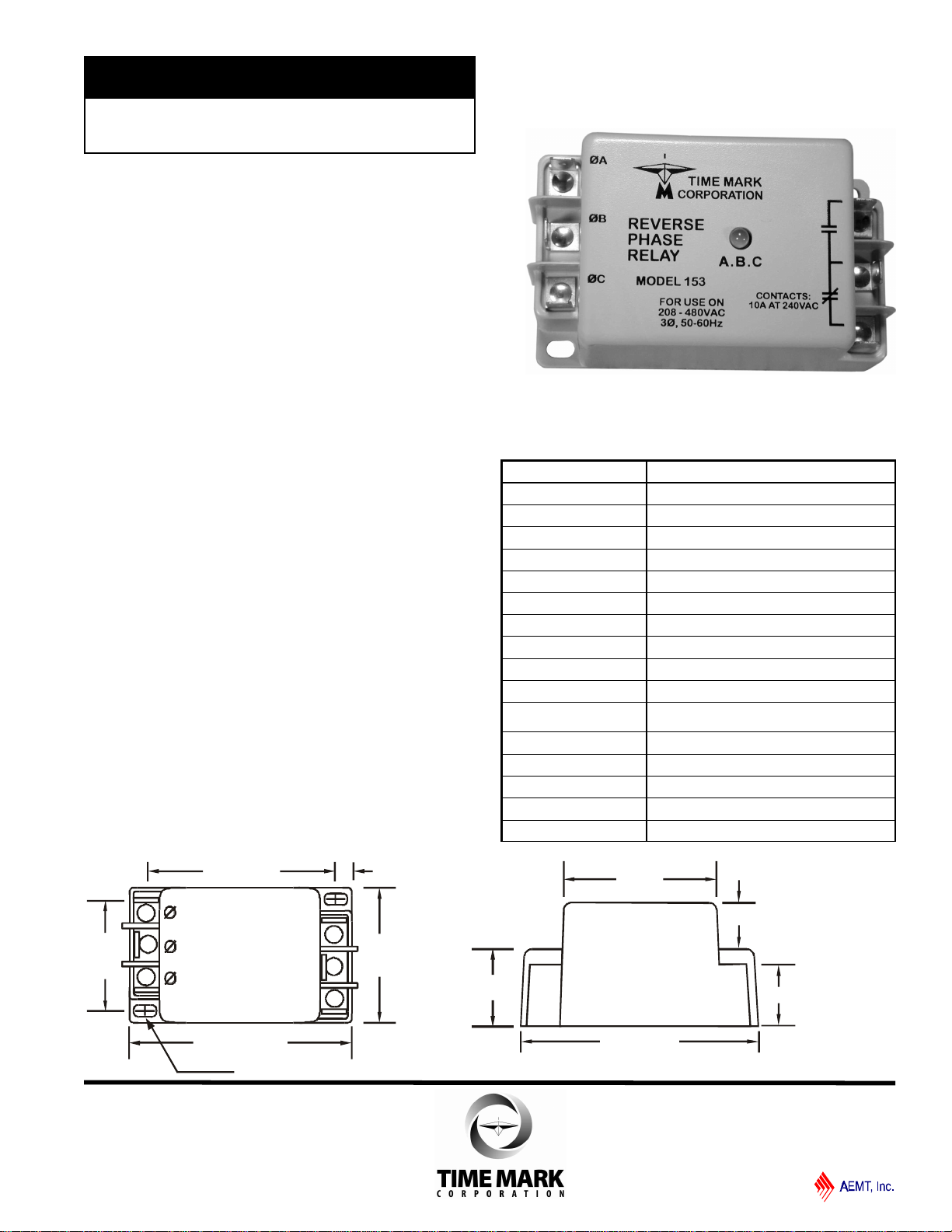
The Model 153 Reverse Phase Relay is designed to
continuously monitor phase rotation of 3-phase lines.
This device should be used in applications where proper
phase rotation is critical, such as fan motors,
compressors, grinders, elevators, etc.
The solid-state sensing circuit drives an internal
electromechanical relay which energizes when power,
with correct phase rotation, is applied.
The relay will not energize if the applied phases are
reversed. It will de-energize if phase rotation is reversed
while the motor is running. An LED indicator will
illuminate with correct ABC phase rotation.
DIMENSIONS
SPECIFICATIONS
Model 153
Nominal voltage 190-500 VAC (phase to phase)
Frequency 50 to 60 Hz
Power Consumption 2W per phase
Transient protection 2500 VRMS for 10 msec
Repeat accuracy ± 0.1 % (fixed conditions)
Response time .05 seconds
Reset time .05 seconds
Reset type Automatic
Dead band Approximately 2 %
Output contacts SPDT 10A at 240 VAC resistive
Expected relay life Mechanical: 10 million operations
Electrical: 100,000 at rated load
Operating temp -40º to +131º F
Humidity tolerance 0-97 % w/o condensation
Case material ABS plastic
Mounting Surface
Weight 4oz.
lSenses phase reversal on Wye or Delta
l190 to 500 VAC range
ll Surface-mount Enclosure
ll Low power consumption
MODEL 153
Reverse Phase Relay
TIME MARK is a division of
Telephone: Main -(918) 438-1220
Sales -(800) 862-2875
Fax: (918) 437-7584
E-mail: sales@time-mark.com
Internet:http://www.time-mark.com
July 2004
© 2004 TIME MARK CORPORATION
11440 East Pine Street
Tulsa, Oklahoma 74116
2.66"
1.25"
3.9"
.76"
.95"
3.2"
A
B
C
NO
NC
C
2.19"
.23"
3.65"
.30" x .19"
1.79"
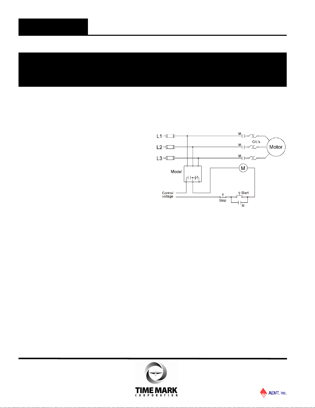
TYPICAL APPLICATION
INSTALLATION
Mount the Model 153 in the desired location.
Connect the 3-phase power to the terminals marked A,
B, and C.
Connect the control circuit to the terminals with the
contact markings. Refer to the Typical Application
wiring diagram for additional information.
If the relay contacts do not transfer when power is
applied (LED indicator-Off), check that all three
voltages are correct.
If power is present and the voltage is correct, remove
power. Reverse two of the three phase connections.
Re-apply power.
The contacts should transfer to the normal condition
(normally open contacts closed; LED indicator-On).
Calibrations or adjustments are not required.
TROUBLESHOOTING
Should the relay fail to operate properly, check that all
three voltages are present and are of the correct level.
Check all fuses and verify that all wiring connections are
correct. Should problems persist, contact the factory for
assistance.
WARRANTY
The Model 153 Reverse Phase Relay is covered by
Time Mark Corporation’s exclusive 5-Year
Unconditional Warranty. Should this device fail, for
any reason, within five years from the date of purchase,
we will repair or replace it. Contact the Time Mark
Sales department, Monday through Friday; 8 a.m. to 5
p.m., CST, for further details.
AB
NO NCC
C
153
MODEL 153 Reverse Phase Relay
READ ALL INSTRUCTIONS BEFORE INSTALLING, OPERATING OR SERVICING THIS DEVICE.
KEEP THIS DATA SHEET FOR FUTURE REFERENCE.
GENERAL SAFETY
POTENTIALLY HAZARDOUS VOLTAGES ARE PRESENT AT THE TERMINALS OF THE MODEL 153.
ALL ELECTRICAL POWER SHOULD BE REMOVED WHEN CONNECTING OR DISCONNECTING WIRING.
THIS DEVICE SHOULD BE INSTALLED AND SERVICED BY QUALIFIED PERSONNEL.
Installation Instructions
TIME MARK is a division of
Telephone: Main -(918) 438-1220
Sales -(800) 862-2875
Fax: (918) 437-7584
E-mail: sales@time-mark.com
Internet:http://www.time-mark.com
July 2004
© 2004 TIME MARK CORPORATION
11440 East Pine Street
Tulsa, Oklahoma 74116
DESCRIPTION
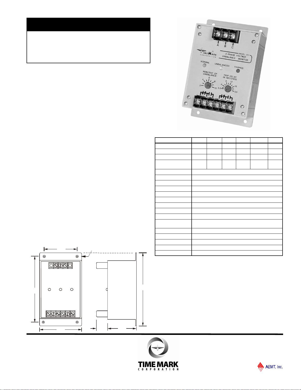
The Model 200 3-Phase Voltage Unbalance Monitor
is designed to continuously monitor a three-phase line
for unbalanced voltage conditions.
This device will only energize the relay if an unbalance
exists. Zero volts on all three phases is considered a
balanced condition. This allows the Model 200 to be
used with shunt breakers, so that main power can be
restored without resetting breakers.
The solid-state sensing circuit drives an internal
electromechanical relay. Indicator lights on the monitor
show when the voltage balance is within an acceptable
range; when an unbalance exists; and when the relay is
actually tripped.
When an acceptable voltage balance is reapplied, the
Model 200 will automatically reset the relay.
DIMENSIONS
.19 dia. typ.
6.06"
5.5"5.5"
3.88"
3.0"
2.08".62"
MODEL 200
3-Phase Voltage
Unbalance Monitor
ll Detects Unbalanced Voltages
ll Percent of Unbalance Adjustment
ll Automatic Reset
TIME MARK is a division of
Telephone: Main -(918) 438-1220
Sales -(800) 862-2875
Fax: (918) 437-7584
E-mail: sales@time-mark.com
Internet:http://www.time-mark.com
Doc No. 87A320 04/03
© 2003 TIME MARK CORPORATION
11440 East Pine Street
Tulsa, Oklahoma 74116
SPECIFICATIONS
Model A200 B200A B200B C200 D200 EX200
Nominal AC Voltages 120VAC 208VAC 240VAC 480VAC 575VAC 380VAC
Voltage Range ± 15% ± 15% ± 15% ± 15% +5 to -15% ± 15%
Frequency 60Hz 60Hz 60Hz 60Hz 60Hz 50Hz
Power Consumption
(per phase) 0.5W 1W 1W 2W 2W 2W
Transient Protection 2500VRMS for 10msec
Repeat Accuracy ± 0.1% (fixed conditions)
Unbalance Adjustment 2% to 10%
Response Time 100 msec
Reset Time Fixed 1 sec
Dropout Time Adjustable 0.2 to 20 seconds
Reset Type Automatic
Dead Band 0.5% max
Contact Rating DPDT 10 amps at 240VAC resistive
Expected Relay Life Mech: 10 million operations
Elec: 100,000 operations at rated load
Operating Temp -40° to +131° F
Humidity Tolerance 0-97% w/o condensation
Mounting Surface
Enclosure Material ABS plastic
Weight 10 oz.
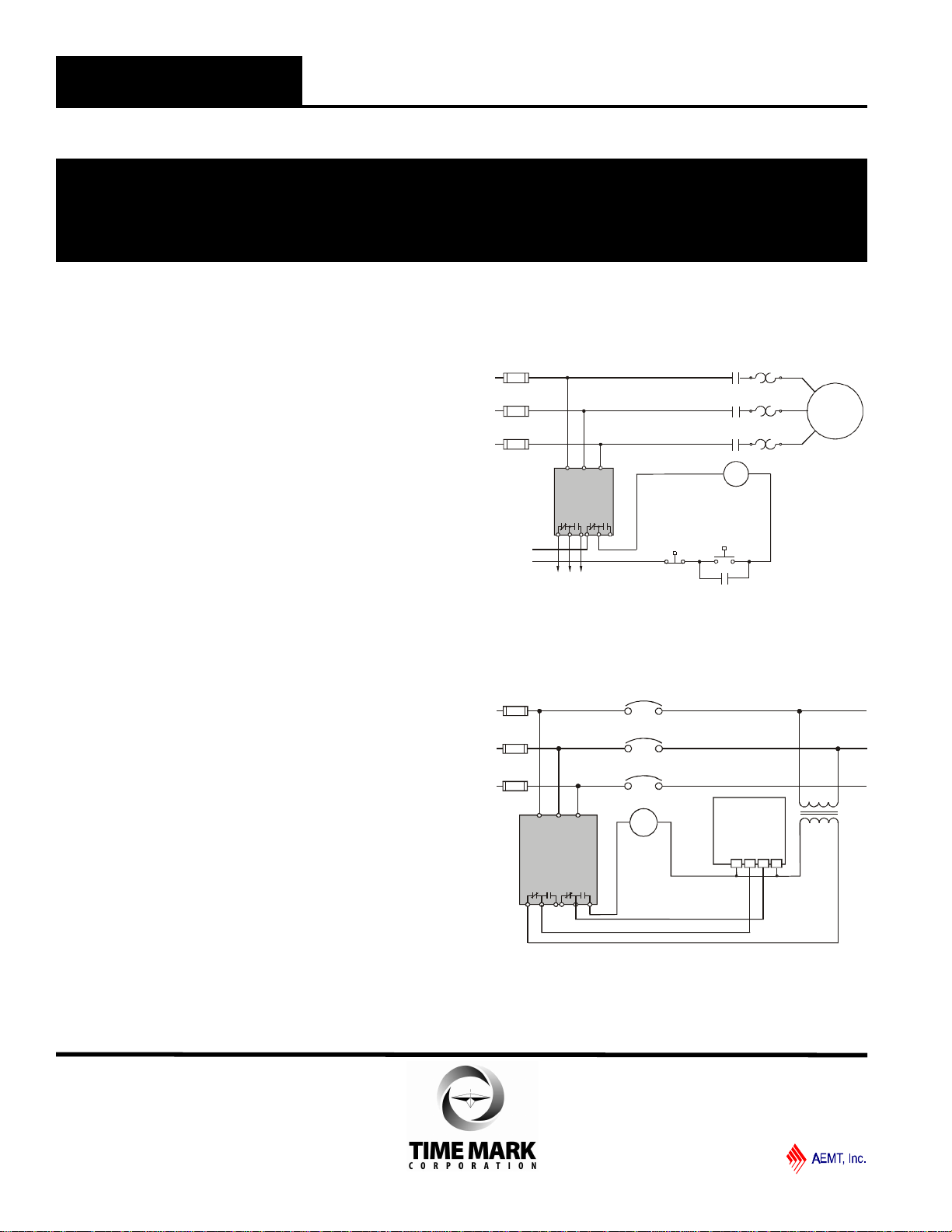
INSTALLATION
Set PERCENT OF UNBALANCE fully clockwise.
Set TRIP DELAY IN SECONDS fully counter-
clockwise.
Connect the 3-phase wires to the terminals marked ‘A’,
‘B’ and ‘C’.
Connect the control wires to the terminals with the relay
contact markings. The contact markings on the unit are
the NORMAL or OFF condition of the contacts.
Apply power. NORMAL indicator should be ON.
ADJUSTMENT
Rotate the PERCENT OF UNBALANCE adjustment pot
to the desired setting.
Set the TRIP DELAY adjustment to the desired amount
of delay to prevent nuisance trips.
Should nuisance trips occur, increase the TRIP DELAY
IN SECONDS setting. Any adjustments should be
made in very small increments.
WARRANTY
The Model 200 3-Phase Voltage Unbalance Monitor
is covered by Time Mark Corporation’s exclusive 5-
Year Unconditional Warranty. Should this device fail,
for any reason, within five years from the date of
purchase, we will repair or replace it free. Contact the
Time Mark Sales department, Monday through Friday;
8 a.m. to 5 p.m., CST, for further details.
TYPICAL MOTOR APPLICATION
MODEL 200 3-Phase Voltage Unbalance Monitor
READ ALL INSTRUCTIONS BEFORE INSTALLING, OPERATING OR SERVICING THIS DEVICE.
KEEP THIS DATA SHEET FOR FUTURE REFERENCE.
GENERAL SAFETY
POTENTIALLY HAZARDOUS VOLTAGES ARE PRESENT AT THE TERMINALS OF THE MODEL 200.
ALL ELECTRICAL POWER SHOULD BE REMOVED WHEN CONNECTING OR DISCONNECTING WIRING.
THIS DEVICE SHOULD BE INSTALLED AND SERVICED BY QUALIFIED PERSONNEL.
Installation Instructions
TYPICAL SHUNT BREAKER APPLICATION
Model 200
L1
L2
L3 Shunt
Trip
Breaker
Model 410
1 432
Motor
Model
200
M
O/L's
M
Start
Stop
Control
voltage
Optional
alarm circuit
M
M
L2
L3
L1
M
TIME MARK is a division of
Telephone: Main -(918) 438-1220
Sales -(800) 862-2875
Fax: (918) 437-7584
E-mail: sales@time-mark.com
Internet:http://www.time-mark.com
Doc No. 87A320 04/03
© 2003 TIME MARK CORPORATION
11440 East Pine Street
Tulsa, Oklahoma 74116
Shows No Power Applied
Shows No Power Applied
SPECIFICATIONS
Model A246 B246 EX246
Nominal AC Voltage 120 208/240 380
Adjustment Range
Low:
High:
85-125 V
110-140 V
160-260 V
210-280 V
300-400 V
350-450 V
Frequency 60 Hz 60 Hz 50 Hz
Power Consumption (per phase) 1 W 1.5 W 2 W
Transient Protection 2500V for 10 msec
Repeat Accuracy ±0.1% of set point (fixed conditions)
Response/Reset Time 50 msec
Reset type Automatic
Dead Band 2%
Contact Rating SPDT 10A at 240VAC resistive
Expected Relay Life Mech: 10 million operations
Elec: 100,000 at rated load
Operating Temperature -40º to +131º F
Humidity Tolerance 0-97% w/o condensation
Enclosure Material ABS plastic
Weight 6 oz.
Mounting 8-pin socket *order separately
Agency approval CSA CSA
* Order 8-pin socket number 51X120
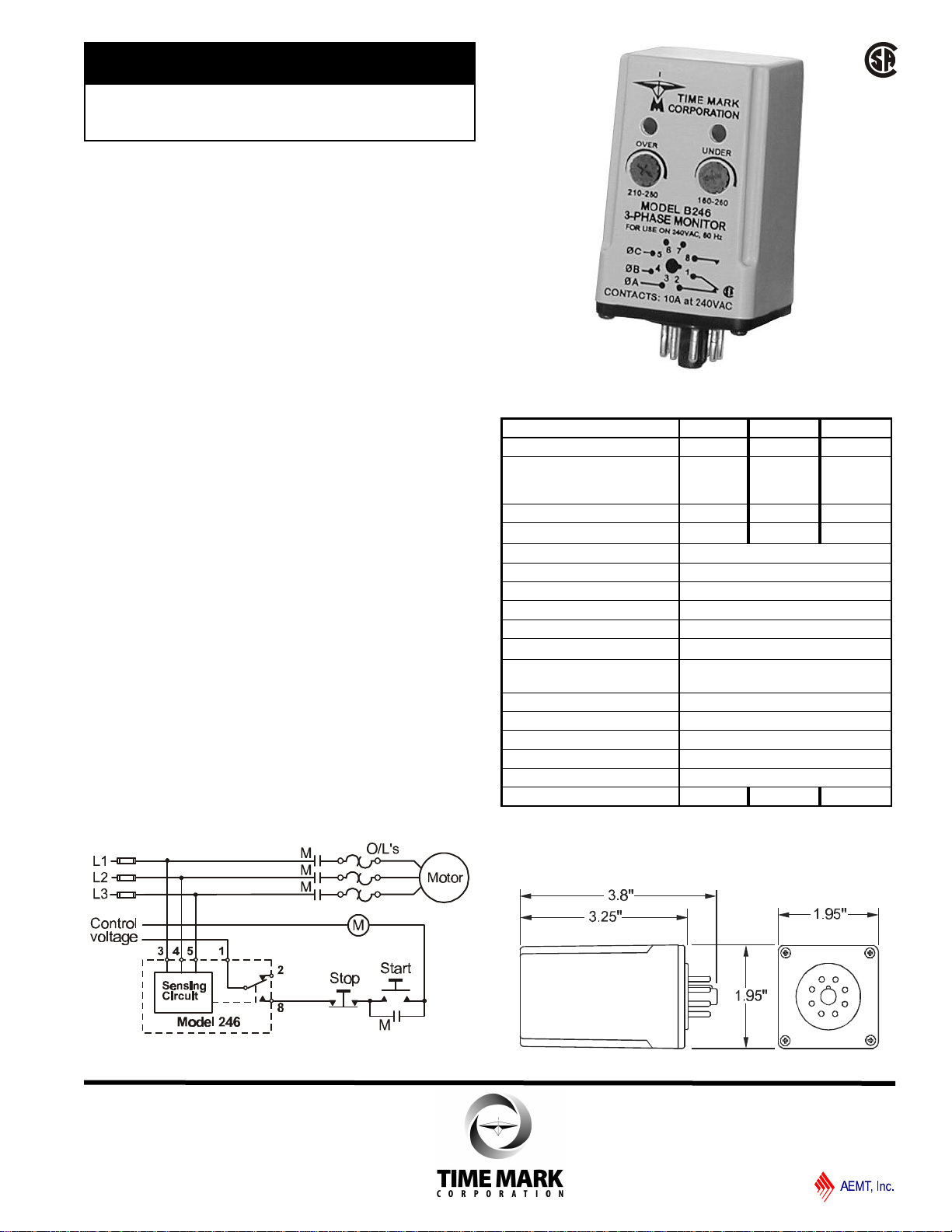
DESCRIPTION
The Model 246 3-Phase Monitor is designed to
continuously monitor 3-phase power lines for phase
loss, phase reversal, low voltage and high voltage. This
device features solid-state voltage and phase angle
sensing circuits, which drive a SPDT electromechanical
relay. A neutral is not required, allowing the Model 246
to be used with either Wye or Delta systems.
Three versions of the Model 246 cover the 120 and
208/240VAC, 60 Hz and the 380VAC, 50 Hz. In
addition, the models A246 and B246 are now CSA
Certified.
Each option on the Model 246 monitor is adjustable
throughout its operating range. The adjustment pots
and LED indicators for OVER VOLTAGE and UNDER
VOLTAGE are mounted on the front of the unit for easy
access.
DIMENSIONS
TYPICAL APPLICATION
ll Monitors for Phase Loss or
Reversal, Low and Over Voltage
ll Automatic Reset
ll CSA Certified
ll 5 Year Unconditional Warranty
MODEL 246
3-Phase Monitor
TIME MARK is a division of
Telephone: Main -(918) 438-1220
Sales -(800) 862-2875
Fax: (918) 437-7584
E-mail: sales@time-mark.com
Internet:http://www.time-mark.com
Doc No. 87A112 12/00
© 2000 TIME MARK CORPORATION
11440 East Pine Street
Tulsa, Oklahoma 74116
Shows No Power Applied

ADJUSTMENT PROCEDURE
Set UNDER VOLTAGE level: Rotate the UNDER
VOLTAGE adjustment pot clockwise, until the contacts
transfer (UNDER VOLTAGE LED-On). Slowly turn the
UNDER VOLTAGE adjustment counter-clockwise until the
contacts reset (UNDER VOLTAGE LED-Off).
Set OVER VOLTAGE level: Turn the OVER VOLTAGE
adjustment pot counter-clockwise, until the contacts
transfer (OVER VOLTAGE LED-On). Slowly turn the
OVER VOLTAGE adjustment pot clockwise until the
contacts reset (OVER VOLTAGE LED-Off).
Nuisance tripping: The settings achieved by these adjust-
ments (above), will be correct for most applications.
Should nuisance tripping occur, turn the OVER VOLTAGE
and the UNDER VOLTAGE adjustments slightly further,
widening the operating band.
PIN DIAGRAM
TROUBLESHOOTING
Should the Model 246 3-Phase Monitor fail to operate,
check all connections. Verify that all three voltages are
present, and check all fuses. Should problems persist,
contact the factory for assistance.
WARRANTY
The Model 246 3-Phase Monitor is covered by Time
Mark Corporation’s exclusive 5-Year Unconditional
Warranty. Should this device fail, for any reason, within
five years from the date of purchase, we will repair or
replace it free. Contact the Time Mark Sales
department, Monday through Friday; 8 a.m. to 5 p.m.,
CST, for further details.
WARNING
The Model 246 is not to be used with input
voltages greater than those for which the unit was
designed.
140VAC for Model A246
280VAC for Model B246
INSTALLATION
Connect the input power to the 8-pin socket, following
the Model 246 pin diagram, pictured on the unit, and on
this data sheet. Insert the Model 246 into the socket
and apply power.
If the contacts do not transfer (both LEDs-off), check
that all three phases are present and of the correct
voltage. If power is correct, rotate the UNDER
VOLTAGE adjustment counter-clockwise, and the
OVER VOLTAGE adjustment clockwise, to widen the
operating band.
If the contacts still do not transfer, remove power and
reverse two of the three phase wires, at the socket
(phase rotation is reversed). Re-apply the power. The
contacts should transfer to provide a signal path
between pins 1 & 8 (both LEDs-off).
NOTE: When installing the Model 246 Monitor in
areas of high humidity or contamination, it is
recommended that the base area and all exposed metal
parts of the socket be coated liberally with a good
quality silicon grease, such as Dow Corning DC-4 or
DC-4X. Insert the unit into the socket and wipe off
excess grease around the base. This will prevent the
entrance of moisture and other contaminates into the
base and socket areas.
MODEL 246 3-Phase Monitor
READ ALL INSTRUCTIONS BEFORE INSTALLING, OPERATING OR SERVICING THIS DEVICE.
KEEP THIS DATA SHEET FOR FUTURE REFERENCE.
GENERAL SAFETY
POTENTIALLY HAZARDOUS VOLTAGES ARE PRESENT AT THE TERMINALS OF THE MODEL 246.
ALL ELECTRICAL POWER SHOULD BE REMOVED WHEN CONNECTING OR DISCONNECTING WIRING.
THIS DEVICE SHOULD BE INSTALLED AND SERVICED BY QUALIFIED PERSONNEL.
Installation Instructions
TIME MARK is a division of
Telephone: Main -(918) 438-1220
Sales -(800) 862-2875
Fax: (918) 437-7584
E-mail: sales@time-mark.com
Internet:http://www.time-mark.com
Doc No. 87A112 12/00
© 2000 TIME MARK CORPORATION
11440 East Pine Street
Tulsa, Oklahoma 74116
SPECIFICATIONS
Model 2500-120
2501-120 2500-208
2501-208 2500-240
2501-240 2500-380
2501-380 2500-415
2501-415 2500-480
2501-480 2500-600
2501-600
Nominal AC Voltage 120 208 240 380 415 480 600
Adjustment Range 84-114V 146-198V 168-229V 266-361V 290-394V 336-456V 420-570V
Frequency 50/60 Hz
Unbalance adj
range 2 to 10% per NEMA specifications
Trip Delay adj range 1 to 10 seconds (1 sec increments)
Power Consumption 4.5W per phase
Repeat Accuracy ± 1% of full scale
Reset Time 150 msec nominal
Reset Type Automatic
Dead Band 2% of full scale
Output Contacts SPDT 30 amps at 28VDC/300VAC 50/60 Hz
5 amps at 480/600VAC 50/60 Hz 0.75 PF
Operating Temp -4º to +131º F
Humidity Tolerance 0-97% without condensation
Enclosure Material ABS plastic
Weight 2 lbs. 5 oz.
Mounting Surface
Agency Approval UL Listed to U.S. and Canadian safety standards
ll Monitors for Phase Loss or Reversal,
Low Voltage or Voltage Unbalance
ll Automatic Reset
ll Heavy Duty Output Contacts
ll UL Listed to U.S. and Canadian
Safety Standards
MODEL 2500
MODEL 2501
3-Phase Monitor
DIMENSIONS
TIME MARK is a division of
Telephone: Main -(918) 438-1220
Sales -(800) 862-2875
Fax: (918) 437-7584
E-mail: sales@time-mark.com
Internet:http://www.time-mark.com
Doc No. 87A429 12/00
© 2000 TIME MARK CORPORATION
11440 East Pine Street
Tulsa, Oklahoma 74116
TYPICAL APPLICATION -Motor
Shows No Power Applied
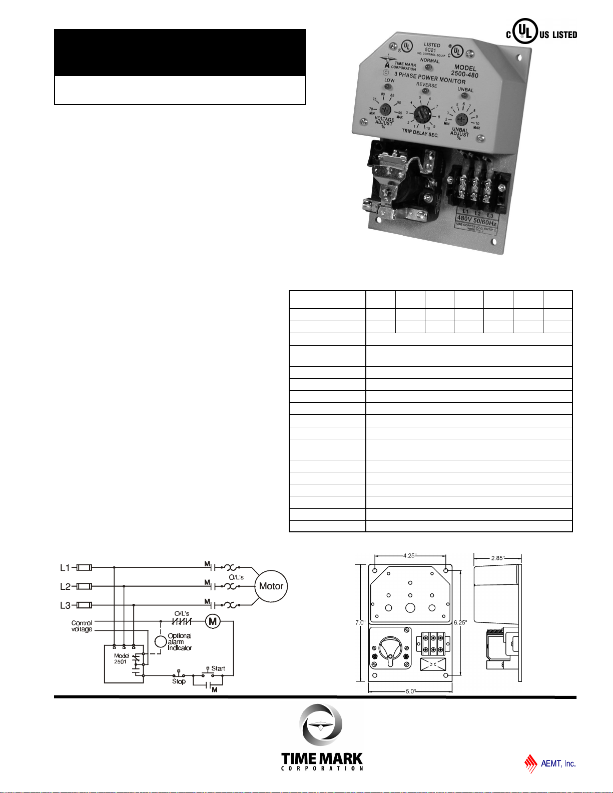
DESCRIPTION
The Models 2500 and 2501 3-Phase Monitors are
designed to continuously monitor the voltages of a 3-phase
power distribution system for abnormal conditions. The
monitors feature solid-state voltage and phase angle
sensing circuits which drive a SPDT electromechanical
output relay. A neutral connection is not required with either
the Model 2500 or 2501. This allows each model to be
connected to any three phase WYE or DELTA configured
power distribution system.
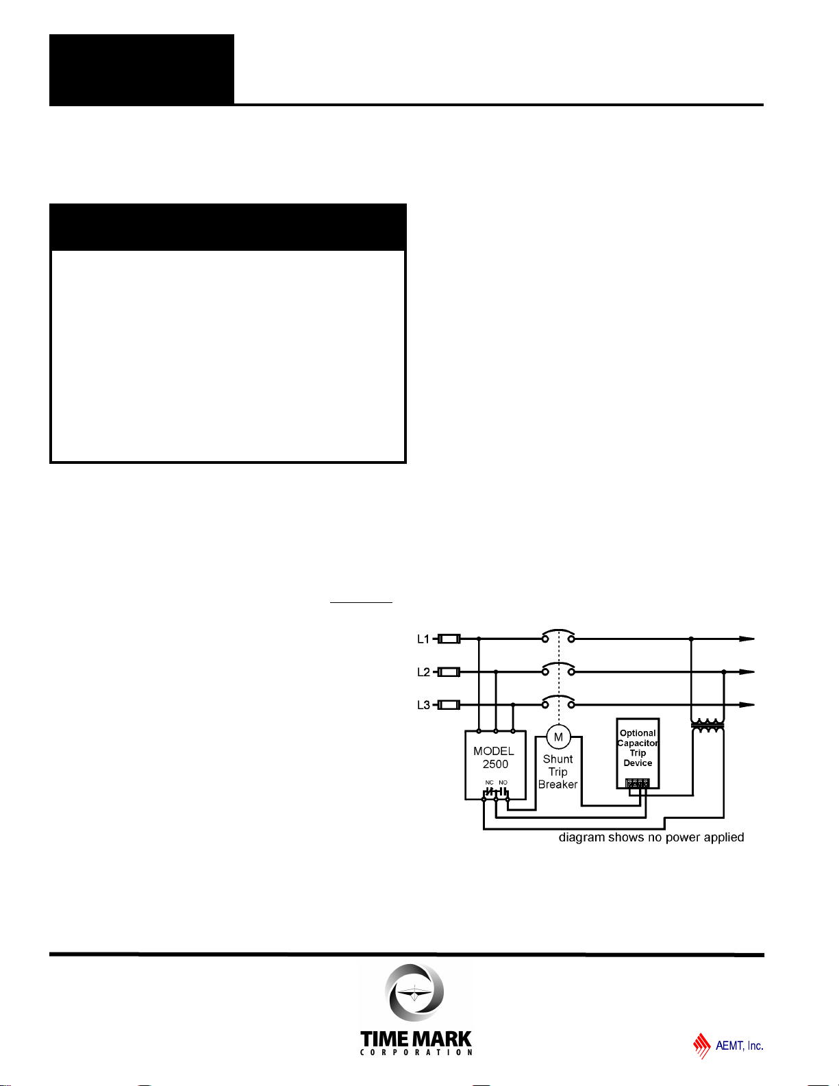
When the correct voltage and phase sequence is applied to
a specified Model 2500, the output relay will not energize.
An under voltage, phase reversal, phase unbalance or
phase loss condition will cause the output relay to
energize, even if regenerated voltage is present. Complete
power loss will not cause Model 2500 to trip.
When the correct voltage and phase sequence is applied to
a specified Model 2501, the output relay will energize. An
under voltage, phase reversal, phase unbalance, or phase
loss condition will cause the output relay to de-energize.
Each option on the Model 2500 or 2501 is adjustable
throughout it’s operating range. The adjustment pots and
LED indicators for VOLTAGE ADJUST, UNBALANCE
ADJUST and TIME DELAY are mounted on the front of the
unit, for easy access.
Seven versions of both the Model 2500 and the Model 2501
cover voltage ranges from 120 to 600 VAC. All models are
UL Listed to U.S. and Canadian safety standards.
ADJUSTMENT
Note: During adjustment, you may want to install a
jumper across the control contacts or open circuit,
depending on your control configuration, to prevent
cycling the load on and off.
Rotate the VOLTAGE ADJUST to the desired percent of
nominal voltage, or slowly clockwise, until the contacts
transfer to the failed condition (LOW indicator-ON).
Slowly turn the adjustment counter-clockwise until the
contacts reset to the normal condition (LOW indicator-OFF;
NORMAL indicator-ON).
Remove the jumper from the control contacts, if installed.
This setting will be correct for most applications. If nuisance
tripping occurs, turn the VOLTAGE ADJUST slightly counter-
clockwise, or increase the trip delay time.
Any adjustments to the VOLTAGE ADJUST, to eliminate
nuisance tripping, should be made in small increments, until
the true nuisance trips are eliminated. Adjust the TRIP
DELAY and UNBAL ADJUST as required by the system.
TYPICAL APPLICATION -Shunt Breaker
MODEL 2500
MODEL 2501 3-Phase Monitor
READ ALL INSTRUCTIONS BEFORE INSTALLING, OPERATING OR SERVICING THIS DEVICE.
KEEP THIS DATA SHEET FOR FUTURE REFERENCE.
Installation Instructions
INSTALLATION
Mount the Model 2500 or 2501 in a stable location,
observing all precautions outlined in the statement
above. Mounting hardware is not included.
Connect the control wiring to the terminals with the
contact markings (refer to the diagram on the unit).
Markings shown on the unit are in the power off
condition. Apply power.
If the contacts transfer (NORMAL indicator-Off), check
the LOW, REVERSE, and UNBALANCE indicators for a
possible fault condition. If no indicators are lit, check
that all three phases are present and of the correct
voltage.
If all phases are correct and the LOW indicator is ON,
rotate the VOLTAGE ADJUST until the light just goes
out.
If the UNBAL indicator is ON, rotate the UNBAL
ADJUST until the light just goes out.
NOTE: During adjustment you may find the UNBAL
ADJUST and the TRIP DELAY adjustment has no
effect. Check for phase loss.
If the REVERSE indicator is ON, remove power and
reverse any two of the three input wires and re-apply
power. The contacts should transfer to the normal
condition (normally-open contacts open, NORMAL indi-
cator-ON).
DANGER
•HAZARD OF ELECTRIC SHOCK, BURN OR
EXPLOSION
•POWER CONTROL & INSTRUMENT CIRCUITS MAY
BE SUPPLIED BY REMOTE SOURCES
•THIS DEVICE SHOULD ONLY BE INSTALLED OR
SERVICED BY QUALIFIED PERSONNEL
•TURN OFF ALL POWER SUPPLYING THIS DEVICE
BEFORE WORKING ON MONITOR
•FAILURE TO DO SO WILL RESULT IN DEATH OR
SEVERE PERSONAL INJURY
TIME MARK is a division of
Telephone: Main -(918) 438-1220
Sales -(800) 862-2875
Fax: (918) 437-7584
E-mail: sales@time-mark.com
Internet:http://www.time-mark.com
Doc No. 87A429 12/00
© 2000 TIME MARK CORPORATION
11440 East Pine Street
Tulsa, Oklahoma 74116
WARRANTY
The Model 2500 and Model 2501 3-Phase Monitors are
covered by Time Mark Corporation’s exclusive 5-Year
Unconditional Warranty. Should this device fail, for any
reason, within five years from the date of purchase, we will
repair or replace it free. Contact the Time Mark Sales
department for further details.
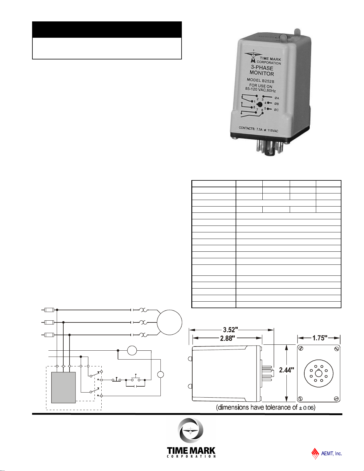
DESCRIPTION
The Model 252 3-Phase Monitor continuously monitors
3-phase power lines for abnormal conditions. When
properly adjusted, the Model 252 will detect phase loss
on a loaded motor even when regenerated voltage is
present.
This device consists of a solid-state voltage and phase-
angle sensing circuit, driving an electromechanical relay
with one SPDT and one SPST contact. When correct
voltage and phase rotation are applied, the internal
relay will energize. A fault condition will de-energize the
relay. When the fault is corrected the Model 252 will
automatically reset.
The Model 252 does not require a neutral connection
and can be used with WYE or DELTA configured
systems. Four versions cover 120V, 208/240V and
480V, 60Hz, and 380V, 50Hz. Adjustment ranges are
sufficiently wide to allow for proper adjustment to
existing conditions. Two LED indicators are provided to
aid in adjustment and system troubleshooting.
ll Detects Phase Loss, Low Voltage
and Phase Reversal
ll 50 Hz and 60 Hz versions
ll Automatic Reset
MODEL 252
3-Phase Monitor
L1
L2
L3
M
M
M
M
MOTOR
O/L's
Start Remote
Indicator
Lamp
Stop
Control
Voltage
Model
252
M
3 4 56 1 2
8
7
TYPICAL APPLICATION
TIME MARK is a division of
Telephone: Main -(918) 438-1220
Sales -(800) 862-2875
Fax: (918) 437-7584
E-mail: sales@time-mark.com
Internet:http://www.time-mark.com
Doc No. 87A373 12/00
© 2000 TIME MARK CORPORATION
11440 East Pine Street
Tulsa, Oklahoma 74116
DIMENSIONS
Shows No Power Applied
SPECIFICATIONS
Model B252B 252B A252B EX252B
Nominal AC Voltage 120VAC 208/240VAC 480VAC 380VAC
Adjustment Range 85-120VAC 160-240VAC 380-480VAC 300-380VAC
Frequency 60 Hz 50Hz
Power Consumption 0.25 W 0.50 W 1.5 W 1.25 W
Transient Protection 2500V for 10 msec
Repeat Accuracy 0.1% of set point (fixed conditions)
Response Time 0.05 seconds
Reset Time 0.05 seconds
Reset Type Automatic
Dead Band 2%
Output Contacts 1 -SPDT 1 -SPST (N.O.)
Contact Rating 5A at 240VAC resistive
Expected Relay Life Mech: 10 million operations
Elec: 100,000 at rated load
Operating Temp -40º to 131º F
Humidity Tolerance 97% w/o condensation
Enclosure Material ABS plastic
Mounting 8-pin socket (*order separately)
Weight 5 oz.
*Order 8-pin socket number 51X120

INSTALLATION
Mount the socket in a suitable enclosure. A NEMA
approved enclosure, designed for socket-mounted relays,
is available from Time Mark Corporation.
Connect the 3-phase power to terminals 3, 4 and 5 on the
socket. Phase rotation may be verified using a Time Mark
Model 108A or 108B Phase Sequence Detector.
Connect the load control wiring to the appropriate terminals
on the socket. The SPST contacts (pins 6 and 7) are
electrically isolated from the SPDT contacts.
For motor control and phase loss alarm applications;
use the SPDT contacts.
For auxiliary indicator applications; use the appropriate
SPST contacts.
Insert the Model 252 into the socket.
Apply power. If the contacts do not transfer, (TRIP indica-
tor-On ), check that all phases are present and of the
correct voltage. If power is correct, rotate the level
adjustment counter-clockwise.
If the contact still does not transfer, remove power and
reverse two of the three phase wires at the socket (phase
rotation is reversed). Re-apply power. The contact should
transfer to provide a signal path between both sets of
normally-open contacts. The green LED (NORMAL)
should be lit.
Note: When installing the Model 252 in areas of high humidity
or contamination, it is recommended that the base area and all
exposed metal parts of the socket be coated liberally with a
good quality silicon grease, such as Dow Corning DC-4 or DC-
4X. Insert the unit into the socket and wipe off excess grease
around the base. This will prevent the entrance of moisture
and other contaminants into the base and socket area.
ADJUSTMENT
The following procedure will adjust the Model 252 to trip
below the nominal voltage.
Rotate the level adjustment clockwise, until the relay
contact transfers (TRIP indicator On). Slowly turn the
adjustment counter-clockwise, until the contact resets.
This setting will be correct for most applications.
Should nuisance tripping occur, turn the adjustment slightly
farther counter-clockwise, lowering the trip level. A more
accurate adjustment procedure requires a 3-phase variac,
allowing the voltage to be lowered to a specific voltage.
The Model 252 can then be set to trip at this precise
voltage level, when installed in the motor control circuit.
Factory set versions are also available.
TROUBLESHOOTING
Should the Model 252 fail to operate properly, check that
all three voltages are present and are of the correct level
and phase rotation (a Model 108A or 108B Phase
Sequence Detector may be used to verify phase rotation).
Check all fuses and verify that all wiring connections are
correct. Should problems persist, contact the manufacturer
at 800-862-2875.
WARRANTY
The Model 252 3-Phase Monitor is covered by Time
Mark Corporation’s exclusive 5-Year Unconditional War-
ranty. Should this device fail, for any reason, within five
years from the date of purchase, we will repair or replace it,
free. Contact the Time Mark Sales department for further
information.
PIN DIAGRAM
A
B
C
MODEL 252 3-Phase Monitor
READ ALL INSTRUCTIONS BEFORE INSTALLING, OPERATING OR SERVICING THIS DEVICE.
KEEP THIS DATA SHEET FOR FUTURE REFERENCE.
GENERAL SAFETY
POTENTIALLY HAZARDOUS VOLTAGES ARE PRESENT AT THE TERMINALS OF THE MODEL 252.
ALL ELECTRICAL POWER SHOULD BE REMOVED WHEN CONNECTING OR DISCONNECTING WIRING.
THIS DEVICE SHOULD BE INSTALLED AND SERVICED BY QUALIFIED PERSONNEL.
Installation Instructions
TIME MARK is a division of
Telephone: Main -(918) 438-1220
Sales -(800) 862-2875
Fax: (918) 437-7584
E-mail: sales@time-mark.com
Internet:http://www.time-mark.com
Doc No. 87A373 12/00
© 2000 TIME MARK CORPORATION
11440 East Pine Street
Tulsa, Oklahoma 74116

DIMENSIONS
DESCRIPTION
The Model 2522 continuously monitors 3-phase power
lines for abnormal conditions. When properly adjusted, the
Model 2522 will detect phase loss on a loaded motor even
when regenerated voltage is present.
This unit consists of a solid-state voltage and phase-angle
sensing circuit, driving an electromechanical relay with
DPDT contacts. When correct voltage and phase rotation
are applied, the internal relay will energize. A fault
condition will de-energize the relay. When the fault is
corrected the Model 2522 will reset.
Both automatic and manual reset versions are available.
The Model 2522 does not require a neutral connection, and
can be used with Wye or Delta systems. Adjustment
ranges are sufficiently wide to allow for proper adjustment
to existing conditions. A failure indicator is provided to aid
in adjustment and system troubleshooting.
TYPICAL APPLICATION
MODEL 2522
3-Phase Monitor
ll Detects Phase Loss, Low Voltage, Phase Reversal
ll Automatic or Manual Reset
ll DPDT Relay Output
TIME MARK is a division of
Telephone: Main -(918) 438-1220
Sales -(800) 862-2875
Fax: (918) 437-7584
E-mail: sales@time-mark.com
Internet:http://www.time-mark.com
Doc No. 87A382 12/00
© 2000 TIME MARK CORPORATION
11440 East Pine Street
Tulsa, Oklahoma 74116
Shows No Power Applied
2.88”
2.44”
1.75”
3.52”
SPECIFICATIONS
AUTO Reset
MANUAL Reset B2522B
B2522BM 2522B
2522BM
Nominal Voltage 120 VAC 208/240 VAC
Max Input Voltage 132 VAC 262 VAC
Adjustment Range 85-120 VAC 160-240 VAC
Frequency 60 Hz 60 Hz
Power Consumption .75 W 1.5 W
Transient Protection 2500 VRMS for 10ms
Repeat Accuracy ±0.1% of set-point (fixed conditions)
Response Time 0.05 seconds
Reset Time 0.05 seconds
Reset Type Automatic or Manual
Dead Band 2%
Contact Rating DPDT 7.5 amps , 115 VAC resistive
Max. Contact Rating 870 VA, 30 VDC, 300 VAC
Expected Relay Life Mech: 10 million operations
Elec: 100,000 operations at rated load
Operating Temp -40º to +131º F
Humidity Tolerance 97% w/o condensation
Enclosure Material ABS plastic
Mounting *11-pin socket (order separately)
Weight 5 oz.
*Order socket number 51X016
Automatic Reset Manual Reset
Rotate the adjustment control fully clockwise, or until the
red (TRIP) indicator illuminates.
Slowly rotate the adjustment control in a counter clock-
wise direction, just until the green (NORM) indicator
illuminates.
At this point, the Model 2522 is the most sensitive to
irregular power line conditions. If nuisance tripping
occurs, turn the control slightly farther counter-clockwise.
A more accurate setting will require the use of a 3-phase
variac to lower the voltage to an exact measurable setting.
Time Mark offers a factory set versions of all models and
voltage ranges, for only a small additional charge.
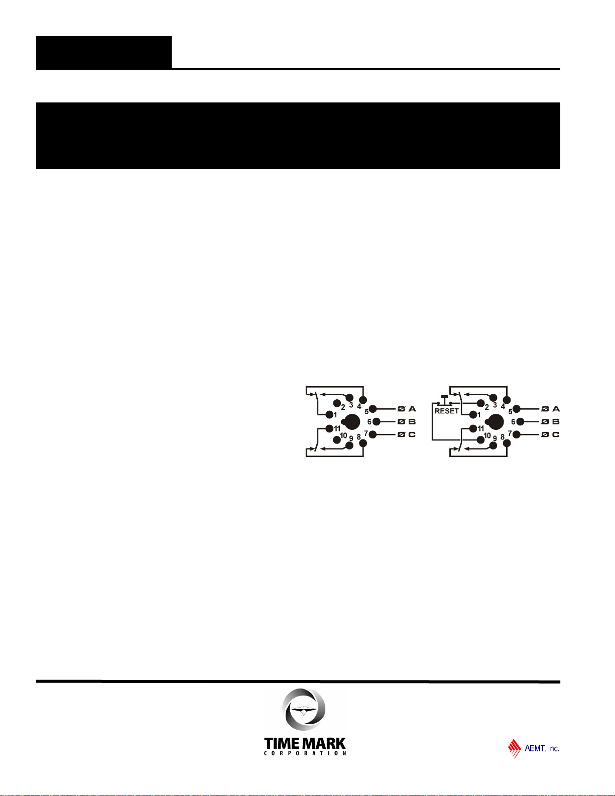
PIN DIAGRAMS
TROUBLESHOOTING
Should the Model 2522 fail to operate properly, check that
all three voltages are present and are of the correct
voltage level and phase rotation (a Model 108A or 108B
phase sequence detector may be used to verify phase
rotation). Check all fuses and verify that all wiring
connections are correct. If problems persist, contact your
local Time Mark Distributor, or the manufacturer at 800-
862-2875.
WARRANTY
The Model 2522 3-Phase Monitor is warranted to be free from
defects in materials and workmanship, and is covered by our
exclusive 5-year Unconditional Warranty. If this device fails to
operate, for any reason, we will repair or replace it free, for five
years from the date of purchase. Contact your local Distributor or
the Time Mark Sales department, Monday through Friday; 8 a.m.
to 5 p.m., CST, for further details.
INSTALLATION
Mount the 11-pin socket in a suitable enclosure.
Connect 3-phase power to terminals 5, 6 and 7 on the
socket. Phase rotation may be verified using a Time Mark
Model 108A or 108B Phase Sequence Detector.
Connect the load control wiring to the appropriate
terminals on the socket:
For motor control applications; use terminals 1 and 3.
For phase loss alarm applications; use terminals 11and 8.
Insert the Model 2522 into the socket and apply power.
If the contacts do not transfer, (green light ON ), check
that all phases are present and of the correct voltage. If
power is correct, rotate the level adjustment counter-
clockwise (CCW). If the contact still does not transfer,
remove power and reverse any two of the three phase
wires at the socket (phase rotation is reversed).
Re-apply power. The contact should transfer to provide a
signal path between pins 1 and 3 and pins 9 and 11. The
green LED should be lit.
NOTE: When installing the Model 2522 monitor in areas of
high humidity or contamination, it is recommended that the
base area and all exposed metal parts of the socket be
coated liberally with a good quality silicon grease, such as
Dow Corning DC-4 or DC-4X. Insert the unit into the socket
and wipe off excess grease around the base. This will prevent
the entrance of moisture and other contaminates into the
base and socket areas.
ADJUSTMENT SETTINGS
The following procedure will allow the Model 2522 to be
adjusted to achieve a trip point just below the nominal
phase-to-phase voltage, where the unit is applied. On
manual reset versions, hold the reset button down
during the following procedure.
MODEL 2522 3-Phase Monitor
READ ALL INSTRUCTIONS BEFORE INSTALLING, OPERATING OR SERVICING THIS DEVICE.
KEEP THIS DATA SHEET FOR FUTURE REFERENCE.
GENERAL SAFETY
POTENTIALLY HAZARDOUS VOLTAGES ARE PRESENT AT THE TERMINALS OF THE MODEL 2522.
ALL ELECTRICAL POWER SHOULD BE REMOVED WHEN CONNECTING OR DISCONNECTING WIRING.
THIS DEVICE SHOULD BE INSTALLED AND SERVICED BY QUALIFIED PERSONNEL.
Installation Instructions
TIME MARK is a division of
Telephone: Main -(918) 438-1220
Sales -(800) 862-2875
Fax: (918) 437-7584
E-mail: sales@time-mark.com
Internet:http://www.time-mark.com
Doc No. 87A382 12/00
© 2000 TIME MARK CORPORATION
11440 East Pine Street
Tulsa, Oklahoma 74116
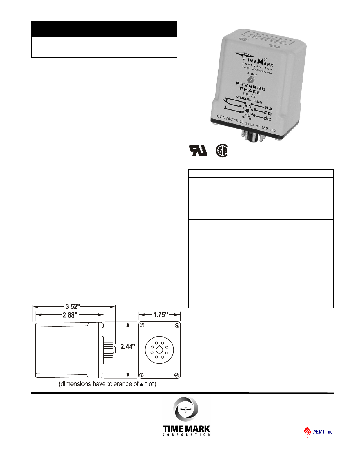
DESCRIPTION
The Model 253 Reverse Phase Relay is a solid-state
sensing device designed for installation in equipment
using 3-phase power. This unit is used where it is
desirable to have a contact closure indicating that the
proper phase rotation sequence has been applied.
The relay closes when the proper sequence (ABC) is
applied, but will remain open if any two phases are
reversed. If reverse phasing occurs during operation,
the relay also de-energizes.
The Model 253 has a special industrial grade relay
designed for low power consumption. The ABC
indicator will be illuminated when the proper phase
rotation sequence is applied.
SPECIFICATIONS
Model 253
Nominal voltage 208 -480 VAC (phase to phase)
Operating range 190 -480 VAC
Frequency 50 to 60 Hz
Power consumption 2W per phase
Transient protection 2500V for 10 msec
Repeat accuracy ± 0.1% (fixed conditions)
Response time .05 seconds
Reset time .05 seconds
Reset type Automatic
Dead Band Approximately 2%
Output contacts SPDT 10A at 240 VAC resistive
Expected relay life Mechanical: 10 million operations
Electrical: 100,000 at rated load
Operating temperature -40° to +131° F
Humidity tolerance 0 -97% w/o condensation
Case material ABS plastic
Mounting 8-pin socket *(order separately)
Weight 6 oz.
Agency approval UL Recognized and CSA Certified
* Order 8-pin socket number 51X120
ll Socket-mounted
ll Senses phase reversal
ll Low power consumption
ll UL Recognized; CSA Certified
MODEL 253
Reverse Phase Relay
TIME MARK is a division of
Telephone: Main -(918) 438-1220
Sales -(800) 862-2875
Fax: (918) 437-7584
E-mail: sales@time-mark.com
Internet:http://www.time-mark.com
Doc No. 87A113 12/00
© 2000 TIME MARK CORPORATION
11440 East Pine Street
Tulsa, Oklahoma 74116
DIMENSIONS
TROUBLESHOOTING
Should the relay fail to operate properly, check that all
three voltages are present and are of the correct level.
Check all fuses and verify that all wiring connections are
correct. Should problems persist, contact the factory for
assistance.
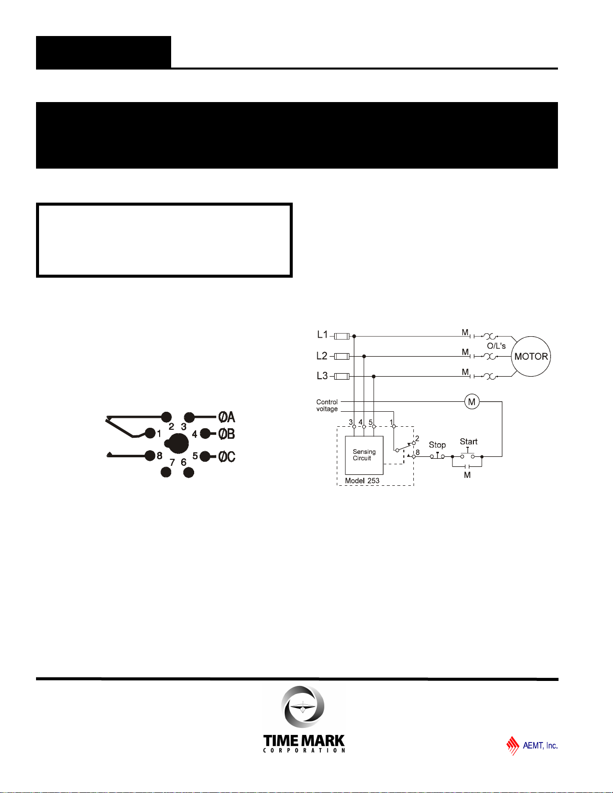
TYPICAL APPLICATION
WARRANTY
The Model 253 Reverse Phase Relay is covered by
Time Mark Corporation’s exclusive 5-Year
Unconditional Warranty. Should this device fail, for
any reason, within five years from the date of purchase,
we will repair or replace it. Contact the Time Mark
Sales department, Monday through Friday; 8 a.m. to 5
p.m., CST, for further details.
MODEL 253Reverse Phase Relay
READ ALL INSTRUCTIONS BEFORE INSTALLING, OPERATING OR SERVICING THIS DEVICE.
KEEP THIS DATA SHEET FOR FUTURE REFERENCE.
GENERAL SAFETY
POTENTIALLY HAZARDOUS VOLTAGES ARE PRESENT AT THE TERMINALS OF THE MODEL 253.
ALL ELECTRICAL POWER SHOULD BE REMOVED WHEN CONNECTING OR DISCONNECTING WIRING.
THIS DEVICE SHOULD BE INSTALLED AND SERVICED BY QUALIFIED PERSONNEL.
Installation Instructions
TIME MARK is a division of
Telephone: Main -(918) 438-1220
Sales -(800) 862-2875
Fax: (918) 437-7584
E-mail: sales@time-mark.com
Internet:http://www.time-mark.com
Doc No. 87A113 12/00
© 2000 TIME MARK CORPORATION
11440 East Pine Street
Tulsa, Oklahoma 74116
Shows No Power Applied
INSTALLATION
Refer to the Pin Drawing below, and on the case of the Model
253. The contacts are shown in the tripped condition.
Connect wiring to the socket as shown (an 8-pin socket, rated
for at least 480 VAC is required).
Refer to the Application Drawing for additional information.
PIN DRAWING
If the relay contacts do not transfer when power is applied
(indicator not lit), check that all three voltages are correct. If
power is present and of the correct voltage, remove power,
then reverse two of the three phase connections at the
socket.
Re-apply power. The contacts should transfer to the normal
condition (pins 1 and 8 closed; indicator lit). There are no
calibrations or adjustments required.
NOTE: When installing the Model 253 monitor in areas of high
humidity or contamination, it is recommended that the base area and
all exposed metal parts of the socket be coated liberally with a good
quality silicon grease, such as Dow Corning DC-4 or DC-4X. Insert
the unit into the socket and wipe off excess grease around the base.
This will prevent the entrance of moisture and other contaminates
into the base and socket areas.
WARNING
IN APPLICATIONS WHERE VOLTAGES IN EXCESS OF
300 VAC ARE TO BE MONITORED, BE CERTAIN TO USE
THE TIME MARK MODEL 51X120 8-PIN SOCKET, OR AN
EQUIVALENT UL APPROVED 600 VAC RATED SOCKET.

DESCRIPTION
The Model 2532 Reverse Phase Relay is designed to
continuously monitor phase rotation of 3-phase lines.
This device should be used in applications where proper
phase rotation is critical, such as fan motors,
compressors, grinders, elevators, etc.
The solid-state sensing circuit drives an internal
electromechanical relay which energizes when power,
with correct phase rotation, is applied.
The relay will not energize if the applied phases are
reversed. It will de-energize if phase rotation is reversed
while the motor is running. An LED indicator will
illuminate with correct ABC phase rotation.
DIMENSIONS
SPECIFICATIONS
Model 2532
Nominal voltage 190-500 VAC (phase to phase)
Frequency 50 to 60 Hz
Power Consumption 2W per phase
Transient protection 2500 VRMS for 10 msec
Repeat accuracy ± 0.1 % (fixed conditions)
Response time .05 seconds
Reset time .05 seconds
Reset type Automatic
Dead band Approximately 2 %
Output contacts SPDT 10A at 240 VAC resistive
Expected relay life Mechanical: 10 million operations
Electrical: 100,000 at rated load
Operating temp -40º to +131º F
Humidity tolerance 0-97 % w/o condensation
Case material ABS plastic
Mounting Surface
Weight 7 oz.
Agency approval UL Recognized and CSA Certified
3.13"
3.5"
2.2" 4.0"
4.8"
lSenses phase reversal on Wye or Delta
l190 to 500 VAC range
lMachine tool case
lUL Recognized & CSA Certified
MODEL 2532
Reverse Phase Relay
TIME MARK is a division of
Telephone: Main -(918) 438-1220
Sales -(800) 862-2875
Fax: (918) 437-7584
E-mail: sales@time-mark.com
Internet:http://www.time-mark.com
Doc No. 87A149 12/00
© 2000 TIME MARK CORPORATION
11440 East Pine Street
Tulsa, Oklahoma 74116
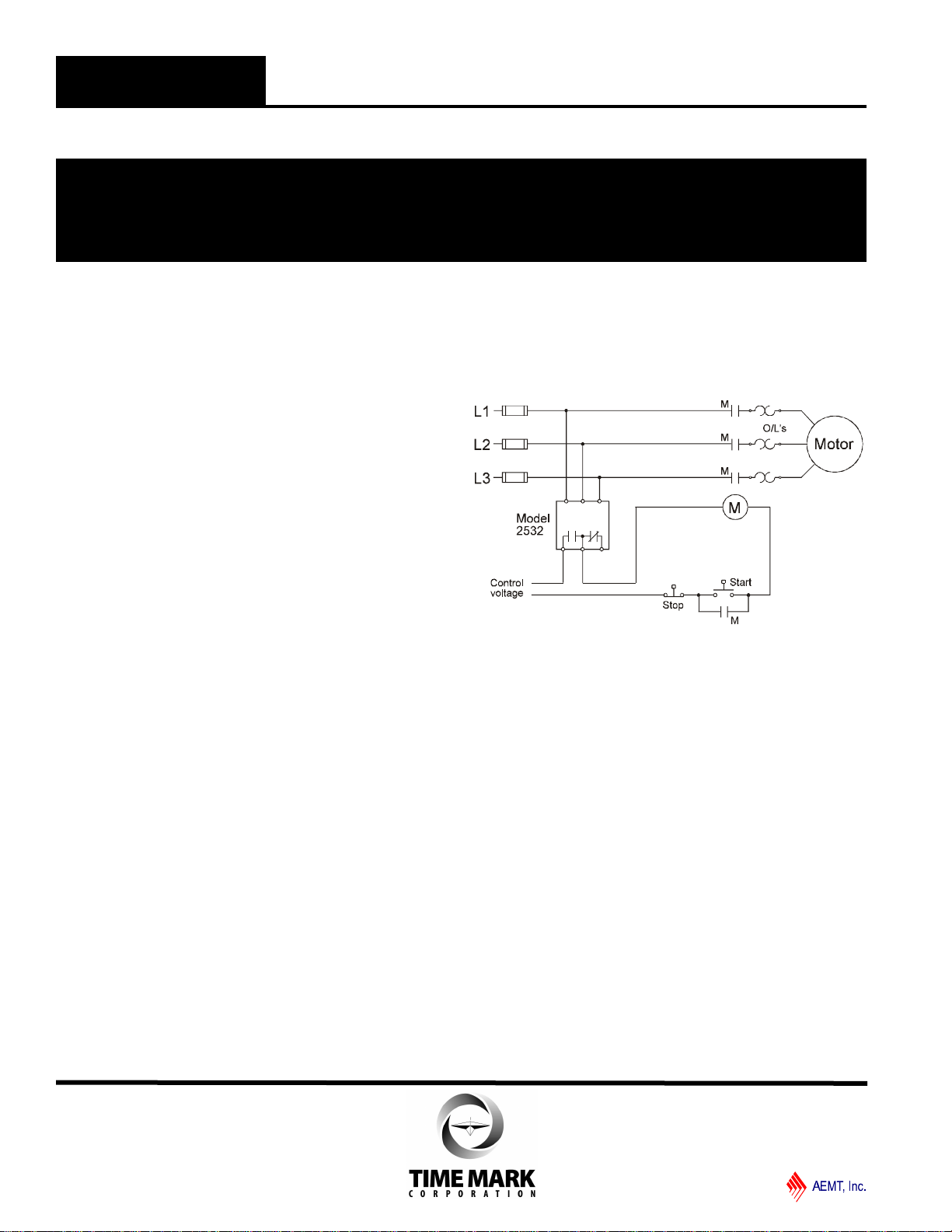
TYPICAL APPLICATION
INSTALLATION
Mount the Model 2532 in the desired location.
Connect the 3-phase power to the terminals marked A,
B, and C.
Connect the control circuit to the terminals with the
contact markings. Refer to the Typical Application
wiring diagram for additional information.
If the relay contacts do not transfer when power is
applied (LED indicator-Off), check that all three
voltages are correct.
If power is present and the voltage is correct, remove
power. Reverse two of the three phase connections.
Re-apply power.
The contacts should transfer to the normal condition
(normally open contacts closed; LED indicator-On).
Calibrations or adjustments are not required.
TROUBLESHOOTING
Should the relay fail to operate properly, check that all
three voltages are present and are of the correct level.
Check all fuses and verify that all wiring connections are
correct. Should problems persist, contact the factory for
assistance.
WARRANTY
The Model 2532 Reverse Phase Relay is covered by
Time Mark Corporation’s exclusive 5-Year
Unconditional Warranty. Should this device fail, for
any reason, within five years from the date of purchase,
we will repair or replace it. Contact the Time Mark
Sales department, Monday through Friday; 8 a.m. to 5
p.m., CST, for further details.
AB
NO NCC
C
MODEL 2532 Reverse Phase Relay
READ ALL INSTRUCTIONS BEFORE INSTALLING, OPERATING OR SERVICING THIS DEVICE.
KEEP THIS DATA SHEET FOR FUTURE REFERENCE.
GENERAL SAFETY
POTENTIALLY HAZARDOUS VOLTAGES ARE PRESENT AT THE TERMINALS OF THE MODEL 2532.
ALL ELECTRICAL POWER SHOULD BE REMOVED WHEN CONNECTING OR DISCONNECTING WIRING.
THIS DEVICE SHOULD BE INSTALLED AND SERVICED BY QUALIFIED PERSONNEL.
Installation Instructions
TIME MARK is a division of
Telephone: Main -(918) 438-1220
Sales -(800) 862-2875
Fax: (918) 437-7584
E-mail: sales@time-mark.com
Internet:http://www.time-mark.com
Doc No. 87A149 12/00
© 2000 TIME MARK CORPORATION
11440 East Pine Street
Tulsa, Oklahoma 74116
DESCRIPTION
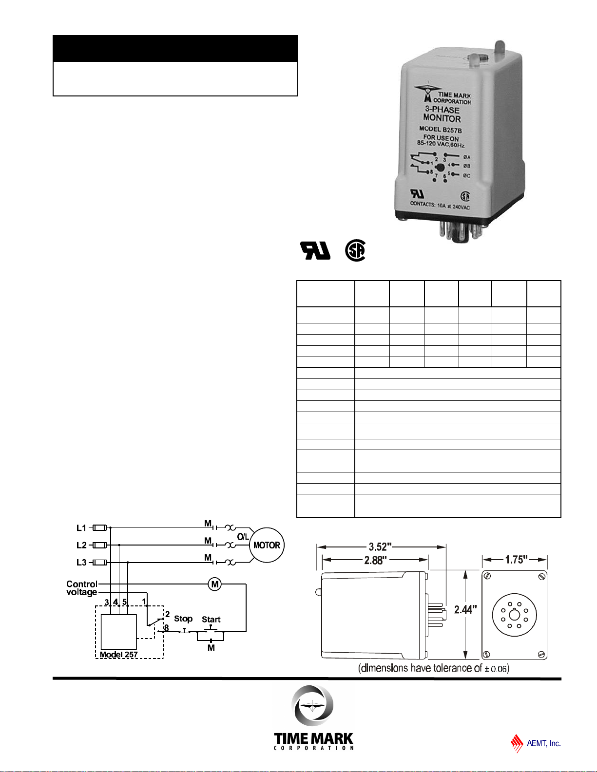
The Model 257 continuously monitors 3-phase power
lines for abnormal conditions. When properly
adjusted, the Model 257 monitor will detect phase
loss on a loaded motor even when regenerated
voltage is present.
This device consists of a solid-state voltage and
phase-angle sensing circuit, driving an electro-
mechanical relay. When correct voltage and phase
rotation are applied, the internal relay will energize.
A fault condition will de-energize the relay. When the
fault is corrected, the monitor will automatically reset
(a manual reset version is also available).
The Model 257 does not require a neutral connection
and can be used with Wye or Delta systems. Voltage
ranges are sufficiently wide to allow for proper
adjustment to existing conditions. Both “TRIP”and
“NORM”condition indicators are provided to aid in
adjustment and system trouble-shooting.
SPECIFICATIONS
AUTO Reset
MANUAL Reset B257B
B257BM 257B
257BM A257B
A257BM EX257B
EX257BM B257B-400
B257BM-
400
257B-400
257BM-400
Nominal AC voltage
(phase to phase) 120 vac 208/240 vac 480 vac 380 vac 120 vac 208/240 vac
Case Color Gray Red Yellow Yellow Gray Red
Adjustment range 85-120vac 160-240vac 380-480vac 300-400vac 85-120vac 160-240vac
Frequency 60 Hz 60 Hz 60 Hz 50 Hz 400 Hz 400 Hz
Power consumption 0.75W 1.5W 4.5W 3.75W 0.75W 1.5W
Transient protection 2500 VAC for 10msec
Repeat accuracy ± 0.1% of set point (fixed conditions)
Response time 50 msec (set or reset)
Dead band Approximately 2%
Output contacts SPDT 10 amps at 240 VAC resistive
Expected relay life Mechanical: 10 million operations
Electrical: 100,000 operations at rated load
Operating temp -40° to +131° F
Humidity tolerance 0 -97% w/o condensation
Enclosure material Dust cover: ABS plastic
Mounting 8-pin socket ( **sold separately)
Weight 5 ounces
Agency approvals UL Recognized* and CSA Certified
*condition of acceptability: the 380V and 480V versions
must be used with a UL Recognized 600 VAC socket
** Order 8-pin socket number 51X120
DIMENSIONS
TYPICAL APPLICATION
ll Detects phase loss, low voltage, phase reversal
ll 50 Hz, 60 Hz and 400 Hz models
ll Automatic or manual reset
ll Five year unconditional warranty
MODEL 257
3-Phase Monitor
TIME MARK is a division of
Telephone: Main -(918) 438-1220
Sales -(800) 862-2875
Fax: (918) 437-7584
E-mail: sales@time-mark.com
Internet:http://www.time-mark.com
Doc No. 87A189 12/00
© 2000 TIME MARK CORPORATION
11440 East Pine Street
Tulsa, Oklahoma 74116
INSTALLATION
Mount the 8-pin socket in a suitable enclosure. A NEMA-1
rated enclosure, designed for socket-mounted relays is
available from Time Mark Corporation.
Connect 3-phase power to terminals 3, 4, and 5 on the
socket. Phase rotation should be verified using a Time Mark
Model 108A or 108B Phase Sequence Detector.
Connect the load control wiring to the appropriate terminals
on the socket:
For motor control applications; use terminals 1 and 8.
For phase loss alarm applications; use terminals 1 and 2.
Insert the Model 257 into the socket and apply power. If the
contact does not transfer (green light ON), check that all
phases are present, and of the correct voltage. If power is
correct, rotate the level adjustment counter-clockwise.
If the contact still does not transfer, remove power and
reverse two of the three phase wires at the socket (phase
rotation is reversed). Re-apply power. The contact should
transfer to provide a signal path between pins 1 and 8.
NOTE: When installing the Model 257 monitor in areas of high
humidity or contamination, it is recommended that the base area
and all exposed metal parts of the socket be coated liberally with
a good quality silicon grease, such as Dow Corning DC-4 or DC-
4X. Insert the unit into the socket and wipe off excess grease
around the base. This will prevent the entrance of moisture and
other contaminates into the base and socket areas.
ADJUSTMENT SETTINGS
The following procedure will allow the Model 257 to be
adjusted to achieve a trip point just below the nominal phase-
to-phase voltage, where the unit is applied.
Rotate the adjustment control fully clockwise, or until the red
(TRIP) indicator illuminates.
Slowly rotate the adjustment control in a counter-clockwise
direction, just until the green (NORM) indicator illuminates.
At this point, the Model 257 is the most sensitive to irregular
power line conditions. If nuisance tripping occurs, turn the
control slightly farther counter-clockwise.
A more accurate setting will require the use of a 3-phase var-
iac to lower the voltage to an exact measurable setting. Time
Mark also offers a factory set version of all models and voltage
ranges, for only a small additional charge.
TROUBLESHOOTING
Should the Model 257 Monitor fail to operate properly, check
that all three voltages are present, and are of the correct
voltage level and phase rotation (a Model 108A or 108B
Phase Sequence Detector should be used to verify phase
rotation). Check all fuses and verify that all wiring connections
are correct. If problems persist, contact your local Time Mark
Distribuor, or the factory for assistance (Monday-Friday, 8 a.
m. to 5 p.m. CST).
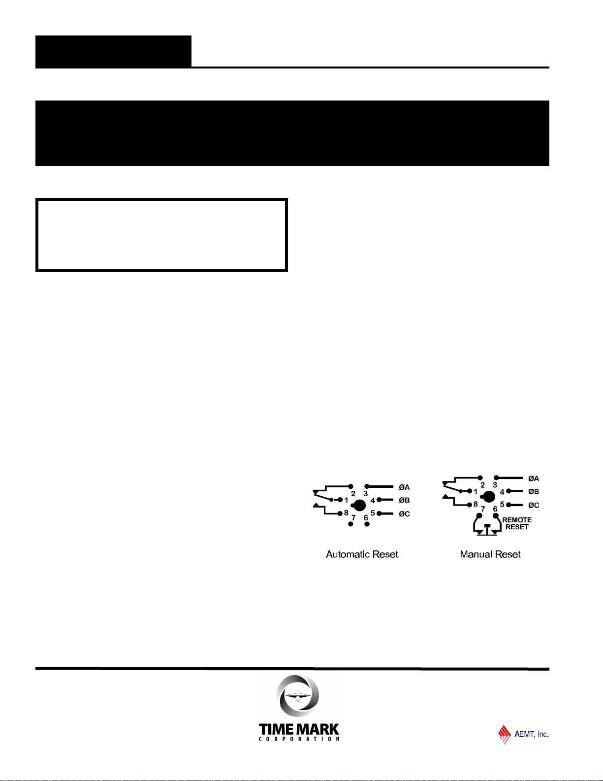
MANUAL RESET VERSIONS
IF YOU DO NOT WISH TO USE THE EXTERNAL RESET
SWITCH ON THE MANUAL RESET VERSION, YOU MUST
JUMPER PINS 6 AND 7. Refer to the Manual Reset 8-pin
diagram.
WARRANTY
The Model 257 3-Phase Monitor is warranted to be free from
defects in materials and workmanship, and is covered by our
exclusive 5-year Unconditional Warranty. If this device fails
to operate, for any reason, we will repair or replace it free, for
five years from the date of purchase. Contact the Time Mark
Sales department, Monday through Friday; 8 a.m. to 5 p.m.,
CST, for further details.
MODEL 257 3-Phase Monitor
READ ALL INSTRUCTIONS BEFORE INSTALLING, OPERATING OR SERVICING THIS DEVICE.
KEEP THIS DATA SHEET FOR FUTURE REFERENCE.
GENERAL SAFETY
POTENTIALLY HAZARDOUS VOLTAGES ARE PRESENT AT THE TERMINALS OF THE MODEL 257.
ALL ELECTRICAL POWER SHOULD BE REMOVED WHEN CONNECTING OR DISCONNECTING WIRING.
THIS DEVICE SHOULD BE INSTALLED AND SERVICED BY QUALIFIED PERSONNEL.
Installation Instructions
TIME MARK is a division of
Telephone: Main -(918) 438-1220
Sales -(800) 862-2875
Fax: (918) 437-7584
E-mail: sales@time-mark.com
Internet:http://www.time-mark.com
Doc No. 87A189 12/00
© 2000 TIME MARK CORPORATION
11440 East Pine Street
Tulsa, Oklahoma 74116
WARNING
IN APPLICATIONS WHERE VOLTAGES IN EXCESS OF
300 VAC ARE TO BE MONITORED, BE CERTAIN TO USE
THE TIME MARK MODEL 51X120 8-PIN SOCKET, OR AN
EQUIVALENT UL APPROVED 600 VAC RATED SOCKET.

DESCRIPTION
The Model 258 continuously monitors 3-phase power
lines for abnormal conditions. When properly ad-
justed, the Model 258 Monitor will detect phase loss
on a loaded motor even when regenerated voltage is
present.
This device consists of a solid-state voltage and
phase-angle sensing circuit, driving an electro-
mechanical relay. When correct voltage and phase
rotation are applied, the internal relay will energize.
A fault condition will de-energize the relay. When the
fault is corrected, the monitor will automatically reset
(a manual reset version is also available).
The Model 258 3-Phase Monitor does not require a
neutral connection and can be used with Wye or
Delta systems. Voltage ranges are sufficiently wide
to allow for proper adjustment to existing conditions.
Both “TRIP” and “NORM” condition indicators are
provided to aid in adjustment and system trouble-
shooting.
TYPICAL APPLICATION
SPECIFICATIONS
AUTO Reset
MANUAL Reset B258B
B258BM 258B
258BM A258B
A258BM EX258B
EX258BM B258B-400
B258BM-400 258B-400
258BM-400
Nominal AC voltage
(phase to phase) 120 vac 208/240 vac 480 vac 380 vac 120 vac 208/240 vac
Case Color Gray Red Yellow Yellow Gray Red
Adjustment range 85-120 vac 160-240 vac 380-480 vac300-400 vac 85-120 vac 160-240 vac
Frequency 60 Hz 60 Hz 60 Hz 50 Hz 400 Hz 400 Hz
Pwr consumption 0.75W 1.5W 4.5W 3.75W 0.75W 1.5W
Transient protection 2500 VAC for 10 ms
Repeat accuracy ± 0.1% of set point (fixed conditions)
Response time 50 msec (set or reset)
Dead band Approx. 2%
Output contacts SPDT 10 amps at 240 VAC resistive
Expected relay life Mechanical: 10 million operations
Electrical: 100,000 operations at rated load
Operating temp. -40° to +131° F
Humidity tolerance 0 -97% w/o condensation
Enclosure material Dust cover: ABS plastic
Mounting 8-pin socket ( **sold separately)
Weight 5 oz.
Agency approvals UL Recognized* and CSA Certified
*condition of acceptability: the 380V and 480V versions
must be used with a UL Recognized 600 VAC socket
** Order 8-pin socket number 51X120
DIMENSIONS
ll Detects phase loss, low voltage, phase reversal
ll 50 Hz, 60 Hz and 400 Hz models
ll Automatic or manual reset
ll Five year unconditional warranty
MODEL 258
3-Phase Monitor
TIME MARK is a division of
Telephone: Main -(918) 438-1220
Sales -(800) 862-2875
Fax: (918) 437-7584
E-mail: sales@time-mark.com
Internet:http://www.time-mark.com
Doc No. 87A123 12/00
© 2000 TIME MARK CORPORATION
11440 East Pine Street
Tulsa, Oklahoma 74116
Slowly rotate the adjustment control in a counter-clockwise
direction, just until the green (NORM) indicator illuminates.
At this point, the Model 258 is the most sensitive to irregular
power line conditions. If nuisance tripping occurs, turn the
control slightly farther counter-clockwise.
A more accurate setting will require the use of a 3-phase
variac to lower the voltage to an exact measurable setting.
Time Mark also offers a factory set version of all models and
voltage ranges, for only a small additional charge.
TROUBLESHOOTING
Should the Model 258 Monitor fail to operate properly, check
that all three voltages are present, and are of the correct
voltage level and phase rotation (a Model 108A or 108B
Phase Sequence Detector should be used to verify phase
rotation). Check all fuses and verify that all wiring connections
are correct. If problems persist, contact your local Time Mark
Distributor, or the factory for assistance (Monday-Friday, 8 a.
m. to 5 p.m. CST).
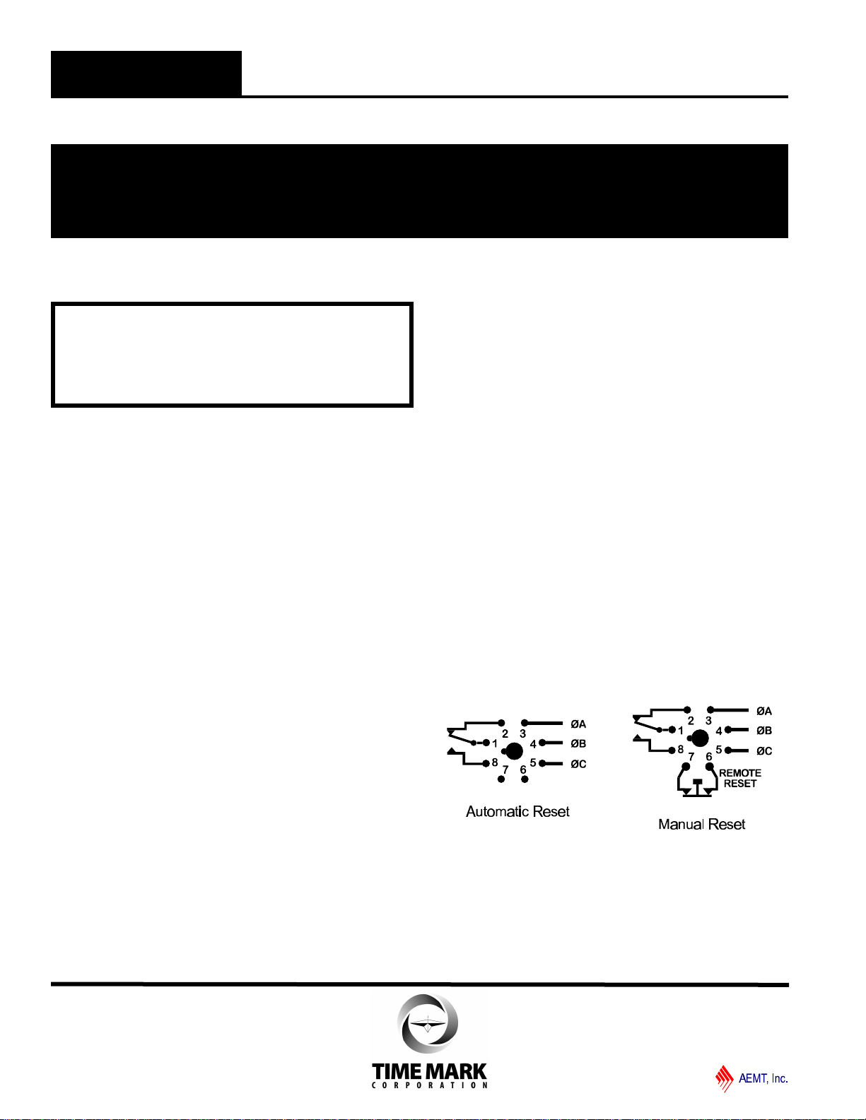
MANUAL RESET VERSIONS
IF YOU DO NOT WISH TO USE A NORMALLY CLOSED
EXTERNAL RESET SWITCH ON THE MANUAL RESET
VERSION, YOU MUST JUMPER PINS 6 AND 7. Refer to
the Manual Reset 8-pin diagram.
WARRANTY
The Model 258 3-Phase Monitor is warranted to be free from
defects in materials and workmanship, and is covered by our
exclusive 5-year Unconditional Warranty. If this device fails
to operate, for any reason, we will repair or replace it free, for
five years from the date of purchase. Contact the Time Mark
Sales department for further details.
INSTALLATION
Mount the 8-pin socket in a suitable enclosure. A NEMA-1
rated enclosure, designed for socket-mounted relays is
available from Time Mark Corporation.
Connect 3-phase power to terminals 3, 4, and 5 on the
socket. Phase rotation should be verified using a Time Mark
Model 108A or 108B Phase Sequence Detector.
Connect the load control wiring to the appropriate terminals
on the socket:
For motor control applications; use terminals 1 and 8.
For phase loss alarm applications; use terminals 1 and 2.
Insert the Model 258 into the socket and apply power. If the
contact does not transfer (green light ON), check that all
phases are present, and of the correct voltage. If power is
correct, rotate the level adjustment counter-clockwise.
If the contact still does not transfer, remove power and
reverse any two of the three phase wires at the socket (phase
rotation is reversed). Re-apply power. The contact should
transfer to provide a signal path between pins 1 and 8.
NOTE: When installing the Model 258 monitor in areas of high
humidity or contamination, it is recommended that the base area
and all exposed metal parts of the socket be coated liberally with
a good quality silicon grease, such as Dow Corning DC-4 or DC-
4X. Insert the unit into the socket and wipe off excess grease
around the base. This will prevent the entrance of moisture and
other contaminates into the base and socket areas.
ADJUSTMENT SETTINGS
The following procedure will allow the Model 258 to be
adjusted to achieve a trip point just below the nominal phase-
to-phase voltage, where the unit is applied.
Rotate the adjustment control fully clockwise, or until the red
(TRIP) indicator illuminates.
WARNING
IN APPLICATIONS WHERE VOLTAGES IN EXCESS OF
300 VAC ARE TO BE MONITORED, BE CERTAIN TO USE
THE TIME MARK MODEL 51X120 8-PIN SOCKET, OR AN
EQUIVALENT UL APPROVED 600 VAC RATED SOCKET.
MODEL 258 3-Phase Monitor
READ ALL INSTRUCTIONS BEFORE INSTALLING, OPERATING OR SERVICING THIS DEVICE.
KEEP THIS DATA SHEET FOR FUTURE REFERENCE.
GENERAL SAFETY
POTENTIALLY HAZARDOUS VOLTAGES ARE PRESENT AT THE TERMINALS OF THE MODEL 258.
ALL ELECTRICAL POWER SHOULD BE REMOVED WHEN CONNECTING OR DISCONNECTING WIRING.
THIS DEVICE SHOULD BE INSTALLED AND SERVICED BY QUALIFIED PERSONNEL.
Installation Instructions
TIME MARK is a division of
Telephone: Main -(918) 438-1220
Sales -(800) 862-2875
Fax: (918) 437-7584
E-mail: sales@time-mark.com
Internet:http://www.time-mark.com
Doc No. 87A123 12/00
© 2000 TIME MARK CORPORATION
11440 East Pine Street
Tulsa, Oklahoma 74116
This manual suits for next models
137
Table of contents


