Time TH170 User manual

INTEGRATED HARDNESS TESTER
TH170
Instruction Manual
TIME Group Inc.

CONTENTS
1 Introduction…………………………………………………………..…………… 1
1.1 Features……………………………………………….………….……..…..…… 1
1.2 Main application and testing range…………………………….…..………..… 1
1.3 Specification..……………………………………………….……….………...… 2
1.4 Working condition……………………………………………….….…...……… 3
2Structure feature & testing principle………………………..….….……………. 4
2.1 Structure feature…………………………………………………..……..…...… 4
2.2 Testing principle……………………………………………………..…..……… 5
3 Specialties…………………..………………….……………….……..…………… 5
3.1 Specifications………………………………………………….…….……..….… 6
3.2 Dimension and weight……………………………………………..…………..…7
4 Using……………………..………………………………….………..……………. 7
4.1 Preparation before using…………………………………………..…………… 7
4.2 Testing…………………………………………………………………..…..…… 8
5 Special prompt……………………...…………………….……………..……...… 9
6Operation explain in details………………………………….….……..………… 9
6.1 Switch on…………………………………………….………….……..…....…… 9
6.2 Measuring operation……………………………………………..……….…… 10
6.3 Key-press operation……………………………………………….………...… 10
6.4 Switch off……………………………………………….……………...….…… 10
6.5 Menu structure…………………………………………...……..……..……… 10
6.6 Common function………………………………………………..……..……… 12

6.7 Memory manager………………………………………………..……..……… 13
6.8 Test setting…………………………………………………………..…….....… 14
6.9 System setting……………………………………………………………….…. 17
6.10 Software……………………………………………………………..…………18
6.11 Software calibration……………………………………….………..…………18
6.12 Battery replacement…………………………………….….……….…………19
6.13 Backlight………………………………………………………..….…………..20
6.14 Auto Power Off…………………………………………………….………….20
6.15 Connection of data transmission cable……………….………………………20
7Maintenance and repair…………………………….…………………………… 20
7.1 Impact device………………………………………….……………..………… 20
7.2 Repair………………………………………………………....………...……… 20
8Inspection periods………………...…………………..……….………………… 20
9Notice for uses……………………...……………………………..….…..…….… 20
10 Notice of transportation and storage………………………..……………………21

1 Introduction
1.1 Features
zLCD display 128×32 dot matrix;
zUSB communication interface;
zImpact direction automatically identifying;
zMemory 270 average data in 9 files ;
zUpper and lower limit pre-setting;
zBattery capacity display and power off automatically lack of voltage;
zBacklight for convenient use in darkness;
zSoftware calibration;
zAAA 1.5V(7#)battery 2 pc;
zComputer software available.
1.2 Main application and testing range
1.2.1 Main application
zThe installed machinery and permanently assembled parts;
zDie cavity of moulds;
zHeavy and large work piece;
zFailure analysis of pressure vessel, steam turboset and other equipment;
zNarrow space workpiece;
zAxletree and other spare parts;
zMaterial identification of the metal material warehouse;
zQuick inspection for large workpiece;
zOthers.
1.2.2 Testing range
See table 1.

Table 1
Material Hardness scale Application range
HRC 20.0~68.4
HRB 38.4~99.8
HB 81~654
HV 81~955
Steel and Cast Steel
HS 32.5~99.5
HRC 20.4~67.1
Cold Work Tool Steel HV 80~898
HRB 46.5~101.7
HB 85~655
Stainless Steel
HV 85~802
Grey Cast Iron HB 93~334
Nodular Cast Iron HB 131~387
HB 19~164
Cast Aluminum Alloys HRB 23.8~84.6
HB 40~173
Copper-Zinc Alloys HRB 13.5~95.3
Copper-Aluminum Alloys HB 60~290
Wrought Copper HB 45~315
1.3 Specification
1.3.1 Standard delivery
TH170 Main Unit 1
AAA 1.5V(7#) battery 2
Smallsupportingring 1
Cleaning brush 1
Hardness test block(760±30HLD)1
USB communication cable 1
Drivingdiskforcomputer 1
1.3.2 Optional parts
DataView for TH170;
Supporting rings,see table 2.

Table 2
No. Code Model Sketch Remarks
1 03-03.7 Z10-15 For testing cylindrical outside
surface R10-R15
2 03-03.8 Z14.5-30 For testing cylindrical outside
surface R14.5-R30
3 03-03.9 Z25-50
For testing cylindrical outside
surface R25-R50
4 03-03.10 HZ11-13 For testing cylindrical inside
surface R11-R13
5 03-03.11 HZ12.5-17 For testing cylindrical inside
surface R12.5-R17
6 03-03.12 HZ16.5-30
For testing cylindrical inside
surface R16.5-R30
7 03-03.13 K10-15
For testing spherical outside
surface SR10-SR15
8 03-03.14 K14.5-30
For testing spherical outside
surface SR14.5-SR30
9 03-03.15 HK11-13 For testing spherical inside
surface SR11-SR13
10 03-03.16 HK12.5-17 For testing spherical inside
surface SR12.5-SR17
11 03-03.17 HK16.5-30
For testing spherical inside
surface SR16.5-SR30

12
03-03.18 UN
For testing cylindrical outside
Surface , radius adjustable
R10~∞
1.4 Working condition
Environmental temperature:0℃~40℃;
Relative humidity: ≤90 %;
The surrounding environment should be no vibration, strong magnetic field, corrosive
medium and heavy dust.
2 Structure feature & testing principle
2.1 Structure feature
Structure feature see figure 1.

TIME Group Inc.
Hardness Tester TH170
MODLE
HARDNESS TESTER
BATTERY
GROUP INC.
AAA 1.5V X 2
TH170
USB
HARDNESS TESTER
TH170MODLE
BATTERY
AAA 1.5V X 2
GROUP INC.
Figure 1
2.2 Working principle
The basic principle is: The impact object of certain weight pounds at the testing surface under
certain test force. Measure the impacting velocity and the rebounding velocity of the impact object
respectively when it is 1mm above the testing surface. The calculation formula is as followed:
HL=1000×VB/ VA

Where, HL--Leeb hardness value
VB-- Rebounding velocity of the impact object
VA --Impacting velocity of the impact object
3 Specialties
3.1 Specifications
3.1.1Impact Device:D;
3.1.2 Features of Impact Device and testing demand see table 3,indentation dimension of test tip
see table 4;
Table 3
Parameter Value
Impact energy 11mJ
Impact object weight 5.5g
Hardness of test tip ≥1600HV
Diameter of test tip 3mm
Material of test tip Tungsten Carbide
Max. hardness of workpiece 940HV
Roughness of workpiece Ra ≤1.6μm
Min. weight of workpiece
Test directly >5kg
Need stable support 2~5kg
Need couplant 0.05~2kg
Min thickness of workpiece
Test directly >5mm
Need couplant ≤5mm
Min. depth of harden surface 0.8mm
Table 4
Hardness
(HV)
Parameter Value(mm)
Indentation diameter 0.54
300 Indentation depth 0.024
Indentation diameter 0.54
600 Indentation depth 0.017
Indentation diameter 0.35
800 Indentation depth 0.010
3.1.3 Accuracy and repeatability of displayed value see table 5.
Table 5

Hardness value of Leeb
standard test block
Error of
displayed value
Repeatability of
displayed value
760±30HLD ±6 HLD 10 HLD
530±40HLD ±10 HLD 10 HLD
3.1.4 Measuring range:170~960HLD;
3.1.5 Measuring direction:360°;
3.1.6 Scales:HL、HB、HRB、HRC、HV、HS;
3.1.7 Display:128×32 dot matrix LCD;
3.1.8 Data memory:270 average data in 9 files;
3.1.9 Upper and lower limit setting:same to measuring range;
3.1.10 Power:AAA(7#)1.5V 2pc;
3.1.11 Continual working time :about 150 hours(without backlight);
3.1.12 Communication interface:USB2.0.
3.2 Dimension and weight
3.2.1 Dimension:155mm×55mm×25mm
3.2.2 Weight: about 166g.
4 Using
4.1 Preparation before using
4.1.1Preparation for sample surface
Preparation for sample surface should conform to the relative requirement in figure 3.
●In the preparation process for sample surface, the hardness effect of being heated or cold
processing on the surface of sample should be avoided;
●Too big roughness of the measured surface could cause measure error. So, the measured surface
must be metallic luster, smoothing and polish, without oil stain;
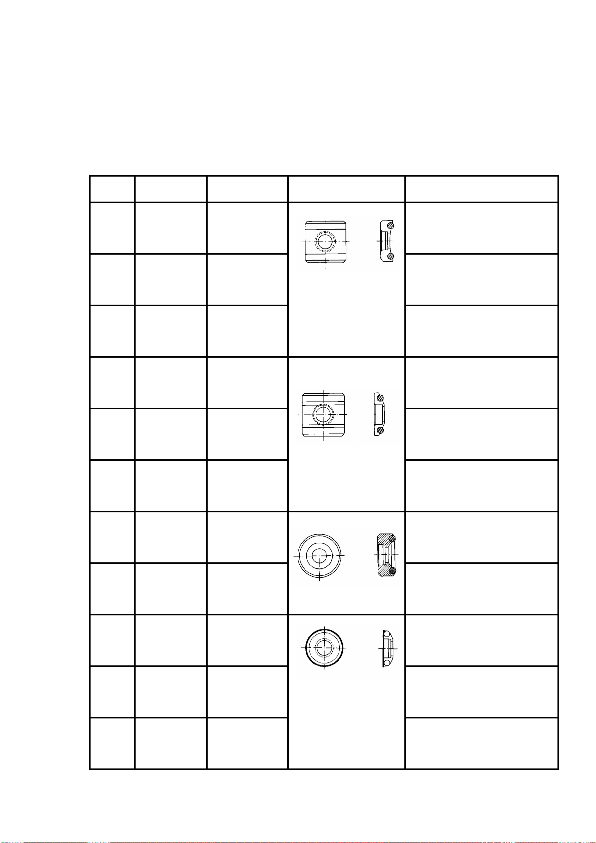
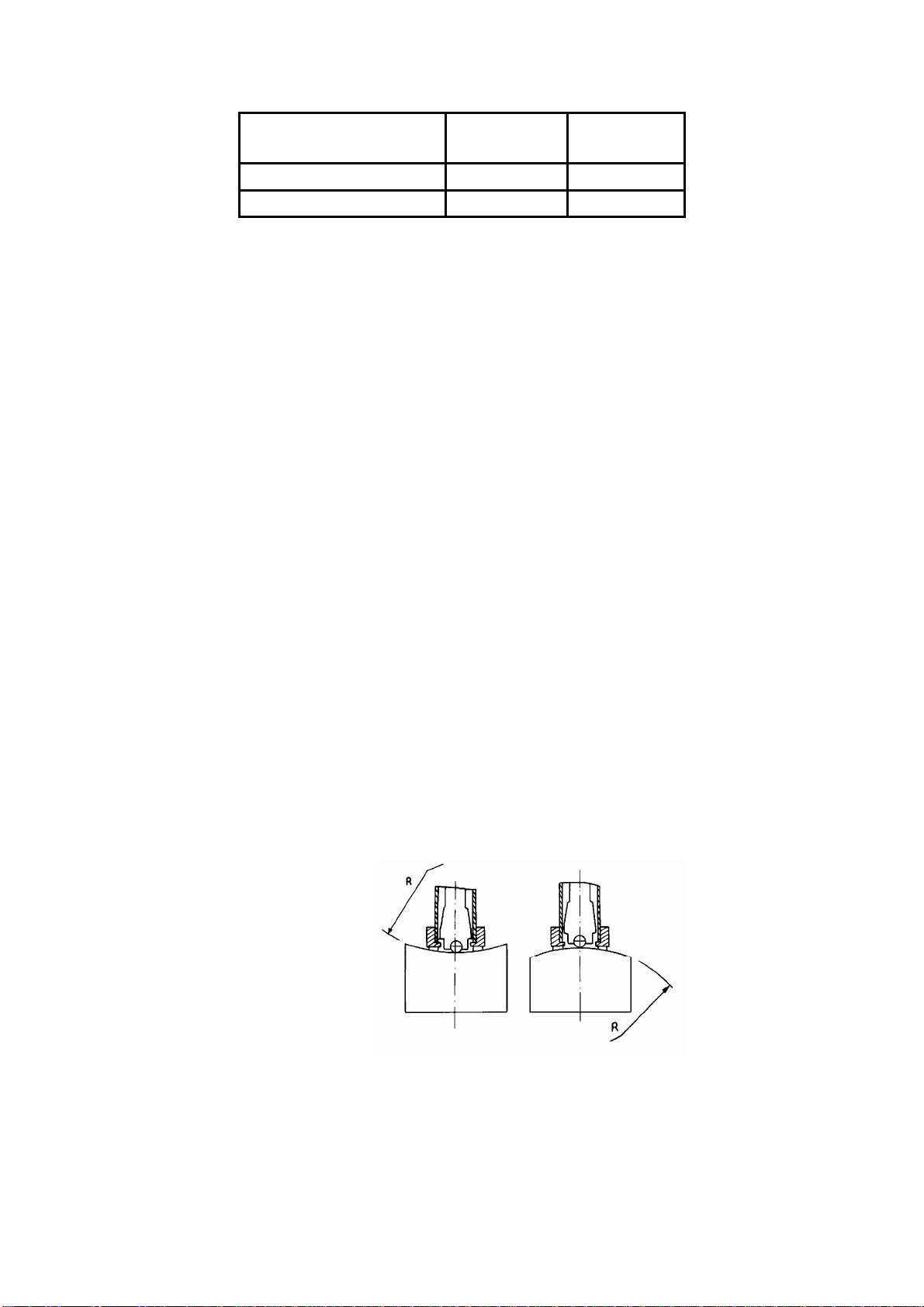
●Curved surface: The best testing surface of sample is flat. When the curvature radius R of the
surface to be tested is smaller than 30mm,the small support ring or the shaped support rings
should be chosen, see figure 2.
Figure 2
●Support of test sample
Support is not necessary for heavy sample.
Medium-weight parts must be set on the smoothing and stable plane. The sample must set

absolutely equability and without any wobble.
●The sample should have enough thickness, minimum thickness of sample should conform to
table 3.
●For the sample with hardened layer on surface, the depth of hardened layer should conform to
table 3.
●Coupling
Light-weight sample must be firmly coupled with a heavy base plate. Both coupled surfaces must
be flat and smooth. And there should be no redundant coupling agent exists. The impact direction
must be vertical to the coupled surface.
●When the sample is a big plate, long rod or bending piece, it can be deformed and become
unstable, even though its weight and thickness is big enough, and accordingly, the test value may
not be accurate. So should be reinforced or supported at its back.
●Magnetism of the sample itself should be avoided.
4.1.2 Preset test parameters
See 6.8.
4.2 Testing
zThe instrument can be calibrated with standard test block, the accuracy and repeatability
displayed should be within the regulation of table 5.
4.2.1 Loading
zPut the supporting ring onto the surface of workpiece,hold the concave area by left
hand,and press down the body by right hand while holding the loading key;
zImpact direction should be vertical to tested surface.
4.2.2 Testing
zPress release button at top of the main unit to test. The sample and the main unit as well
as the operator are all required being stable;
zUsually, test 5 times on each measure area of sample. The data dispersion should not be
more than mean value±15HL;
zThe distance between any two indentations or from the center of any indentation to the
edge of tested sample should conform to the regulation of table 6;
Table 6
Distance between any two indentations
(mm)Indentation to the edge of tested sample
(mm)
≥3 ≥5
zFor special material, if accurate conversion from the Leeb hardness into other
hardness method is wanted, contrastive test must be done to get conversion relations. Use
inspected qualified Leeb hardness tester and corresponding other hardness tester to test at
same sample respectively. For each hardness value, measure 5 Leeb hardness values. using
Leeb hardness arithmetic average value and corresponding hardness method average value
as correlative value to make individual hardness contrastive curve,see figure 3.

A1 A2 A3 A4 A5
A1-A5: Hardness samples
“ ”: Impress of hardness scales to be converted
“ ”: Impress of HL hardness scales
Figure 3
4.2.3 Testing result
zIn front of Leeb hardness symbol HL, expresses the hardness value; behind HL
expresses type of impact device. For example: 700HLD expresses using D type of impact device
measured Leeb hardness value is 700;
zFor other hardness method converted from Leeb hardness, put the symbol of
corresponding hardness method in front of Leeb hardness symbol. For example: 400HVHLD
expresses using D type of impact device measured Leeb hardness value converted Vickers
hardness value is 400.
5 Special prompt
zIn normal condition, it could not memory present testing value while not reaching
impact times which has been set. If want to memory, press 【Cal. Average】at the main display
interface to end the testing in advance and then memory;
zWhen using the function of 【Cal. Average】to end the testing in advance, the function
of 【Auto Save】、【Auto Trans.】etc. will not work;
zNot all hardness methods can be converted to each other for all materials(See table 1).
The setting of hardness scale will recover to HL automatically after material setting is changed. So
select 【Material】first then select 【Hardness Scale】when setting measure condition.
6 Operation explain in details
6.1 Switch on
Press to switch on,the screen will show as follows in 2 seconds:
TH170
TIME Group Inc.

Then it enters the main display interface,see figure 4.
Figure 4
Instruction of the main display interface:
Measured value
:
Display present single time measured value (without average value indicator),
or display the present average value (with average value indicator).
Display ↑means over conversion or measured range, ↓means lower than conversion or measured
range.
Impact times
:
Display the times that have been impacted, the according times will be
displayed in reverse video when browsing single measured value.
Average value indicator
:
After reaching the preset impact times, It appears to show the mean
value.
Hardness scale
:
Show the present hardness scale that has been selected.
Impact direction
:
Show the present impact direction that has been selected.
Battery info
:
Show the rest capacity of battery.
Over tolerance alarm
:
It will display as
when the present measured single value or
average value is
within the tolerance range,otherwise it will display as .
Lower tolerance alarm
:
It will display as when the present measured single value or
average value is within the tolerance range,otherwise it will display as .
6.2 Measuring operation
The screen will display each measured value during each measurement under the measuring
Hardness
scale
Average value
indicator
Impact
direction
Battery info.Impact times
Measured
value
Lower tolerance
alarm
Over tolerance
alarm

display interface, and the impact times add 1 accordingly;if the measured value is beyond
tolerance range,the according mark will change to solid mark;the average value will be
displayed in 2 seconds when reaching the impact times.
6.3 Key-press operation
zPress or to browse singe measured value,the impact times will be
displayed in reverse video;
zPress to enter the menu.
6.4 Switch off
Press to switch off.
6.5 Menu structure
Preset tester parameters and the additional functions can be performed by the menu operation. At
the main display interface, press toenterthemainmenu.

zFor convenient operation, the common function such as “Save Average”、“Delete
Single”、“Cal. Average”、“Backlight On(Off)”,have been put into main display interface;
zThe main display interface have the key 【Exit】,it is convenient to return to measuring
display interface;
zPress 【Exit】key will return to measuring display interface after using common
function and setting function;
Main display
interface
Save Average
Delete Single
Cal. Average
Memory Manager
Backlight On(Off)
Test Set
System Set
About Software
Exit
Auto Save On(Off)
Auto Delete On(Off)
Auto Trans. Off
LCD Brightness
Exit
Impact Direc.
Average
Material
Hardness Scale
Tolerance Limit
Exit
View File
Delete File
Select Save File
Transfer
Exit

zPress or can choose all function and sub-menu circularly ,
press to choose the underside function or sub-menu and then press , the cursor
will skip to the topside function or sub-menu,press to choose the topside function or
sub-menu and then press , the cursor will skip to the underside function or sub-menu.
6.6 Common function
Press to enter the main menu under measuring display interface.
Press or to move the cursor to
demanded function and press to confirm.
Note
:
Press or to see pale
letter
。
Save Average:Memory the present average value.
Delete Single
Cal. Average
Memory Manager
Backlight On
Test Set
System Set
About Software
Exit
Save Avera
g
e

Note
:
The memory can not be processed under the both position of not
reaching preset impact times and not choosing
“
Cal.
Average
”
.
Delete Single:Delete the last measured value;Delete the certain measured value when
browsing the single measured value;Delete the last single measured value when displaying
average value.
Note
:
Please move the cursor to
“
YES
”
or
“
NO
”
and press to
confirm when delete.
Cal. Average:Display the average measured value when impact times have not reached
preset times.
Backlight On(Off):“Backlight On”will be displayed when choosing the backlight;
“Backlight Off”will be displayed when not choosing the backlight.
Note
:
Press any one of the keys 、、when switch on
the backlight will be chose.
6.7 Memory manager
The instrument includes 9 files and each one can memory 30 measured average value. You
can choose another file to memory when 30 measured average value is stored,
Press to enter the main menu when on measuring display interface.
Press 、to move the cursor to
【Memory Manager 】, press enter
【Memory Manager】.
Note
:
The pale letter can be seen by
pressing 、.
Save Average
Delete Single
Cal. Average
Backlight On
Test Set
System Set
About Software
Exit
Memor
y
Mana
g
e
r

Press 、to move the cursor to
certain function key and press .
Note
:
The pale letter can be seen by
pressing 、.
6.7.1 Browsing file
Firstly please choose the file number to be browsed.
Press 、to choose the file
number.
Press to confirm.
Press 、to turn the page.
Press return to【Memory Manager】.
6.7.2 Delete file
Firstly please choose the file number to be deleted.
Press 、to choose the file
number.
Press enter confirm delete interface.
Press 、to choose.
Delete File
Select Save File
Transfer
Exit
View File
File No.: 1
No.01 789HL
No.02 517HL
No.03 788HL
No.04 522HL
File No.: 1
Confirm Delete
NO
YES

Press to confirm and return to【Memory
Manager】.
6.7.3 Memory file choosing
Choose the file number for memory.
Press 、to choose the file
number.
Press to confirm and return to measuring
display interface.
6.7.4 Data communication
The memory value can be transmitted out via USB interface,see 6.15.
6.8 Test setting
Press to enter the main menu under measuring display interface.
Press 、to move the cursor
to 【Test Set】and press .
Note
:
The pale letter can be seen by
pressing
、.
Press 、to move the cursor
to certain function and press .
Avera
g
e
Material
Hardness Scale
Tolerance Limit
File No.: 1
Save Average
Delete Single
Cal. Average
Memory Manager
Backlight On
System Set
About Software
Exit
Test Set
Im
p
act Direc.

Note
:
The pale letter can be seen by
pressing
、
.
6.8.1 Impact direction setting
Press 、to move the
cursor to certain direction to be set.
Press to finish the set and return to
measuring display interface.
If preset impact direction to ,the instrument can identify the impact direction and correct
the wrong direction automatically. Both directions of and are different and need to be
confirmed by hand.
Press 、to move the cursor
to correct impact direction.
Press to confirm.
The indication of different direction displays
is caused of shaking of impact device.
6.8.2 Mean times setting
The mean times can be modified from 1 to
10.
Press 、to modify.
Press to finish set and return to
measuring display interface.
6.8.3 Material setting
Press 、to move the cursor
to certain material to be set.
Press to finish set and return to
measuring display interface.
Note 1.The hardness scale will come
CWT. Steel
STAIN. Steel
GC. Iron
N
c.Iron
Cast Alumin
Copper-Zinc
Copper-Alumin
Mean Times:
10
(
Cast
)
Steel
Confirm Direc.
Table of contents
Popular Test Equipment manuals by other brands

PCB Piezotronics
PCB Piezotronics 498A-0010 Installation and operating manual

Gerus
Gerus GERUTEST NTB5 Operation manual

Crane Electronics
Crane Electronics ReadStar TT quick start guide

Bante Instruments
Bante Instruments ECscan40 instruction manual

Witschi
Witschi ANALYZER Q1 instruction manual

HP
HP 37717C Calibration manual