134
2
Warranty
Warranty malfunctions occurring under conditions of normal use
in conformity with the Instruction Manual and Product Precau-
tionary Markings will be repaired free of charge. This warranty
is valid for a period of three (3) years from the date of purchase.
Please contact the distributor from which you purchased the
product for further information on warranty provisions.
Introduction
Thank you for purchasing the HIOKI Model 3244-60CARD HiT-
ESTER. To obtain maximum performance from the instrument,
please read this manual first, and keep it handy for future refer-
ence.
The 3244-60 is a card-shaped digital multimeter designed to
measure DC/AC voltage and resistance, and Continuity check.
Initial Inspection
When you receive the instrument, inspect it carefully to ensure
that no damage occurred during shipping. If damage is evident,
or if it fails to operate according to the specifications, contact
your dealer or Hioki representative.
Maintenance and Service
• To clean the instrument, wipe it gently with a soft cloth moist-
ened with water or mild detergent. Never use solvents such
as benzene, alcohol, acetone, ether, ketones, thinners or
gasoline, as they can deform and discolor the case.
• If the instrument seems to be malfunctioning, contact your
dealer or Hioki representative.
• Pack the instrument so that it will not sustain damage during
shipping, and include a description of existing damage. We can-
not accept responsibility for damage incurred during shipping.
• To avoid corrosion from battery leakage, remove the battery
from the instrument if it is to be stored for a long time.
This manual contains information and warnings essential for
safeoperation of theinstrument andformaintainingit in safeop-
erating condition. Before using it, be sure to carefully read the
following safety precautions.
Safety Symbols
Symbols for Various Standards
The following symbols in this manual indicate the relative impor-
tance of cautions and warnings.
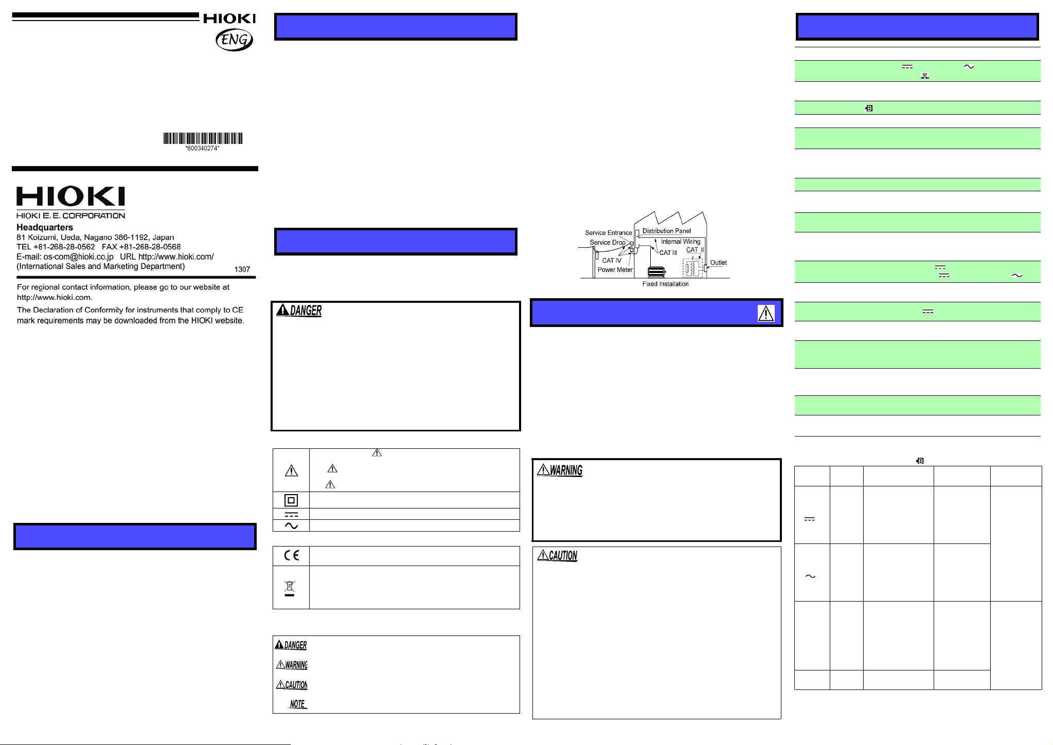
Measurement categories
This product complies with CAT III (300 V), CAT II (600 V) safety
requirements.
To ensure safe operation of measurement products, IEC 61010 estab-
lishes safety standards for various electrical environments, catego-
rized as CAT II to CAT IV, and called measurement categories.
CAT II: Primary electrical circuits in equipment connected to an AC
electrical outlet by a power cord (portable tools, household
appliances, etc.)
CAT II covers directly measuring electrical outlet receptacles.
CAT III:Primary electrical circuits of heavy equipment (fixed installa-
tions) connected directly to the distribution panel, and feeders
from the distribution panel to outlets.
CAT IV:The circuit from the service drop to the service entrance, and
to the power meter and primary overcurrent protection device
(distribution panel).
Using a measurement instrumentin an environment designated with a
higher-numbered category than that for which the instrument is rated
could result in a severe accident, and must be carefully avoided.
Use of a measurement instrument that is not CAT-rated in CAT II to
CAT IV measurement applications could result in a severe accident,
and must be carefully avoided.
Follow these precautions to ensure safe operation and toobtain
the full benefits of the various functions.
Preliminary Checks
• Before using the instrument the first time, verify that it oper-
ates normally to ensure that no damage occurred during stor-
age or shipping. If you find any damage, contact your dealer
or Hioki representative.
• To prevent an electric shock accident, confirm that the white
portion (insulation layer) inside the cable is not exposed. If a
color inside the cable is exposed, do not use the cable. Using
the instrument in such conditions could cause an electric
shock, so contact your dealer or Hioki representative for repair. Accuracy
Accuracy is guaranteed for 1 year at 23C±5C, 80%RH or less, and no
condensation. Battery low display is off.
*1: Input impedance *2: Frequency range *3: Open terminal voltage
*4: Threshold level (buzzer sound) *5: rdg. Displayed value, dgt. Resolution
Overview
3244-60
CARD HiTESTER
Instruction Manual
September 2013 Revised edition 4
Printed in Japan
3244L981-04 13-09H
(3244-61)
Inspection and Maintenance
Safety
This instrument is designed to comply with IEC
61010 Safety Standards, and has been thoroughly
tested for safety prior to shipment. However, mis-
handling during use could result in injury or death,
as well as damage to the instrument Using the
instrument in a way not described in this manual
may negate the provided safety features. Be certain
that you understand the instructions and precau-
tions in the manual before use. We disclaim any
responsibility for accidents or injuries not resulting
directly from instrument defects.
In the manual, the symbol indicates particularly important
information that the user should read before using the instrument.
The symbol printed on the instrument indicates that the user
should refer to a corresponding topic in the manual (marked with
the symbol) before using the relevant function.
Indicates a double-insulated device.
Indicates DC (Direct Current).
Indicates AC (Alternating Current).
This symbol indicates that the product conforms to safety regula-
tions set out by the EC Directive.
WEEE marking:
This symbol indicates that the electrical and electronic appliance
is put on the EU market after August 13, 2005, and producers of
the Member States are required to display it on the appliance
under Article 11.2 of Directive 2002/96/EC (WEEE).
Indicates that incorrect operation presents an extreme hazard that
could result in serious injury or death to the user.
Indicates that incorrect operation presents a significant hazard that
could result in serious injury or death to the user.
Indicates that incorrect operation presents a possibility of injury to
the user or damage to the device.
Indicates advisory items related to performance or correct opera-
tion of the product.
Usage Notes
• Do not allow the instrument to get wet, and do not take
measurements with wet hands. The instrument may
be damaged.
• Do not use the instrument where it may be exposed to
corrosive or combustible gases. The instrument may
be damaged or cause an explosion.
• Do not store or use the instrument where it could be exposed
to direct sunlight, high temperature or humidity, or conden-
sation. Under such conditions, the instrument may be dam-
aged and insulation may deteriorate so that it no longer
meets specifications.
• This instrument is not designed to be entirely water- or dust-
proof. Do not use it in an especially dusty environment, nor
where it might be splashed with liquid. This may cause damage.
• Correct measurement may be impossible in the presence of
strong magnetic fields, such as near transformers and high-
current conductors, or in the presence of strong electromag-
netic fields such as near radio transmitters.
• To avoid damage to the instrument, protect it from physical
shock when transporting and handling. Be especially careful
to avoid physical shock from dropping.
Specification
Measurement method
Double integration
Function DC voltage ( V), AC voltage( V), Resistance (),
Continuity check( )
Display 3-1/2 digits, LCD, 4199 count max. (except 500 V range)
3 digits, LCD, 549 count max. (500 V range)
Battery low display lights
Sampling rate 2.5 times/second
Dimensions and
mass Approx. 55W × 109H × 9.5D mm, Approx. 60 g
(Approx. 2.17"W × 4.29"H × 0.37"D, Approx. 2.1 oz).
Accessories Instruction Manual, carrying case,
Battery (supplied with this product for monitor),
Sleeves (red and black 1 piece for each)
Power supply Battery CR2032 (3 VDC) × 1
Dielectric strength 4.29 kVrms sin (50/60Hz for one minute) between input
and case
Maximum input
voltage 500 VDC/ 500 Vrms(sin) or 3×10⁶ V•Hz (DCV/ACV)
Maximum rated
voltage to earth
When sleeve is installed : CAT III (300 V)
When sleeve is uninstalled: CAT II (600 V)
(Anticipated Transient Overvoltage: 4000 V)
(50/60 Hz)
Noise rejection ratio NMRR:40 dB or more [ V]
CMRR:100 dB or more [ V], 60 dB or more [ V]
Maximum rated
power
15 mVA
Continuous
operating time Approx.150 hours [ V]
Operating
Environment Indoors, Pollution Degree 2, up to 2000 m (6562-ft.)
Operating
temperature and
humidity
0 to 40C (32 to 104 F), 80%RH max (no condensation)
Storage
temperature and
humidity range -20 to 60°C (-4 to 140 °F),
70%RH max (no condensation)
Temperature
characteristics Measurement accuracy x 0.1 /C (except 23C±5C)
Standards accuracy Safety :EN61010
EMC :EN 61326
Function Range Accuracy *5Remarks Over load
protection
DCV
[ V]
420.0 mV ±2.0% rdg. ±4 dgt. 100 M or over*1
500 V DC/
ACrms (sin)
or
3×10⁶V•Hz
4.200 V ±0.7% rdg. ±4 dgt. Approx. 11 M
42.00 V ±1.3% rdg. ±4 dgt. Approx. 10 M
420.0 V ±1.3% rdg. ±4 dgt. Approx. 10 M
500 V ±1.3% rdg. ±4 dgt. Approx. 10 M
ACV
[ V]
50 to 500 Hz *2
4.200 V ±2.3% rdg.±8 dgt. Approx. 11 M*1
42.00 V ±2.3% rdg.±8 dgt. Approx. 10 M
420.0 V ±2.3% rdg.±8 dgt. Approx. 10 M
500 V ±2.3% rdg.±8 dgt. Approx. 10 M
420.0 ±2.0% rdg. ±4 dgt. 3.4 V or less*3
500 V DC/
ACrms (sin)
(one minute)
4.200 k±2.0% rdg. ±4 dgt. 0.7 V (typ.)
42.00 k±2.0% rdg. ±4 dgt. 0.5 V (typ.)
420.0 k±2.0% rdg. ±4 dgt. 0.5 V (typ.)
4.200 M±5.0% rdg. ±4 dgt. 0.5 V (typ.)
42.00 M±10.0% rdg. ±4dgt. 0.5 V (typ.)
Continuity 420.0 ±2.0% rdg. ±4 dgt. 3.4 V or less*3
50 ±40 *4


