Timpte Tender User manual

Serving the transportation industry since 1884.
TIMPTE, INC.
1827 Industrial Drive
David City, NE 68632
402-367-3056
OPERATOR’S MANUAL
September 2019
TIMPTE
Bulk Commodity Trailer
with Combo Tender Option
011-51837
TenderCov19.indd 1 8/30/2019 10:10:25 AM

If you believe that this vehicle contains a safety defect you may contact Timpte Trailer
The trailer was designed and inspected to conform to industry standards and all applicable
NHTSA safety standards. Timpte Trailer Co. warrants this vehicle to be free from defects
in materials and workmanship when manufactured per the limited warranty agreement.
If you detect a defect that could cause an accident or could cause an injury or death; or if
you wish to report any such accident, injury or death, or any property damage claim or
other complaint not addressed to the Timpte Trailer Warranty Department, then you should
contact in writing:
Timpte Trailer Co.
Vice President of Engineering
1827 Industrial Drive
David City, NE 68632
Phone: 402-367-3056
Fax: 402-367-4340
If you believe that your vehicle has a defect which could cause a crash or could cause
injury or death, you should immediately inform the National Highway
Administration (NHTSA) in addition to notifying Timpte Trailer Co.
safety defect exists in a group of vehicles, it may order a recall and remedy campaign.
However, NHTSA cannot become involved in individual problems between you, your deal-
er, or Timpte Trailer Co.
To contact NHTSA, you may call the Vehicle Safety Hotline toll-free at 1-888-327-4236
(TTY: 1-800-424-9153); go to http://nhtsa.safercar.gov; or write to: Administrator, NHTSA,
1200 New Jersey Avenue SE, Washington, DC 20590. You can also obtain other information
about motor vehicle safety from http://www.safercar.gov
TenderCov19.indd 2 8/30/2019 10:10:25 AM

1Date of Origin – 02/24/11
Updated – 02/03/20
TABLE OF CONTENTS
NORMAL TRAILER OPERATION ..................................................................................................................................................................................................................3
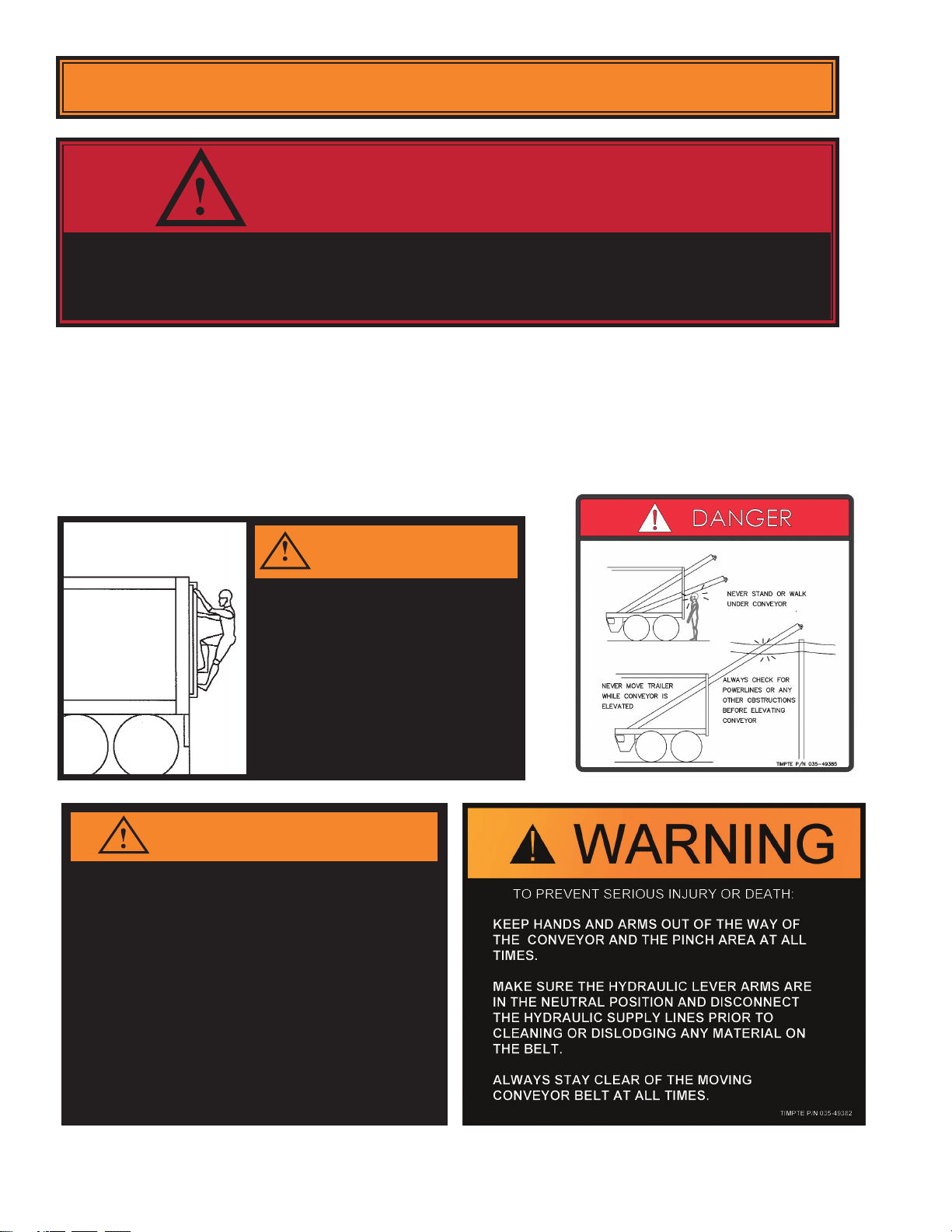
SAFETY ................................................................................................................................................................................................................................................4
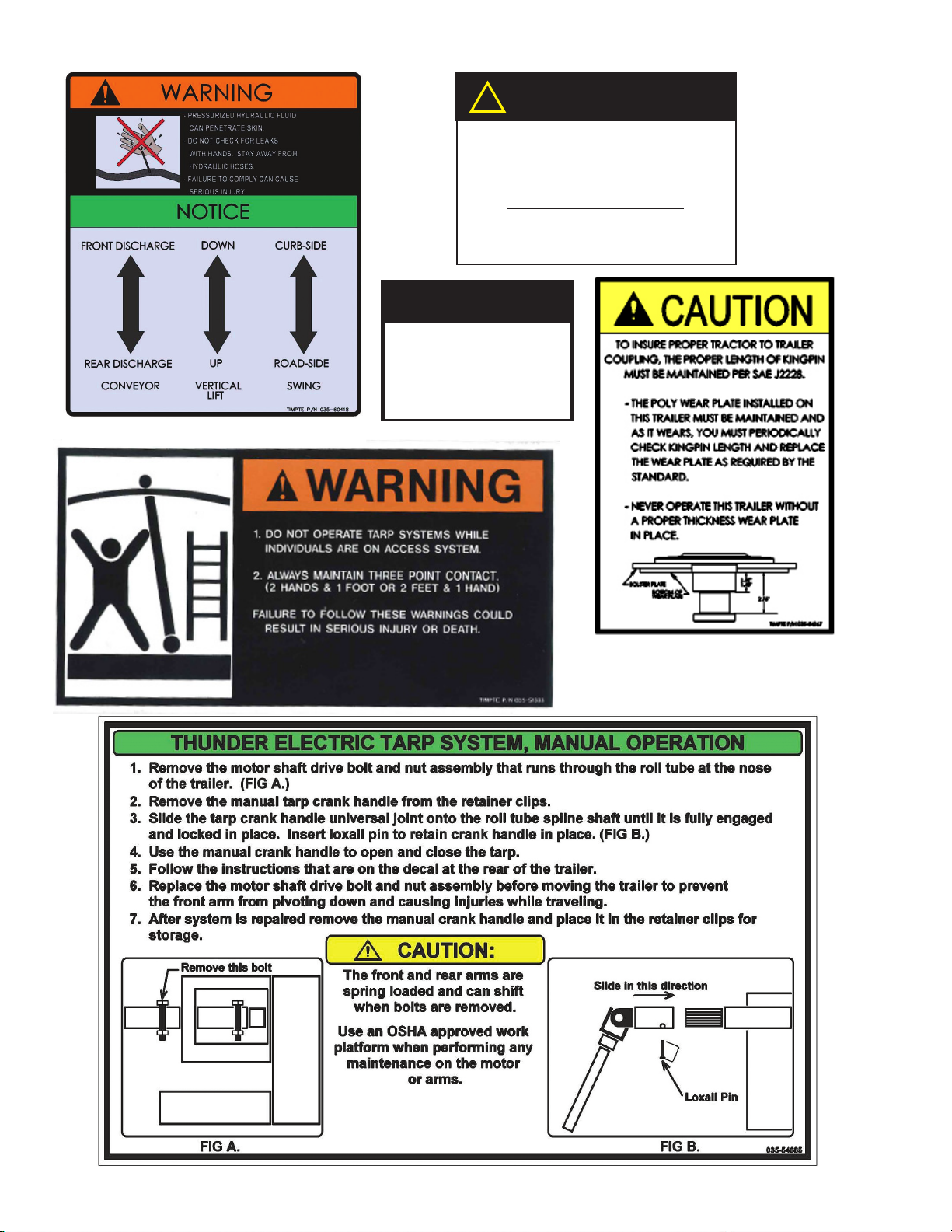
DECALS & WARNINGS.........................................................................................................................................................................................................4, 5, 6, 7
AIR BRAKE SYSTEM.........................................................................................................................................................................................................................8
WHEEL NUT TORQUE ......................................................................................................................................................................................................................8
ABS BRAKING SYSTEM ...................................................................................................................................................................................................................9
BACKUP WARNING SYSTEM...........................................................................................................................................................................................................9
CONTROL OF SAFE OPERATION .................................................................................................................................................................................................10
TRAILER KINGPIN WEAR............................................................................................................................................................................................................... 11
INSPECTION PROCEDURES BEFORE EACH TRIP .................................................................................................................................................................................12
LEGAL REQUIREMENT FMCS 49 CFR 392.7................................................................................................................................................................................12
LIGHTS AND REFLECTORS...........................................................................................................................................................................................................13
ELECTRICAL WIRING.....................................................................................................................................................................................................................13
FIFTH WHEEL AND KING PIN ENGAGEMENT..............................................................................................................................................................................13
TIRES ..............................................................................................................................................................................................................................................13
MUD FLAPS .................................................................................................................................................................................................................................... 13
TARP SYSTEM ................................................................................................................................................................................................................................ 13
LANDING GEAR .............................................................................................................................................................................................................................. 13
HUB MAINTENANCE...................................................................................................................................................................................................................... 13
WHEELS AND RIMS........................................................................................................................................................................................................................ 14
HUB LUBRICANT.............................................................................................................................................................................................................................14
SIDE STRUCTURES........................................................................................................................................................................................................................ 15
SUSPENSION AND SUSPENSION SUBFRAME ...........................................................................................................................................................................15
OPERATING INSTRUCTIONS.....................................................................................................................................................................................................................16
PARKING/EMERGENCY BRAKING SYSTEM.................................................................................................................................................................................16
OPERATING YOUR TIMPTE TENDER .......................................................................................................................................................................................................17
DUAL PURPOSE TENDER TRAILER OPERATING INSTRUCTIONS............................................................................................................................................ 17
TRAILER LOADING..............................................................................................................................................................................................................17
TRAILER UNLOADING.........................................................................................................................................................................................................18
SELF-CONTAINED POWER UNIT OPERATION............................................................................................................................................................................. 19
THUNDER ELECTRIC TARP SYSTEM ........................................................................................................................................................................................... 20
PROGRAMMING REMOTE TO WORK WITH THE THUNDER ELECTRIC TARP SYSTEM ..............................................................................................20
PROGRAMMING REMOTE TO WORK WITH THE EZ FLOW TRAP SYSTEM ..................................................................................................................21
THUNDER ELECTRIC TARP SYSTEM, MANUAL OPERATION .........................................................................................................................................22
TROUBLESHOOTING GUIDE..............................................................................................................................................................................................23
EZ-FLOW HYDRAULIC DOOR TROUBLESHOOTING GUIDE ......................................................................................................................................................25
PRESSURE RELIEF ADJUSTMENT ...............................................................................................................................................................................................26
EZ-FLOW QUICK RELEASE SYSTEM............................................................................................................................................................................................27
TRACTOR PTO SYSTEM “WET KIT” SPECIFICATIONS ...............................................................................................................................................................28
TENDER HYDRAULIC SYSTEM MAINTENANCE..........................................................................................................................................................................28
TIMPE TENDER TRAILER HYDRAULIC SCHEMATIC 577-60478.................................................................................................................................................29
SELF-CONTAINED TIMPTE TENDER TRAILER HYDRAULIC SCHEMATIC 577-60429............................................................................................................... 31
TENDER HYDRAULIC TESTING PROCEDURE ............................................................................................................................................................................ 33
CONVEYOR BELT TENSION AND TRACKING .............................................................................................................................................................................. 39
CONVEYOR BELT TRACKING ADJUSTMENT............................................................................................................................................................................... 40
GENERAL MAINTENANCE ......................................................................................................................................................................................................................... 41
AVOIDING CONTAMINATION.......................................................................................................................................................................................................... 41
TRAILER WASHING ........................................................................................................................................................................................................................ 41
CORROSIVE DETERIORATION...................................................................................................................................................................................................... 41
AIR HAMMER (VIBRATOR) MAINTENANCE..................................................................................................................................................................................42
HUB MAINTENANCE.......................................................................................................................................................................................................................44
WHEEL BEARING INSPECTION.....................................................................................................................................................................................................44
WHEEL BEARING ADJUSTMENT...................................................................................................................................................................................................44
BEARING LUBRICANT....................................................................................................................................................................................................................44
BRAKES...........................................................................................................................................................................................................................................46
AIR BRAKE SYSTEM - TROUBLESHOOTING ............................................................................................................................................................................... 47
BRAKE CONTROLS ........................................................................................................................................................................................................................48
AIR SYSTEM COLD WEATHER OPERATION ................................................................................................................................................................................48
AIR BRAKE PIPING SCHEMATIC .............................................................................................................................................................................................49, 50
CHECKING SPRING BRAKES ........................................................................................................................................................................................................51
AUTOMATIC SLACK ADJUSTERS..................................................................................................................................................................................................51
WHEEL ASSEMBLIES .....................................................................................................................................................................................................................52
WHEEL INSTALLATION...................................................................................................................................................................................................................52
TIRE CHANGE PROCEDURE.........................................................................................................................................................................................................53
AXLE ALIGNMENT...........................................................................................................................................................................................................................54
AIR-RIDE SUSPENSION SYSTEM ................................................................................................................................................................................................. 54
AIR-RIDE SUSPENSION SCHEMATIC ...........................................................................................................................................................................................55
ELECTRICAL SYSTEM DIAGRAM .....................................................................................................................................................................................57, 58, 59
LANDING LEGS...............................................................................................................................................................................................................................60
MAINTENANCE SCHEDULE - TENDER...............................................................................................................................................................................................61, 62
TIMPTE TENDER REFERNCE GUIDE .......................................................................................................................................................................................................63
REPORTING SAFETY DEFECTS - 49CFR 575.6 (a)(2)(ii).........................................................................................................................................................................64
TIMPTE “PEACE OF MIND” LIMITED WARRANTY....................................................................................................................................................................................65
TIMPTE BELT CONVEYOR SYSTEM WARRANTY COVERAGE & EXCLUSIONS ...................................................................................................................................66
FILING A WARRANTY CLAIM......................................................................................................................................................................................................................69

2
Date of Origin – 02/24/11 Updated – 02/03/20
This manual has been prepared to help you operate your new Timpte Tender trailer successfully, economically, and
safely. Please read your Operator’s Manual carefully and have a full understanding prior to using your trailer or
performing any maintenance. We urge you to contact your Timpte, Inc. factory representative or the Vice President
of Engineering at Timpte (402-367-3056) immediately should you have any questions or need an explanation.
Timpte has provided several warnings in your Operator’s Manual and on your trailer to help prevent personal injury.
Timpte can not foresee all use or misuse of the trailer. Always use common sense judgment while using or performing
maintenance to your trailer. Your safety is our primary concern.
This safety alert symbol is used throughout this manual to indicate potential personal safety hazards.
Failure to heed the warnings associated with the safety alert symbol can result in property damage, serious
injury or death.
Safety decals appear at various locations on your new tender trailer. The decals are provided for your safety and
should be kept clean. Replace any decal that has become worn or damaged, painted over, or otherwise difcult to
read. Replacement decals are available at no cost through Timpte by calling 402-367-3056.
Information contained in this Operator’s Manual is based on the latest information available at the time of publication.
Changes are continually being made to improve our product lines.
We want to thank you for purchasing a Timpte tender trailer and to let you know that it was built for long life and low
cost of operation. However, regular and proper maintenance of the trailer and your common sense use of it are
required to extend the life of the trailer.
IMPORTANT

3Date of Origin – 02/24/11
Updated – 02/03/20
This Timpte trailer is designed for operation within legal posted speed limits on reasonable road surfaces for the
type of service it was built to perform, in accordance with the noted weight restrictions.
“Normal Service” means the loading and transportation of uniformly distributed loads of properly secured, noncor-
rosive cargo, in accordance with any applicable factory instructions and in a manner which does not subject the
trailer or parts of the trailer to (a) concentrated loads; (b) loads in excess of the Gross Axle Weight Rating (GAWR)
or Gross Vehicle Weight Rating (GVWR) stated on the Certication Plate afxed to the trailer by Timpte; and (c)
accidental damage, or (d) stresses, impacts or shocks greater than those commensurate with normal, reasonable
lawful use.
The GAWR (gross axle weight rating) is the structural capability of the lowest rated member of the running gear
components: suspension system, hubs, brake drums, wheels, bearings, axles, brake linings or tires.
The GVWR (gross vehicle weight rating) is the structural capability of the trailer when supported by the kingpin and
axles with the load uniformly distributed throughout the cargo space.
NORMAL TRAILER OPERATION
The maximum load indicated on the identication plate
may not be a legal load on the highway you plan to use.
States have diering laws and regulations aecting
vehicle lengths and weights on roads that are not a part
of the primary interstate road system.
Modication of the Trailer – Any modication made to the trailer must comply with DOT and NHTSA reg-
ulations and must not compromise the gross vehicle weight rating (GVWR) of the trailer. Any modication made to
the trailer without prior approval of Timpte may void the warranty. Any operation of the trailer outside the limitations
stated in this manual will void any responsibility of Timpte, Inc. for any of its results.
NOTICE:

4
Date of Origin – 02/24/11 Updated – 02/03/20
WARNING
PERSONAL INJURY, DEATH, AND PROPERTY DAMAGE MAY RESULT FROM
IMPROPER OPERATION OR UNSAFE PRACTICES. BE SURE TO READ AND
FOLLOW ALL DECALS AND EMBLEMS CAREFULLY.
The following section contains safety warnings and operational directions. Some of these
are used as decals on the Timpte Tender Trailers. Due to dierences in congurations and
equipment, your trailer may or may not use all the decals and emblems shown. Newer
trailers may also have decals and emblems that dier from older trailers. Replace damaged
or missing decals promptly. Replacement decals for this trailer are available without charge
by calling Timpte, Inc. at 402-367-3056.
SAFETY
CAUTION
WARNING
1. EXERCISE EXTREME CAUTION WHILE CLIMBING
ON ACCESS SYSTEM.
2. ALWAYS MAINTAIN 3-POINT CONTACT.
(2 HANDS & 1 FOOT OR 2 FEET AND 1 HAND)
3. DO NOT WEAR RINGS OR ANYTHING THAT
CAN CATCH ON LADDER.
4. USE LADDER SIDE RAIL FOR HAND HOLD, NEVER
USE THE RUNG.
5. NEVER CLIMB OVER THE TOP OF THE TRAILER.
NEVER ENTER THE INSIDE COMPARTMENTS
FOR ANY REASON.
FAILURE TO FOLLOW THESE WARNINGS COULD RESULT
IN SERIOUS INJURY OR DEATH.
WARNING
THIS TRAILER IS EQUIPPED WITH ANTILOCK BRAKE SYSTEM (ABS).
D.O.T. REGULATION FMVSS-121 REQUIRE ABS RECEIVE CONSTANT
POWER FROM THE CENTER AUXILIARY PIN ON THE 7-WAY CONNECTOR.
INSPECT YOUR TRACTOR! TRACTOR MUST SUPPLY CONTANT POWER
FOR THE ABS ON THE CENTER AUXILIARY PIN WHEN THE KEY SWITCH
IS ON. DEACTIVATE ANY SWITCH IN THE TRACTOR THAT WILL TURN THE
AUXILIARY POWER OFF (MUST SUPPLY CONSTANT POWER).
DO NOT MODIFY THE TRAILER ELECTRICAL SYSTEM TO POWER OPTION-
AL EQUIPMENT OFF THE AUXILIARY CIRCUIT. FEDERAL LAW MANDATES
THIS CIRCUIT IS DEDICATED FOR ABS ONLY.
CONTACT TIMPTE ENGINEERING IF YOU HAVE ANY QUESTIONS ABOUT
YOUR PRESENT WIRING OR HOW TO REWIRE FOR AUXILIARY EQUIP-
MENT.
FAILURE TO FOLLOW THESE WARNINGS COULD RESULT IN SERIOUS
INJURY OR DEATH.

5Date of Origin – 02/24/11
Updated – 02/03/20
WARNING
!
THIS TRAILER IS EQUIPPED WITH TRAILING BEAM AIR
RIDE SUSPENSION.
1. MANUALLY EXHAUST ALL AIR IN THE SUSPENSION
SYSTEM PRIOR TO SUPPORTING A LOADED TRAILER
ON THE SUPPORT LEGS. FAILURE TO COMPLY CAN
CAUSE STRUCTURAL DAMAGE TO THE SUPPORT LEG
BRACES.
2. DO NOT USE EXCESSIVE FORCE WHEN COUPLING THE
TRACTOR TO THE TRAILER (EMPTY OR LOADED) CON-
TINUING TO BACK-UP A TRACTOR/TRAILER WITH THE
TRAILER BRAKES LOCKED CAN ROTATE THE TRAILING
BEAMS AND OVEREXTEND THE SUSPENSION. OVEREX-
TENSION WILL CAUSE DAMAGE TO THE SUSPENSION
SYSTEM.
3. MANUALLY EXHAUST ALL AIR IN THE SUSPENSION
SYSTEM PRIOR TO AND DURING UNLOADING THE
TRAILER. AFTER UNLOADING THE TRAILER, IMMEDI-
ATELY ACTUATE THE AIR AND WAIT FOR THE SUSPEN-
SION TO RETURN TO THE NORMAL RIDE HEIGHT BEFORE
MOVING THE VEHICLE.
WARNING
!
– DO NOT ATTEMPT TO WALK ON
TOP RAILS, THEY ARE NOT AN
APPROVED WALKWAY
– FAILURE TO COMPLY CAN CAUSE
SERIOUS INJURY OR DEATH
WARNING
!
NEVER CLIMB INSIDE THE HOPPER COMPARTMENT!
FAILURE TO FOLLOW THIS WARNING COULD RESULT IN
SERIOUS INJURY OR DEATH.
WARNING
USE KNOCK RAILS TO DISLODGE COMMODITY,
POUNDING ON SLOPE SHEETS VOIDS WARRANTY.
P/N 035-03082

6
Date of Origin – 02/24/11 Updated – 02/03/20
NEW FMVSS-121 REGULATIONS MANDATE HIGHER PRES-
SURE LEVELS IN THE SUPPLY LINE.
TRAILER BRAKE PERFORMANCE WILL BE
IMPAIRED IF TRACTOR COMPRESSOR
ADJUSTMENT IS TOO LOW.
CHECK YOUR TRACTOR!
COMPRESSOR CUT-IN PRESSURE, ADJUST TO 105 PSI CUT-IN
GOVERNOR
CAUTION
P/N 035-29182
!
DO NOT ATTEMPT
TO HOIST TRAILER
AT THIS FRAME
STRUCTURE.
P/N 035-27163
CAUTION

7Date of Origin – 02/24/11
Updated – 02/03/20

8
Date of Origin – 02/24/11 Updated – 02/03/20
AIR BRAKE SYSTEM
Your new Timpte trailer is equipped with an air brake system which meets or exceeds the requirements of the federal
regulation FMVSS-121 for grade-holding ability and emergency stopping in the event of an air supply failure in the
service brake system. Air pressure is required to release the parking/emergency brake. As of 10/8/92-FMVSS 121
requires that the supply line for the air brake system be protected to 70 psi. This pressure level requires that supply
line pressure levels are achieved before the pressure protection valve opens (opening pressure must be higher than
the closing pressure by design).
Keeping your compressor cut-in pressure at maximum levels (over 100 psi) is a clear advantage for peak operation of
your entire system, we recommend using a 105 psi cut-in governor setting. Governor cut-out pressure should be at
120 psi minimum. Low compressor cut-in pressure may result in poor performance of the system, for example slow
parking brake release time.
Should you still have a problem with your brake system after working through all of the inspection items and tests listed
in this manual’s maintenance section, contact your Timpte factory representative.
WHEEL NUT TORQUE
Proper torquing and retorquing the wheel nuts are critical to prevent the loss of wheel equipment. Wheel nuts should
be torqued to 450 to 500 ft. lbs. (dry). Refer to the manufacturer’s decal on the side of the trailer or manufacturer’s
maintenance information supplied with the trailer for proper torque specications and tightening sequence.
Wheels must be checked and retorqued after the rst 50 to 100 miles of use. This is important every time you change
a wheel. Check the fastener torque on a regular on-going basis.
REAR IMPACT GUARDS
WARNING
1. Read and understand this warning and the installation, Service and Safety Instruction Manual to understand
all safety precautions, proper operation, and maintenance of your Webb hub. Failure to do so could result in
death or serious injury and could result in a compromise of your vehicle’s safe operation through loss or failure
of a wheel or the compromise of the braking system. Copies of the installation, Service and Safety Instruction
Manual are available, free of charge, from Webb Products, Inc., upon request.
2. Always use a properly installed calibrated torque wrench to assure proper torque. Under torque and over
torque can cause thread and/or nut damage and could result in the loss of a wheel. Failure to ensure proper
torque could result in death or serious injury and could shorten the expected life of this product.
3. Recheck torque after the first 50 to 100 miles of service. Parts may seat naturally, causing the torque to drop.
A drop in torque could result in the loss of a wheel. Proper torque is essential to avoid damage or compromise
of your vehicles safety. Failure to ensure proper torque could result in death or serious injury.
2310 INDUSTRIAL DRIVE, S.W.
CULLMAN, ALABAMA 35055
256-739-6660 WWW.WEBBWHEEL.COM
HUBS
(FOR PILOT MOUNTED DISC WHEELS)
8 - 10 STUD HUBS
APPLIES TO M22 X 1.5 STUDS / TWO PIECE FLANGE NUT.
All threads are right hand metric.
Tighten Flange Nuts to 50 ft.lb. using sequence
shown.
Check Disc-Wheels for proper positioning on pads
and proper seating against flange.
Tighten Flange Nuts to recommended torque using
sequence shown.

9Date of Origin – 02/24/11
Updated – 02/03/20
ABS BRAKING SYSTEM
As of 3/1/98 all trailers manufactured with air braking systems are required to have an ABS (Anti-Lock Braking
System).
The system used on your trailer meets or exceeds the FMVSS 121 requirement for ABS. The ABS system on
your Bulk Commodity trailer is a 4S/2M system (4 wheel sensors - 2 modulator valves) or a 2S/1M (2 wheel sensors
- 1 modulator valve). The intended purpose of ABS is to help maintain control and reduce the likelihood of jackknife
situations.
The ABS status indicator light is located on the driver side of the trailer near the rear corner post. It indicates the
system status upon initial startup by turning on and then turning off once the vehicle begins to move. If a malfunction
in the ABS system occurs, the ABS system status light will come on and stay on until the problem is repaired. Anytime
the system status light comes on and stays on, have the ABS system serviced as soon as possible.
WARNING! ABS (Anti-Lock Braking System) is a safety item and must be
properly maintained. To operate an ABS equipped truck and trailer properly, during
braking- constant pedal force must be applied. All ABS systems require clean, dry
air to operate properly. Use of airline deicers or leakage of oil into the air system
may diminish the performance of the system and will void the warranty.
BACKUP WARNING SYSTEM
A backup warning system consisting of an audible alarm is available as an option on your Timpte Bulk Commodity
trailer. The system is intended to indicate that the vehicle is backing up.

10
Date of Origin – 02/24/11 Updated – 02/03/20
1. You, the operator, have control of the most important factors that affect safe trailer operation and vehicle
stability. Trailers are a tool and, like any tool, are safe only when properly used by a conscientious, trained
and qualied operator.
2. The fth wheel should be securely mounted to the tractor frame and proper connection
between the tractor and trailer veried.
3. The driver should be familiar with the characteristics of the particular trailer and of the load to be
transported.
4. The driver should be familiar with the nature of the roads and trafc which may be encountered during
the trip.
5. Stability – Caution - like any other vehicle, semi-trailers can tip or slide out of
control if turns are negotiated at too high a speed or when making violent
maneuvers such as abrupt lane changes or other evasive actions to avoid
obstacles.
6. Within the relatively narrow connes of road laws limiting vehicle size and weight, together with the
characteristics of available tires, suspensions, and other components, there is little that a manufacturer can
do to affect the inherent stability of a trailer other than keeping the load as low as feasible, considering the
requirements for loading space and adequate tire clearance. This means that the major factors affecting
operational stability are the knowledge and skill of the driver. The predominant causes of rollover
accidents are:
a. Excessive speed
b. Violent swerving or turning
c. Application of brakes or tractor power while turning.
d. Entering curves at too high a speed
7. Tire Characteristics: High pressure truck/trailer tires have different characteristics under high speed corner-
ing conditions than do passenger car tires. Truck/trailer tires are designed for carrying high loads over long
distances. Their lateral stability becomes unpredictable when lateral forces approach .04g. This means
that commercial vehicles must be operated in a conservative manner when cornering.
8. Braking and Acceleration: Either braking or accelerating while cornering can signicantly reduce the stability
of the vehicle and should be avoided. The best driving practice is to decelerate to a safe conservative
speed before entering a corner or approaching congested trafc, and then to apply only moderate power
until a straight path has been re-established.
You, the operator, have the Greatest Control
over Safe Operation.

11 Date of Origin – 02/24/11
Updated – 02/03/20
TRAILER KINGPIN WEAR
Per Recommended SAE Standards, check King Pin for
wear across the pin neck and also the pin shoulder. In
accordance with industry standards, Timpte recommends
that the kingpin and its mounting structure be inspected
for wear and damage on a daily basis.
1. Measure the neck - 2”
A. Insert the head of the Kingpin through the
large opening of the small slot. Locate the
gage between the shoulder and the head of
the Kingpin.
B. Slide the gage toward the small end. The number stamped on the gage at the center
of the Kingpin indicates the dimension (see gure 1).
C. The Kingpin should be replaced when, at any orientation, the neck OD measures
1 7/8” diameter.
2. Measure the shoulder - 2-7/8”
A. Repeat the above procedure using the large slot on the shoulder of the Kingpin (see gure 2).
B. The Kingpin should be replaced when, at any orientation, the shoulder OD measures 2 ¾” diameter.
TRAILER KINGPIN TO COUPLER INTERFACE INSPECTION CRITERIA
3. Measure the Kingpin length
The Kingpin is the proper length if the “MAX” end engages and the “MIN” end does not engage as shown below.
Important: Be sure to hold the gage edge at to the upper coupler. Check both the “MAX” end and the “MIN”
end as shown in gures 3 and 4.
Reference SAE J2228 standard for kingpin wear
Reference SAE J700 standard for upper coupler to kingpin interface
WARNING
TO INSURE PROPER ENGAGEMENT OF THE
KING PIN TO THE FIFTH WHEEL COUPLER,
THE KINGPIN MUST BE MAINTAINED WITHIN
RECOMMENDED SAE STANDARDS. FAILURE TO
DO SO COULD CAUSE SERIOUS INJURY OR
DEATH.

12
Date of Origin – 02/24/11 Updated – 02/03/20
WARNING! Be careful when making inspections, hookups and repairs to
avoid personal injury. Make sure parking brakes are properly activated or that
wheel chocks are in place to avoid sudden or unexpected movement of the
trailer which could result in bodily injury.
It is the Operator’s responsibility to conduct a safe and accurate pre-
trip inspection of the vehicle. Per Federal Motor Carrier Statute 49 CFR
392.7 Equipment, Inspection and Use - No motor vehicle shall be driven
unless the driver thereof shall have satised himself that the following
parts and accessories are in good working order, nor shall any driver fail
to use or make use of such parts and accessories when and as needed
Service Brake, including trailer brake connections
Parking Brake
Steering Mechanism
Lighting devices and reectors
Tires/Tire Pressure
Horn
Windshield Wiper or wipers
Rear-vision mirror or mirrors
Coupling devices
Hoses and Airlines
Fifth Wheel Plate
Gladhand Connections
Hub Maintenance
Mud Flaps
RIG (Rear Underride Guard)
NOTICE:
Additional Federal Requirements for the Operator can be found in the Federal Motor Carrier Safety Regulations
(FMCSR’s) in the Code of Federal Regulations (CFR) Title 49 Parts 392, 393 and 396. These can be found on-line at
http://www.access.gpo.gov/nara/ then scroll down to (CFR Sections by Citation).
Failure to regularly inspect the trailer may also void the warranty.
While it is ultimately the operator’s responsibility to properly perform and document the pre-trip inspection, Timpte
provides the following recommendations and suggestions.
Inspection Procedures Before Each Trip

13 Date of Origin – 02/24/11
Updated – 02/03/20
LIGHTS AND REFLECTORS
The surfaces of the lights and reectors need to be checked and cleaned. Inspect all lights to see if they are working
and check all brake and signal functions.
ELECTRICAL WIRING
Inspect all visible wiring to see that it is not frayed and is properly supported and protected, and that all connections
are tight. Inspect the electrical hookup for a clean and secure connection.
FIFTH WHEEL AND KING PIN ENGAGEMENT
Inspect the kingpin and its structure on the trailer for damage or unusual wear. After hook up, make a direct visual in-
spection to assure proper coupling, then check for positive engagement of the lower fth wheel and king pin. Apply the
trailer brakes and attempt to move the tractor forward to insure that the fth wheel and king pin are positively locked.
CAUTION! Plastic King Pin Liners (Lube Plate) cannot be installed onto Timpte Trailer upper cou-
pler/king pin assemblies unless the trailer was purchased with that specication. A lube plate changes
the king pin interface dimensions relative to the fth wheel lock. This may result in coupling difculties,
premature lock wear, and a potential for a dropped trailer.
TIRES
WARNING! DO NOT OVERLOAD! Check tires frequently for cuts and abrasions. Check tire
pressure daily and keep inated as recommended by the tire manufacturer. Remove foreign objects that
may be lodged in the tire treads or between dual tires.
MUD FLAPS
Be sure the mud aps are securely in place and in good condition.
TARP SYSTEM
Check to be sure the tarp is in serviceable condition. Insure that the latching system is in good working order and that
the tarp is properly secured for travel to prevent being blown about by the wind.
LANDING GEAR
Always raise the landing gear legs completely before moving the trailer. Make sure that the crank handle is properly
secured. Prior to trailer transport, lock landing legs into low side gear ratio.
HUB MAINTENANCE
Check wheel studs for good condition – no stripped threads – no bent or loose studs. Replace any broken or bent
studs or studs with damaged threads. When a broken stud is replaced, the stud on each side of it should be replaced
at the same time. If more than two studs on the same hub are broken, replace all of the studs.

14
Date of Origin – 02/24/11 Updated – 02/03/20
WHEELS AND RIMS
Check all wheel nuts for tightness. Wheel ange nuts should be torqued to 450 to 500 ft. lbs (dry).
Check all metal surfaces thoroughly while making tire inspections and during tire changes.
Look for:
• Excessive rust or corrosion build-up
• Cracks in the metal
• Bent anges or components
• Loose, missing, or damaged nuts
• Bent or stripped studs.
• Incorrectly matched rim parts
Replace damaged components, making sure that replacements are made with proper sized and type parts.
WARNING
EXCESSIVELY CORRODED OR CRACKED RIMS ARE DANGEROUS, PARTICU-
LARLY DURING REMOVAL. DEFLATE TIRES PRIOR TO REMOVAL OF RIMS AND
WHEELS FROM THE VEHICLE OR PERSONAL INJURY COULD RESULT.
HUB LUBRICANT
Check and maintain proper level of lubricant in hubs.
Hubs using oil lubricant will have clear hub windows and the oil level will be clearly visible. Be sure the oil level is at
the ll line noted on the hub window.
Hubs equipped with synthetic grease will retain the grease between the bearings and no lubricant visual check is pos-
sible. Trailers equipped with this option will not have a clear hub window or a ll plug.
Do not add oil to hubs equipped with synthetic grease lubricant. If mixing of lubricants occurs, remove the lubricant
and re-install the proper lubricant as soon as possible.
NOTE: Hub cap mounting bolts (6) torque 10 to 15 ft. -lbs torque per bolt.

15 Date of Origin – 02/24/11
Updated – 02/03/20
SIDE STRUCTURES
Check the trailer sides for inconspicuous damage to the top and bottom rails as well as the side structure – cracks,
contusions, sharp bends, ripples, or missing fasteners. Any problems observed in the side structure should be correct-
ed immediately to prevent the damage from extending further. Unrepaired damage could affect the safe load carrying
capacity of the side structure.
SUSPENSION AND SUSPENSION SUBFRAME
Check the suspension and suspension subframe structure for damage or unusual wear. Any type of damage, cracks
in the welds or structural members or loose fasteners need to be addressed immediately. Check air ride suspensions
for condition of bushings, air leaks, condition of shock absorbers, for proper operation of ride height leveling valve, and
for proper ination of the air springs.
NOTE: Never move an air ride trailer without rst fully inating the air springs – failure to
do so could cause damage to the trailer and suspension and will void the warranty.

16
Date of Origin – 02/24/11 Updated – 02/03/20
PARKING/EMERGENCY BRAKING SYSTEM
This portion of the air brake system makes provision for parking a vehicle on a grade and for emergency stopping in
the event of a failure of air supply in the service brake system.
Air pressure within the parking brake chamber is required to release the spring brake. An air reservoir is provided to
store enough air to release the brakes at least once by means of the tractor parking brake control, if there is an air line
failure. In addition to the normal release of spring brakes using air, a built-in manual release is provided. It allows easy
release of the spring brakes for relining the brakes or for moving the trailer in the absence of air pressure.
WARNING
DO NOT ATTEMPT TO MOVE THE TRAILER UNTIL PARKING BRAKE IS FULLY RE-
LEASED. FAILURE TO FOLLOW THIS SAFETY WARNING WILL RESULT
IN EQUIPMENT DAMAGE AND COULD RESULT IN SERIOUS INJURY
OR DEATH.
DANGER
MANUAL RELEASE OF THE PARKING BRAKE SHOULD ONLY BE USED TO MOVE
THE TRAILER TO A SAFE LOCATION WHERE REPAIRS CAN BE PERFORMED.
ALWAYS INSTALL WHEEL CHOCKS IN FRONT OF AND BEHIND TIRES BEFORE
MANUALLY RELEASING SPRING BRAKES. FAILURE TO FOLLOW THIS SAFETY
WARNING COULD RESULT IN DEATH OR SERIOUS INJURY.
WARNING
NEVER ATTEMPT TO USE THE TRAILER FOR THE MAJORITY OF THE BRAKING
EFFORT BY BACKING OFF THE TRACTOR BRAKES. THIS IS ILLEGAL, UNSAFE,
AND WILL CAUSE PREMATURE FAILURE OF THE TRAILER BRAKE SYSTEM.
FAILURE TO FOLLOW THIS SAFETY WARNING COULD RESULT IN
DEATH OR SERIOUS INJURY.
OPERATING INSTRUCTIONS

17 Date of Origin – 02/24/11
Updated – 02/03/20
OPERATING YOUR TIMPTE TENDER
Inclined Conveyor
Horizontal Conveyor
TRAILER LOADING
• Roll tarp to open position and lock crank handle in place.
• Check trap doors for closure, locks and latches for proper engagement before loading.
• Position trailer to receive commodity.
• Set parking brake on the tractor prior to loading the commodity into the trailer.
• The trailer should be loaded evenly from front to rear, maintaining all state bridge laws.
DO NOT Overload the trailer as this action could void the trailer warranty.
• Use the air system air guage to determine legal load conditions. Calibrate the air
gauge by comparing gauge pressure to loaded trailer scale weight.
• The tarp bows can be swung to the side to facilitate loading as needed. Be sure to use a safe,
approved walkway or scaffold to reach and manipulate bows.
• Balance the load between front and rear hoppers.
• Roll the tarp closed and lock the crank handle into place before proceeding to another location.
WARNING
AT NO TIME SHALL YOU TRY TO DISLODGE COMMODITY IN THE CONVEYOR
WHILE THE SYSTEM IS OPERATING! DO NOT CHECK FOR OIL LEAKS WITH YOUR
HANDS. NEVER WALK UNDER THE INCLINED CONVEYOR!! KEEP AWAY FROM
OVERHEAD POWER LINES OR OTHER OBSTRUCTIONS WITH THE INCLINED CON-
VEYOR. KEEP ALL PERSONNEL CLEAR OF CONVEYOR SYSTEM DURING
OPERATION, RAISING AND LOWERING OF THE CONVEYOR ETC.

18
Date of Origin – 02/24/11 Updated – 02/03/20
• Before positioning trailer to off load the commodity, conrm
overhead clearance is adequate to prevent the auger from
hitting power lines, trees, buildings, etc.
o Trailer must be positioned to sit level.
• Open the tarp on your Timpte trailer for ventilation.
• Verify that the hydraulic control levers are in the neutral position.
• Engage tractor wet kit, or self-contained power unit.
o Do not exceed 30 PGM ow.
• Adjust the incline conveyor to the desired height by moving
the vertical lift cylinder lever.
o Pull out to raise the incline conveyor, and push in to lower.
o See decal on side of trailer.
• Adjust the incline conveyor to the desired swing position,
side to side by moving the swing cylinder lever.
o Pull out to move the discharge to the
road side or toward you, and push to move
the discharge to the curb side or away
from you.
o See the decal on side of trailer.
• Adjust the incline conveyor to the desired position moving the
appropriate lever. See decal on the side of the trailer.
• Push the lever in to discharge the commodity thru the rear incline
conveyor.
• Pull the lever out to discharge the commodity out the bottom of the trailer
at the front of the horizontal conveyor.
• Open the trap door for the compartment that you want dis charged
(see section “EZ-Flow Door Operation”).
• When the trailer is unloaded, close the trap doors and stop the
conveyors by returning the appropriate lever to the center or neutral
position.
• Position the inclined conveyor to the lowest centered position
before transporting.
• Disengage the tractor wet kit or self-contained power unit to stop the
pumping of hydraulic uid.
TRAILER UNLOADING
Note: Timpte Trailers are designed to transport free owing commodity. Knock rails and pneumatic (air) hammer (vibra-
tor) options are available to be installed to assist with the unloading of commodity, if needed. Speak with a Timpte Sales
Representative with any questions you may have with respect to knock rails and pneumatic (air) hammer options.
Conveyors On/O
Incline Raise/Lower
Incline Swing Side to Side
Table of contents
Other Timpte Utility Vehicle manuals