Sioux Automation Center TURBO-MAX 6141 Programming manual

QUALITY PEOPLE, QUALITY PRODUCTS
Sioux Automation Center, Inc.• 877 1st Ave NW • Sioux Center, IA 51250
PH: (712-722-1488) • Toll Free: 1-866-722-1488
www.siouxautomation.com
ASSEMBLY
CALIBRATION
OPERATION
REPLACEMENT PARTS
READ COMPLETE MANUAL CAREFULLY
BEFORE ATTEMPTING OPERATION
4/22/2010
MON600194
REV B
OPERATORS/PARTS MANUAL
TURBO-MAX
6141 TRAILER

Page 2
Never overload wagon. Follow rating of gear or rating of tires, whichever is less.
Ensure that anybody present is clear before applying power to any machinery used in conjunc-
tion with wagon box or when moving box.
Never allow anyone in, near, or on mixing chamber during mixing, transporting, or unloading
of feed.
Do not exceed 20 miles per hour when towing wagon.
GENERAL INFORMATION
1. Unless otherwise specified, high-strength (grade5) (3
radial-line head markings) hex head bolts are used
throughout assembly of this piece of equipment.
2. Whenever terms “LEFT” and “RIGHT” are used in this
manual it means from a position behind the wagon box
and facing forward.
3. When placing a parts order, refer to this manual for
proper part numbers and place order by PART NO. and
DESCRIPTION.
4. Read assembly instructions carefully. Study
assembly procedures and all illustrations before you begin
assembly. Note which parts are used in each step. This
unit must be assembled in proper sequence or complica-
tions will result.
WARNING: TO AVOID PERSONAL INJURY OR DEATH, OBSERVE FOLLOWING
INSTRUCTIONS:
Thank you for purchasing a Sioux Automation Turbo-Max 6100 series reel mixer. We feel you have
made a wise choice and hope you are completely satisfied with your new piece of equipment. Your new 6100
series Turbo-Max is a durable, efficient, and easy to use unit. Proper care and use will result in many years of service.
INTRODUCTION
Table of Contents
General Information ................................................................................................................................................ 2
Model and Serial Number Identification...................................................................................................................3
Safety, Signal Words............................................................................................................................................... 4
Equipment Safety Guidelines.................................................................................................................................. 5
Lighting and Marking............................................................................................................................................... 5
Safety Sign Care..................................................................................................................................................... 5
Tire Safety............................................................................................................................................................... 6
Before Operation. . . . . . . . . . . . . . . . . . . . . . . . . . . . . . . . . . . . . . . . . . . . . . . . . . . . . . . . . . . . . . . . . . . . . . . . . . . . . . . . . . . . . . . . . . . . . . . . . . . . . . . . . . . . . . . . . . . . . . . . . . . . . . ....................... 6
During Operation. . . . . . . . . . . . . . . . . . . . . . . . . . . . . . . . . . . . . . . . . . . . . . . . . . . . . . . . . . . . . . . . . . . . . . . . . . . . . . . . . . . . . . . . . . . . . . . . . . . . . . . . . . . . . . . . . . . . . . . . . . . . . . ......................7-8
Following Operation ................................................................................................................................................ 8
Highway and Transport Operations .......................................................................................................................8-9
Performing Maintenance........................................................................................................................................ 10
Bolt Torque ............................................................................................................................................................. 11
PTO Horsepower Requirements ............................................................................................................................ 12
Drawbar Attaching System. . . . . . . . . . . . . . . . . . . . . . . . . . . . . . . . . . . . . . . . . . . . . . . . . . . . . . . . . . . . . . . . . . . . . . . . . . . . . . . . . . . . . . . . . . . . . . . . . . . . . . . . . . . . . . . . . . . . . . . . . . . . . . ....... 12
Hydraulic System ................................................................................................................................................... 12
Mixer Setup. . . . . . . . . . . . . . . . . . . . . . . . . . . . . . . . . . . . . . . . . . . . . . . . . . . . . . . . . . . . . . . . . . . . . . . . . . . . . . . . . . . . . . . . . . . . . . . . . . . . . . . . . . . . . . . . . . . . . . . . . . . . . . .............................. 12
Mixer Operation ...................................................................................................................................................13-15
Inspection and Adjustment...................................................................................................................................15-16
Electronic Scales ................................................................................................................................................... 16
Lubrication ............................................................................................................................................................. 17
Decal Location ....................................................................................................................................................... 18
Model Specifications .............................................................................................................................................. 19
BoxBase Assembly ..............................................................................................................................................20-23
Reel Assembly .................................................................................................................................................... 24
Wiper Tube Assembly .......................................................................................................................................... 25
Bearing Assembly ................................................................................................................................................ 26
Auger Assemblies ................................................................................................................................................ 27
Trailer Base Assembly .........................................................................................................................................28-29
Subframe Assembly ............................................................................................................................................... 30
Hub & Spindle Assemblies .................................................................................................................................... 31
Final Assembly. . . . . . . . . . . . . . . . . . . . . . . . . . . . . . . . . . . . . . . . . . . . . . . . . . . . . . . . . . . . . . . . . . . . . . . . . . . . . . . . . . . . . . . . . . . . . . . . . . . . . . . . . . . . . . . . . . . . . . . . . . . . . . ......................... 32
Slide Tray Breakdown ............................................................................................................................................ 33
Power Discharge Breakdown ..............................................................................................................................34-35
Hydraulics Breakdown .........................................................................................................................................36-40
Control Box Breakdown ........................................................................................................................................ 41
1000 PTO Conversion Kit ...................................................................................................................................... 42
Driveline Assembly . . . . . . . . . . . . . . . . . . . . . . . . . . . . . . . . . . . . . . . . . . . . . . . . . . . . . . . . . . . . . . . . . . . . . . . . . . . . . . . . . . . . . . . . . . . . . . . . . . . . . . . . . . . . . . . . . . . . . . . . . . . . . . ................43-44
Lighting Breakdown ............................................................................................................................................... 45
Warranty...............................................................................................................................................................46-47
Page 3
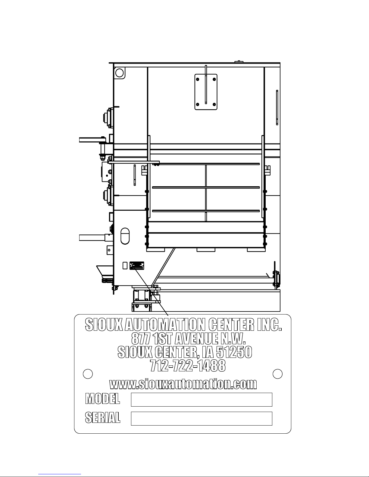
MODEL AND SERIAL NUMBER IDENTIFICATION
Your model and serial numbers can be located on the front left hand side of the mixer. Please copy this information and write
them down inside of this manual. This will allow easy reference if the ordering of parts should become necessary.

Page 4
SAFETY, SIGNAL WORDS
SAFETY
TAKE NOTE! THIS SAFETY ALERT SYMBOL FOUND THROUGHOUT THIS
MANUAL IS USED TO CALL YOUR ATTENTION TO INSTRUCTIONS INVOLVING YOUR
PERSONAL SAFETY AND THE SAFETY OF OTHERS. FAILURE TO FOLLOW THESE
INSTRUCTIONS CAN RESULT IN INJURY OR DEATH!
THIS SYMBOL MEANS
ATTENTION!
BECOME ALERT!
YOUR SAFETY IS INVOLVED!
SIGNAL WORDS
Note the use of the signal words DANGER, WARNING
and CAUTION with the safety messages. The appropriate
signal word for each has been selected using the following
guidelines:
DANGER:
Indicates an imminently hazardous situation that, if not
avoided, will result in serious injury or death. This signal
word is to be limited to most extreme situations typically for
machine components which, for functional purposes, cannot
be guarded.
WARNING:
Indicates a potentially hazardous situation that, if not avoided,
could result in serious injury or death, and includes hazards
that are exposed when guards are removed. It may also be
used to alert against unsafe practices.
CAUTION:
Indicates a potentially hazardous situation that, if not avoided,
may result in minor or moderate injury. It may also be used
to alert against unsafe practices.
If you have questions not answered in this manual, require additional copies, or if your manual is damaged, please contact
your dealer or Sioux Automation Center Inc., 877 1st Ave NW, Sioux Center, IA 51250, ph: (712) 722-1488 or
Toll Free: 1-866-722-1488, Fax: (712) 722-1487 http://www.siouxautomation.com

Page 5
SAFETY...YOU CAN LIVE WITH IT
EQUIPMENT SAFETY GUIDELINES
Every year many accidents occur which could have been avoided by a few seconds of thought and a more
careful approach to handling equipment. You, the operator, can avoid many accidents by observing the following
precautions in this section. To avoid personal injury, study the following precautions and insist those working
with you, and you yourself, follow them.
In order to provide a better view, certain illustrations in this manual may show an assembly with a safety shield
removed. However, equipment should never be operated in this condition. Keep all shields in place. If shield
removal becomes necessary for repairs, replace shield prior to use.
Replace any CAUTION, WARNING, DANGER or instruction safety decal that is not readable or is missing.
Location of such decals is indicated in this manual. The part numbers for the decals are located in the lower
right hand corner of the decal, and listed in this manual on the following pages.
Do not attempt to operate this equipment under the influence of alcohol or drugs.
Review safety instructions with all users annually.
Operator should be a responsible adult. DO NOT ALLOW PERSONS TO OPERATE OR ASSEMBLE
THIS UNIT UNTIL THEY HAVE READ THIS MANUAL AND HAVE DEVELOPED A THOROUGH
UNDERSTANDING OF THE SAFETY PRECAUTIONS AND PROPER OPERATIONAL
PROCEDURES.
Do not paint over, remove, or deface any safety signs or warning decals on your equipment. Observe all safety
signs and practice the instructions on them.
Never exceed limits of a piece of machinery. If its ability to do a job, or to do so safely is in question DON’T
TRY IT.
LIGHTING AND MARKING
It is the responsibility of customer to know lighting and marking requirements of the local highway authorities
and to install and maintain the equipment to provide compliance with the regulations. Add extra lights when
transporting at night or during periods of limited visibility. Lighting kits are available from your dealer or from
manufacturer.
SAFETY SIGN CARE
• Keep safety signs clean and legible at all times.
• Replace safety signs that are missing or have become illegible.
• Replaced parts that displayed safety signs should also display current safety sign.
• Safety signs are available from your distributor, dealer parts department, or the factory.
How to install safety signs:
• Be sure that installation area is clean and dry.
• Decide on exact position before you remove backing paper.
• Remove smallest portion of split backing paper.
• Align decal over specified area and carefully press small portion with exposed sticky backing in place.
• Slowly peel back remaining paper and carefully smooth remaining portion of decal into place.
• Small air pockets can be pierced with a pin and smoothed out using piece of decal backing paper.

Page 6
TIRE SAFETY
• Failure to follow proper procedures when mounting a tire on a rim can produce an explosion which may
result in a serious injury or death.
• Do not attempt to mount a tire unless you have proper equipment and experience to do the job.
• Inflating or servicing tires can be dangerous. Whenever possible, trained personnel should be called to
service and/or mount tires.
• Always order and install tires and wheels with appropriate type and load capacity to meet or exceed
anticipated weight to be placed on the equipment.
REMEMBER
Your best assurance against accidents is a careful and responsible operator. If there is any
portion of this manual or function you do not understand, contact your local authorized dealer
or manufacturer.
BEFORE OPERATION:
• Carefully study and understand this manual.
• Do not wear loose-fitting clothing which may catch in moving parts.
• Always wear protective clothing and substantial shoes.
• It is recommended that suitable hearing and eye protection be worn.
• Operator may come in contact with certain materials which may require specific safety equipment
relative to handling of such materials.
• Keep wheel and lug nuts tightened to specified torque.
• Assure that agricultural implment tires are inflated evenly.
• Give unit a visual inspection for any loose bolts, worn parts or cracked welds, and make necessary
repairs. Follow the maintenance safety instructions included in this manual.
• Be sure there are no tools lying on or in equipment.
• Do not use unit until you are sure that area is clear, especially around children and animals.
• Don’t hurry the learning process or take the unit for granted. Ease into it and become familiar
with your new equipment.
• Practice operation of your equipment and its attachments. Completely familiarize yourself and other
operators with its operation before using.
• Use a tractor equipped with Roll Over Protection System (ROPS) and fasten your seat belt prior to
starting the engine.
• Manufacturer does not recommend usage of a tractor with the ROPS removed.
• Make sure that brakes are evenly adjusted.
• Move tractor wheels to widest recommended settings to increase stability.
• Do not allow anyone to stand between tongue or hitch and towing vehicle when backing up to equipment.
• NEVER load mixer without first attaching a tractor of at least 2/3 the gross trailer weight.

Page 7
DURING OPERATION
• Be aware of bystanders, PARTICULARLY CHILDREN! Always look around to make sure that it is safe to
start the engine or to move the unit. This is particularly important with higher noise levels and quiet cabs, as you
may not hear people shouting.
• NO PASSENGERS ALLOWED- Do not allow anyone to ride on or inside the mixer at any time!
• Keep hands and clothing clear of moving parts.
• Do not clean, lubricate, or adjust your equipment while it is moving.
• When halting operation, even periodically, set parking brakes, disengage PTO, shut off
engine, and remove ignition key.
• Be especially observant of the operating area and terrain. Watch for holes, rocks, or other hidden hazards.
Always inspect area prior to operation.
- DO NOT operate near edge of drop-offs or banks.
- DO NOT operate on steep slopes as overturn may result.
- Operate up and down (not across) intermediate slopes. Avoid sudden starts and stops.
• Pick the most level possible route when transporting across fields. Avoid edges of ditches, gullies, and steep
hillsides.
• Be extra careful when working on inclines.
• Maneuver tractor or towing vehicle at safe speeds.
• Avoid overhead wires or other obstacles. Contact with overhead lines could cause serious injury or death.
• Avoid loose gravel, rocks, and holes; they can be dangerous for equipment operation or movement.
• Allow for unit length when making turns.
• Do not walk or work under raised components or attachments unless securely positioned and blocked.
• Keep all bystanders, pets, and livestock clear of work area.
• Operate towing vehicle from operators seat only.
• Never stand alongside of unit with engine running or attempt to start engine and/or operate machine while
standing alongside of unit.
• Never leave running equipment unattended.
• As a precaution, always recheck hardware on equipment following every 100 hours of operation. Correct all
problems. Follow maintenance safety procedures.
• Never hand feed materials into mixer while it is running. Rotating augers inside mixer may not be visible from
the loading point, and may cut or grab hands, clothing, or material being loaded, causing severe injury.
Always stop tractor engine before hand loading materials.
• Do not allow operation of this unit by inexperienced or unqualified people. Keep all unqualifed people away
from the mixer during operation. Operators of this unit must be alert and use good judgement at all
times. Operator should not climb on ladder or any part of the mixer when loading, mixing, or unloading material.
• Be sure the inside of the mixer is clear of any obstruction before operating.

Page 8
• Use caution when working around the discharge area. Stay clear of power chute & slide tray. These are
controlled from the cab and could operate without warning, creating pinch points which could cause severe
injury or death. Always stop tractor engine and remove PTO driveline & hydraulic hoses before working
near the discharge area.
• Never attempt to release jammed materials or clean materials from any area of the mixer or discharge
chute without stopping engine and removing driveline first. Moving parts can be hidden by materials, and
stopped parts can start unexpectedly, causing severe injury. Always stop tractor engine and remove the PTO
driveline so that the mixer before attempting to remove jammed material or to clean.
• Never put arms or feet inside unit, power chute, or near discharge door opening, nor climb on or in the mixer
while it is running. NEVER allow anyone to position themselves over or near the top of the mixer while it is
running. Rotating augers and sprockets can grab clothing or create pinch points which can cause severe
injury or death to the operator or bystanders. Always stop tractor engine and remove the PTO driveline so
that the mixer cannot be accidentally turned on while inspecting, servicing, repairing, or cleaning.
• Following operation, or when unhitching, stop tractor or towing vehicle, set brakes, shut off engine and
remove the ignition key.
• Store unit in an area away from human activity.
• Do not park equipment where it will be exposed to livestock for long periods of time. Damage and
livestock injury could result.
• Do not permit children to play on or around stored unit.
• Make sure all parked machines are on a hard, level surface and engage all safety devices.
• Wheel chocks may be needed to prevent unit from rolling.
FOLLOWING OPERATION
HIGHWAY AND TRANSPORT OPERATIONS
• SAFETY CHAINS: If equipment is going to be transported on a public highway, always follow state and
local regulations regarding safety chains and auxiliary lighting. Be sure to check with local law enforcement
agencies for your own particular regulations. If required, safety chains should be obtaines and installed
Only safety chains (not elastic or nylon/plastic tow straps) should be used to retain connection between
towing and towed machines in the event of separation of primary attaching system. Use a high strength,
appropriately sized hitch pin with a mechanical retainer and attach safety chains. Criss cross chains under
tongue and secure to draw bar cage, mounting loops, or bumper frame.
• Adopt safe driving practices:
- Keep brake pedals latched together at all times. NEVER USE INDEPENDENT BRAKING WITH
MACHINE IN TOW, LOSS OF CONTROL AND/OR UPSET OF UNIT CAN RESULT.
- Always drive at a safe speed relative to local conditions, ensure that your speed is low enough for an
emergency stop. Keep speed to a minimum.
- Reduce speed prior to turns to avoid risk of overturning.
- Always keep tractor or towing vehicle in gear to provide engine braking when going downhill.
Do not coast.
- Do not drink and drive!

Page 9
Comply with state and local laws governing highway safety and movement of farm machinery on public
roads.
Use approved accessory lighting, flags and necessary warning devices to protect operators of other vehicles
on highway during transport. Various safety lights and devices are available from your dealer.
Use of flashing amber lights is acceptable in most localities. However, some localities prohibit their use.
Local laws should be checked for all highway lighting and marking requirements.
When driving tractor and equipment on road under 20 m.p.h. (40 kph) at night or during day, use flashing
amber warning lights and a slow moving vehicle (SMV) identification emblem.
Plan your route to avoid heavy traffic.
Be a safe and courteous driver. Always yield to oncoming traffic in all situations, including narrow bridges,
intersections, etc.
Be observant of bridge load ratings. Do not cross bridges rated lower than gross weight at which you are
operating.
Watch for obstructions overhead and side to side while transporting.
Always operate equipment in a position to provide maximum visibility. Make allowances for increased length
and weight of equipment when making turns, stopping unit, etc.
•
•
•
•
•
•
•
•
•

Page 10
Good maintenance is your responsibility. Poor maintenance is an invitation for trouble.
Make sure there is plenty of ventilation. Never operate engine in a closed building. Exhaust fumes may
cause asphyxiation.
Before working on this machine, stop towing vehicle, set brakes, shut off engine and remove ignition
key.
Always use safety support and block wheels. Never use a jack to support machine.
Always use proper tools or equipment for job at hand.
Use extreme caution when making adjustments.
Follow torque chart in this manual when tightening bolts and nuts.
Never use your hands to locate a hydraulic leak on attachments. Use a small piece of cardboard or wood.
Hydraulic fluid escaping under pressure can penetrate skin.
Openings in skin and minor cuts are susceptible to infection from hydraulic fluid. Without immediate
medical treatment, serious infection and reactions can occur.
When disconnecting hydraulic lines, shut off hydraulic supply and relieve all hydraulic pressure.
Replace all shields and guards after servicing and before moving equipment.
After servicing, be sure all tools, parts, and service equipment are removed.
Do not allow grease or oil to build up on any step or platform.
When replacing bolts, refer to owner’s manual.
Refer to bolt torque chart for head identification marking.
Where replacement parts are necessary for periodic maintenance and servicing, genuine factory
replacement parts must be used to restore your equipment to original specifications. Manufacturer will
not claim responsibility for use of unapproved parts or accessories and other damages as a result of their
use.
If equipment has been altered in any way from original design, manufacturer does not accept any liability
for injury or warranty.
A fire extinguisher and first aid kit should be kept readily accessible while performing maintenance on this
equipment.
•
•
•
•
•
•
•
•
•
•
•
•
•
•
•
•
•
•
PERFORMING MAINTENANCE
Page 11
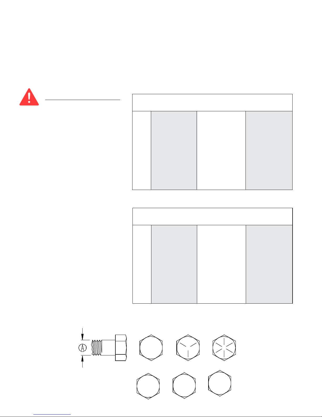
BOLT TORQUE
TORQUE DATA FOR STANDARD NUTS, BOLTS, AND CAPSCREWS.
Tighten all bolts to torques specified in chart unless otherwise noted. Check tightness of bolts periodically, using
bolt chart as guide. Replace hardware with same grade bolt.
NOTE: Unless otherwise specified, high-strength Grade 5 hex bolts are used throughout assembly of equipment.
Bolt Torque for Standard bolts *
G R ADE 2 G R ADE 5 G R ADE 8
“A” lb-ft (N.m) lb-ft (N.m) lb-ft (N.m)
1/4” 6 (8) 9 (12) 12 (16)
5/16” 10 (13) 18 (25) 25 (35)
3/8” 20 (27) 30 (40) 45 (60)
7/16” 30 (40) 50 (70) 80 (110)
1/2” 45 (60) 75 (100) 115 (155)
9/16” 70 (95) 115 (155) 165 (220)
5/8” 95 (130) 150 (200) 225 (300)
3/4” 165 (225) 290 (390) 400 (540)
7/8” 170 (230) 420 (570) 650 (880)
1” 225 (300) 630 (850) 970 (1310)
Torque figures indicated are valid for non-
greased or non-oiled threads and heads unless
otherwise specfied. Therefore, do not grease or
oil bolts or capscrews unless otherwise speci-
fi e d in this manual. When using locking
elements, increase torque values
by 5%.
* GRADE or CLASS value for bolts and cap-
screws are identified by their head markings.
Torque Specifications
CLASS 8.8 CLASS 9.8 CLASS 10.9
“A” lb-ft (N.m) lb-ft (N.m) lb-ft (N.m)
6 9 (13) 10 (14) 13 (17)
7 15 (21) 18 (24) 21 (29)
8 23 (31) 25 (34) 31 (42)
10 45 (61) 50 (68) 61 (83)
12 78 (106) 88 (118) 106 (144)
14 125 (169) 140 (189) 170 (230)
16 194 (263) 216 (293) 263 (357)
18 268 (363) -- -- 364 (493)
20 378 (513) -- -- 515 (689)
22 516 (699) -- -- 702 (952)
24 654 (886) -- -- 890 (1206)
Bolt Torque for Metric bolts *
G R ADE-2 GRADE-5 GRADE-8
8.8 10.9
9.8
CLASS 8.8 CLASS 9.8 CLASS 10.9

Page 12
PTO HORSEPOWER REQUIREMENTS
PTO horsepower requirements are based on most normal dairy or beef rations. Horsepower requirements
may vary depending on the ration or material to be mixed.
Refer to tractor weight requirements for these recommendations and transporting safety precautions for ad-
ditional tractor and towing requirements.
•
•
DRAWBAR ATTACHING SYSTEM
Adjust tractor drawbar and/or the mixer clevis hitch so that the mixer is approximtely level. The top of the
drawbar should be 8”-12” below the tractor PTO shaft. Adjust the drawbar horizontally so that the hitch pin
hole is 14”-16” behind the tractor PTO and the drawbar is centered and locked into place.
A hitch pin with a minumum of 1” diameter with a retainer pin is recommended.
•
•
HYDRAULIC SYSTEM
Dual hydraulic outlets are required for operating the door and either the slide tray or the powerchute. If your
tractor has only a single set of ports, then either the 3 bank valve option or one of the 2 hose with manual
selector valve options should be ordered. On units with the power chute option, the chute hoses may be
difficult to connect due to the chute weight on the lift cylinder. Lift weight off chute cylinder to connect hoses.
Tractor hydraulic system requirements are 6 GPM @ 1500 PSI when a slide tray is used, 15 GPM @2000
PSI when a 3-auger power chute is used.
•
MIXER SETUP
Check for proper assembly, adjustment, and lubrication. Check to see that there is adequate oil in the oil bath. If
power chute is used, oil the roller chains. Check all bolt and set screws are tight.
Be sure all shields are properly in place.
Check for and remove any foreign objects in the mixer hopper and discharge opening.
Check to see that drain plugs are installed and the door is closed.
Be sure no one is inside the mixer.
• Test run the mixer.
• Make sure mixer is empty, then start the mixer.
• Run for at least five minutes at rated PTO RPM.
• Raise and lower the door and operate the chute/slide tray several times.
• Disengage the mixer and turn off the tractor engine and remove driveline.
• Check the mixer drive components to be sure they are not abnormally hot.
If any of these items are not running as indicated, immediately repair or contact your service
representative.
•
•
•
•
•
MIXER RUN-IN
To adjust the height of the power chute, change the length of the link chains on the sides of the chute. For best
performance, the unloading height should be set at the lowest height possible. The discharge tip-off on the power
chute should be adjusted for correct magnet and discharge angle. Remove or loosen the upper bolts, pivot the
tip off to the desired angles and reinstall or retighten all bolts.
•
POWER CHUTE ADJUSTMENT (OPTIONAL)
To avoid personal injury: The hopper floor may be slippery and the auger can spin unexpectedly when stepped
on. Use caution when stepping or standing inside the unit, place a protective cover over the auger knives
when work inside the box is required.

Page 13
MIXER OPERATION
Always refer to Equipment Safety Guidelines & Before Operation sections of this manual before operating this mixer.
The Turbo-Max Mixer was designed for blending dairy and beef rations. Most commonly used ingredients, including
limited amounts of dry stem hay, can be mixed quickly and uniformly in this mixer. If you have questions regarding
your feed ration or have other applications, please contact Sioux Automation Center, Inc.
The Turbo-Max Mixer mixing performance can vary greatly according to the differences in materials, loading se-
quence, mixing speed, and unloading methods.
•
•
GENERAL
When the mixer is in operation it has many moving parts which could cause severe injury or death to persons
coming in contact with these parts. To help avoid serious accidents, please read and understand this manual.
•
SAFETY
Do not load hay without other dry commodities in the mixer first to act as a carrier or “lubricant”.
Do not overload hay content, Sioux Automation Center Inc. recommends up to 15%-20% of hay by weight
in the load. Exceeding this percentage can decrease mixing performance or could potentially damage mixer and
cause premature wear on driveline components.
•
•
LIMITATIONS
Do not use tough hay (20%-60% moisture) Always used cured, dry hay. Wet hay, foreign objects or overload-
ing may cause binding and damage to the mixer.
Keep in mind the overall size of the mixer to allow clearance through doorways.
•
•
WARNINGS
The mixer can mix an average load in 3 to 5 minutes. Due to this short mixing time, there is normally no reason
to run the mixer during loading except to level the materials or to breakup hay.
•
MIXING TIME
When deciding when and how fast to operate the mixer, factors such as ingredients being used, the thorough-
ness of the mix, and the time available to mix must be considered. Normal mixing speed is 3/4 to full PTO
speed.
Do not exceed rated PTO speed. When the mixer is operated faster than rated PTO speed the strain on the drive
train and mixer is greatly increased.
•
•
MIXING SPEED

Page 14
• The following feed materials require some preparation or processing to be mixed in the Turbo-Max Mixer:
• ALL LONG AND UNCURED GRASSES
• ROUND BALES, LARGE SQUARE BALES
• SMALL SQUARE BALES
MATERIALS REQUIRING PREPERATION
Always use cured dry hay. Tough hay can cause wrapping, binding and damage to the mixer and can
adversely effect the mixing performance. The following are some examples that contribute to tough hay condi-
tions: high moisture content, high grass content, high density bales,outdoor storage, use of hay preservatives,
and excessive stem length.
•
HAY QUALITY
• Prior to loading, check mixer for foreign objects and be sure the door is fully closed.
1. Load Commodities
Adding ingredients like corn, soybean meal, cottonseed, etc. will act as a carrier or “lubricant” if hay is
included in the ration.
If there are few commodities in the ration, substituting corn silage or haylage is preferred.
Fill mixer between 1/3-1/2 full by volume in commodities and forage before adding the hay to the ration.
This will allow enough room for the hay to expand and bring feed level up so the top auger can assist in
processing.
2. Load Hay
Load processed hay. With the mixer running at 3/4 to full PTO speed, proceed loading the small square
bale pieces or tub ground hay into the mixer. Do not exceed 15%-20% of hay by weight.
3. Finish Loading Commodities
Finish loading any other ingredients to complete the ration in order of least binding ingredient to most
binding. Example: dry commodities first, corn silage second, haylage last.
4. Finish Loading Wet Commodities
Any other wet feeds may be added at this time.
5. Add Liquid Ingredients
•If ration includes water, add it last. Adding water at the beginning will cause the hay to bind.
NOTE: DO NOT OVERLOAD MIXER! Overloading causes excessive horsepower requirements, increased strain
on driveline and poor mixer performance.
•
•
•
•
•
•
LOADING AND MIXING
Many different kinds of materials can be mixed with the Turbo-Max Mixer, but each kind of material has its own
unique characteristics.
FORAGES- Chopped hay, corn silage, and finely chopped crop residue can be mixed in the mixer. Wet and
heavy forages added in large volumes may require more power to mix.
GRAINS- Ground, rolled, flaked, and whole cereal grains, minerals, and concentrates, are all very easily mixed,
and can improve the mixing performance of the other materials.
LIQUIDS- Supplements and liquid fat can be blended in the mixer. Some operators prefer adding liquids into
the empty mixer, and others add liquids on top of grains or roughage. Sticky liquids such as molasses tend to
increase the power requirements.
•
•
•
•
MATERIAL THAT CAN BE LOADED DIRECTLY INTO THE MIXER
MIXER OPERATION

Page 15
Do not overload mixer! Overloading causes excessive horsepower requirements, increased strain on mixer drive-
line and poor mixer performance.
The design of the Turbo-Max Mixer requires that there be adequate space to allow the feed to move in and around
the reel chamber. If the reel is completely covered, it cannot efficiently mix the materials. The reel cross tubes
should always be visible at the top of their rotation to allow this mixing space.
•
•
FILL LEVEL
After the ration has been thoroughly mixed, open the mixer door to begin unloading. If the mixer is equipped
with a power chute, the chute must be running before the mixer door can be opened. The combination of the
discharge door opening and the mixer speed determines the flow of feed from the mixer. The door must be
opened far enough to prevent separation of materials, optional door flow control plates are available to help pre-
vent separation. To stop the flow of feed, close the door, (turn off the power chute) then shut off the mixer.
The Turbo-Max Mixer can be equipped with either a power chute, or a slide tray to assist in the delivery of
feed. The chute and tray heights are adjusted with hydraulic cylinders, but the chain stops provided on power
chutes should be adjusted so that the chute clears all bunks, obstacles, etc.
•
•
UNLOADING
MIXER OPERATION
INSPECTION AND ADJUSTMENTS
IMPORTANT! READ BEFORE OPERATING MIXER. IT IS THE RESPONSIBILITY OF THE
OWNER TO MARE SURE THE MIXER IS SET UP PROPERLY. THE FOLLOWING RECOM-
MENDATIONS SHOULD BE HELPFUL
Roller Chain Tighteners so they apply sufficient spring tension to keep roller chains running smoothly (As
a general rule the thickness of a nickel should fit between the spring coils). The chain will form grooves in the
tightener blocks. These grooves help to keep the chains in proper alignment, and the blocks need not be turned
unless the roller portion of the chain has worn into the block.
Roller Chains for wear, proper alignment and tension. Adjust or replace if necessary. Roller chain connector
links which pass over polyethylene tightener blocks must have the legs of the cotter pins trailing to the direction
of rotation.
Safety Decals for readability. If any safety decals are removed, obstructed, or otherwise not understandable,
they should be replaced immediately. Keep all decals clean and visible.
Safety Shielding to be sure all shielding is in place and functions properly. Replace all damaged or missing
shielding immediately - see parts pages for more information.
Bolts and Set Screws after a few hours of use and each month thereafter. Tighten if necessary.
Reel Wipers plastic strips which help material clean out of the reel hopper. If the strips become bent back, they
can be unbolted and turned around or replaced to improve clean out.
Upper Auger Knives can be turned over for use on a new cutting edge and should be periodically sharpened,
or replaced if they are no longer sufficiently breaking up material.
Lower Auger Round Knives can be rotated several times before sharpening or replacement is required.
Discharge Chute Augers (optional) to keep from rubbing on the chute body: There are shims behind each
chute auger bearing for alignment. Periodically check chute liners for wear, replace as necessary.
Trailer Hitch for proper location, alignment and tightness of attaching bolts. If the upper clevis bar becomes
excessively worn the hitch assembly should be unbolted and replaced as necessary. Frequently check the clevis
attaching bolts for tightness, and that the clevis is secure. Worn or damaged bolts must be replaced.
•
•
•
•
•
•
•
•
•
•
INSPECT AND ADJUST

Page 16
Wheel Bolts must be kept properly torqued. Damage to the rim may occur if wheel bolts are not checked fre-
quently.
8-bolt rim: 170 ft lbs-Grade 8 Lug
10-bolt rim: 300 ft lbs-Grade 8 Lug
Tire Wear and Pressure must be checked to ensure that there is no excessive wear, and that tires are inflated
to the recommended operating pressure for each given tire.
Rain can accumulate in mixer if stored outside, always remove drain plugs on hopper ends to allow unit to
drain completely and replace drain plugs before next use.
Freezing Weather the PTO shield requires extra grease to prevent freezing. Snow can accumulate in mixer
if stored outside, always remove drain plugs on hopper ends to allow unit to drain completely and check hopper
for snow or ice buildup before operating unit. Thaw and remove any obstruction and replace drain plugs before
next use.
IMPORTANT: WHEN WELDING ON THIS UNIT: Do NOT allow the current to flow through the bearings,
roller chains, or scale weigh bars. Ground directly to the item being welded. ALWAYS disconnect weigh bar cords
from scale indicator before welding.
•
•
•
•
INSPECT AND ADJUST
INSPECTION AND ADJUSTMENTS
Scale Indicator: Refer to the electronic scale operators manual for adjustment information. The operator’s
manual for the Electroic Scales should be kept with this manual. Additional scale manuals may be obtained
through Sioux Automation Center, Inc.
Load Cells: Should be kept clean, dry,and lubricated to insure dependabiltiy.
Normal Scale Activity: Some warm up scale “drift” may occur after the scale is turned on but should zero
balance within 10-15 minutes. Scale may zero shift over night due to temperature changes.
•
•
•
ELECTRONIC SCALES
Page 17
It is extremely important that the following lubrication schedule be followed: Bearings: use a good
quality multipurpose grease. Replace all damaged or missing grease zerks immediately. Always clean zerks
before using grease gun. Pump the grease in slowly until a slight bead forms around the bearing seals. Once
a month check lines and connections on grease banks for leaks.
Oilbath Oil: Use a good high quality universal oil. Use an oil that meets or exceeds hydraulic oil grade. Fill
to the top lower oilbath roller chains. Change yearly or whenever contaminated.
Before operating a new mixer, the roller chains should be liberally lubricated and then the unit operated un-
der a no-load condition. This break-in period will allow the roller chains to be thoroughly lubricated and thus
minimize heat-up during operation.
•
•
•
LUBRICATION
INTERVAL COMPONENTS
1 8-10 HOURS
REAR AUGER BEARINGS (6 ZERKS, 3LH & 3RH)
INPUT SHAFT HANGER BEARINGS (4 BEARINGS)
PTO JOINTS (2) AND SLIDE
FRONT AUGER BEARINGS (2 BEARINGS)
DISCHARGE BEARINGS (IF APPLICABLE) AND PIVOTS
2 20 HOURS
DOOR GUIDES AND PIVOTS (SPRAY LUBRICANT)
WHEEL BEARINGS (2)
DISCHARGE CHAINS (IF APPLICABLE)
3 50 HOURS OIL BATH (CHECK LEVEL)
4 ANNUAL REPACK WHEEL BEARINGS
DRAIN AND REPLACE OIL BATH OIL
,)$33/,&$%/(
Page 18
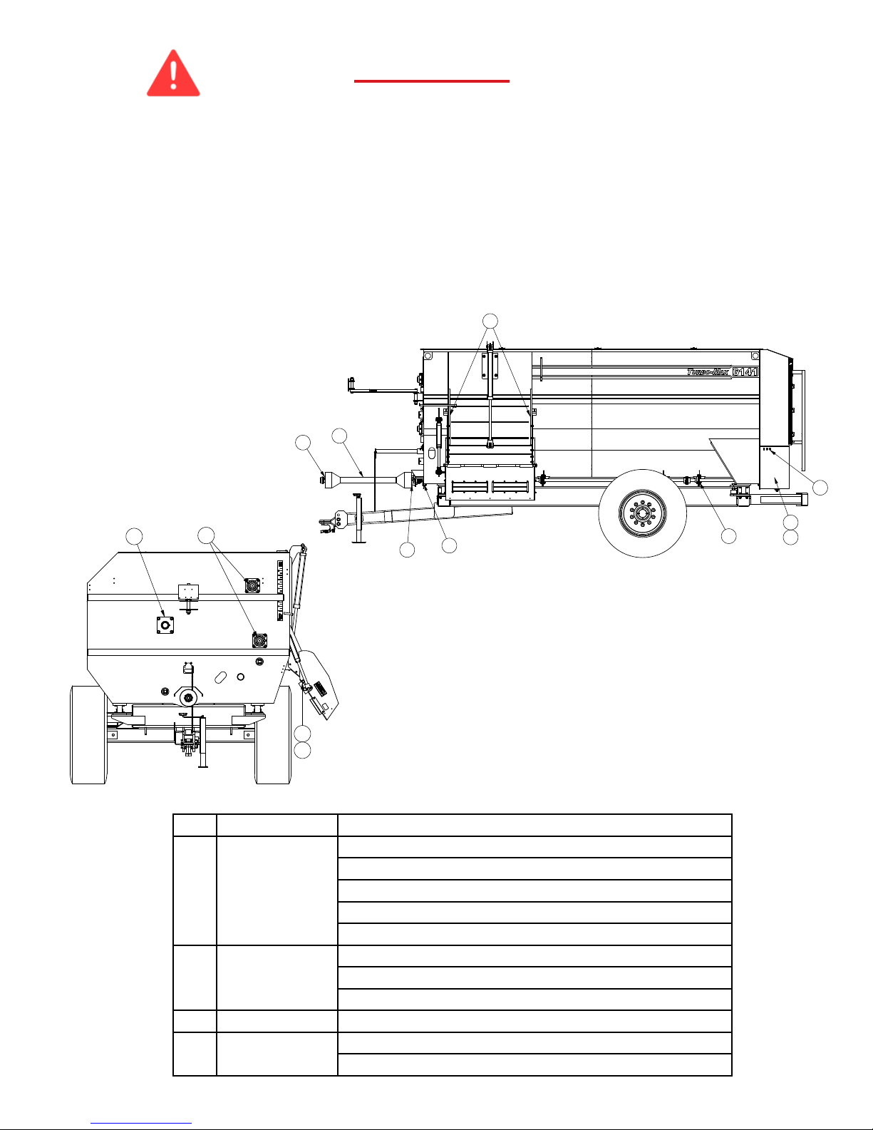
DECAL LOCATION
ITEM
#
6141
QTY.
PART # DESCRIPTION
1 9 DEC102 DECAL,GRS,GUN,PICTURE
2 5 DEC105 DECAL,DANGER,DRVLN,ROTATE
3 1 DEC106 DECAL,CAUTION,MAN,OWNER,5,6
4 1 DEC107 DECAL,WARNING,CHAIN,EXPOSED
5 1 DEC108 DECAL,WARNING,PART,MOVING,4,4
6 1 DEC109 DECAL,CAUTION,WLD,3,3
7 4 DEC111 DECAL,DANGER,AUGER,5,6
8 1 DEC114 DECAL,4AUG,OPEN/CLOSE
9 1 DEC154 DECAL,SAC,LOGO,NEW,20.5H,24W
10 1 DEC375 DECAL,MODEL,SERIAL,SAC,2.75,5
11 1 DEC393 DECAL,FEMA,1.5,2.5
12 2 DEC322 DECAL,WARNING,CHUTE,AREA
13 2 DEC431 DECAL,TURBOMAX,6141,WHITE
14 1 DEC452 DECAL,TM,6.75,168,CS
15 1 DEC453 DECAL,TM,6.75,114,SS
16 80 DECREFLECTAPE TAPE,RFLCTV,2”,RED,WHT
17 1 DECSMV DECAL,VEHICLE,SLOW,MOVE,VINYL
18 2 STI702174 REFLCTR,RECT,AMBER
19 2 STI702175 REFLCTR,RECT,RED

Page 19
TURBO-MAX TRAILER SPECIFICATIONS
MODEL 6129 6135 6141 6150 6160 6170
DIMENSIONS (INCHES)TRAILER TRAILER TRAILERTRAILER TRAILER TRAILER
A - Overall Length 197 220 247 248 278 308
B - Mixing Chamber Length 120 144 168 168 198 228
C - Front Discharge to Bumper 119143181183 213 243
D - Overall Height192/99497 104 114114114
RH Drop Side Reduction1414 14 14 14 14
E - Tread Width 87 99 100 100 100 103
F - Overall Width (mixer only) 92 92 92 102 102 102
G - Slide Tray - max. reach 181918 18 18 18
- Power Discharge - max reach 2/3537/47 38/48 37/47 37/47 37/47 37/47
H - Slide Tray - max. height122/29428 35 32 32 32
- Power Discharge - max height 2/3532/39 39/46438/45 45/52 42/49 42/49 42/49
I - Slide Tray - transport width 104 107 107 114114114
- Power Discharge - transport width 2/35118/118 121/121 121/121 132/132 132/132 132/132
J - Hinge height for discharge133/40439 46 50 50 50
SPECIFICATIONS
Unit Weight - pounds 9500 12000 13000 16000 18500 21000
Maximum Net Load - pounds 8700 10500 12300 15000 18000 21000
Mixing Capacity - cubic feet 290 350 410 500 600 700
Reel Diameter 62 62 62 70 70 70
Reel Tube - Outside Diameter 6-5/8 6-5/8 6-5/8 8-5/8 8-5/8 8-5/8
Reel Arms 3-1/2 3-1/2 3-1/2 4 1/2 4 1/2 4 1/2
Reel Hopper Thickness 5/16 5/16 5/16 3/8 3/8 3/8
Reel Speed RPM7.1 7.1 7.1 6.5 6.5 6.5
Lower Auger
Flighting Diameter 20 20 20 24 24 24
Flighting Thickness - Sectional21/2 1/2 1/2 5/825/825/82
Tube - Outside Diameter 5-9/16 5-9/16 5-9/16 6-5/8 6-5/8 6-5/8
Drive Shaft Diameter 3 3 3 4 4 4
Upper Auger
Flighting Diameter 20 20 20 22 22 22
Flighting Thickness - Sectional 3/8 3/8 3/8 1/2 1/2 1/2
Tube - Outside Diameter 5-9/16 5-9/16 5-9/16 6-5/8 6-5/8 6-5/8
Drive Shaft Diameter 3 3 3 3.5 3.5 3.5
Auger Hopper Thickness 5/16 5/16 5/16 3/8 3/8 3/8
Side Sheet Thickness 1/8 1/8 1/8 3/16 3/16 3/16
End Sheet Thickness 1/4 1/4 1/4 1/4 1/4 1/4
Door Opening Size
32.63X20.25 32.63X20.25 40.75X20.50 40.75 x 21.50 40.75 x 21.50 40.75 x 21.50
Roller Chain Drive 60-80-100 80-100-120 80-100-120 100-120-140-160 100-120-140-160 100-120-140-160
Spindle Diameter 2-1/2 3-3/8 3-3/8 3-3/8 3-3/8 3-3/8
Hub HD 8 bolt HD 10 bolt HD 10 bolt HD 10-bolt HD 10-bolt HD 10-bolt
Ton gue Weight - % of gross weight empty/full6% / 10%6%/ 10%6%/ 10%6% / 10%5%/ 8% 5% / 8%
Minimum Horsepower Requirement - PTO360 80 90 100 110120
PTO Speed 540 540 540/1000 1000 1000 1000
1 Heights and widths will vary with tire size.
2 Lower auger ! i ghting at convergence is 3/4 standard.
3 Horsepower requirements will vary by ration components and moisture.
4 Shorter heights based on 225/70x225 tire in low axle position,
Tal ler heights based on 1100x225 tire in high axle position.
5 6126 & 6135 models use 3-auger discharge, all others use 4-auger.
&
$
%
'
-
)
(*
+
,

Page 20
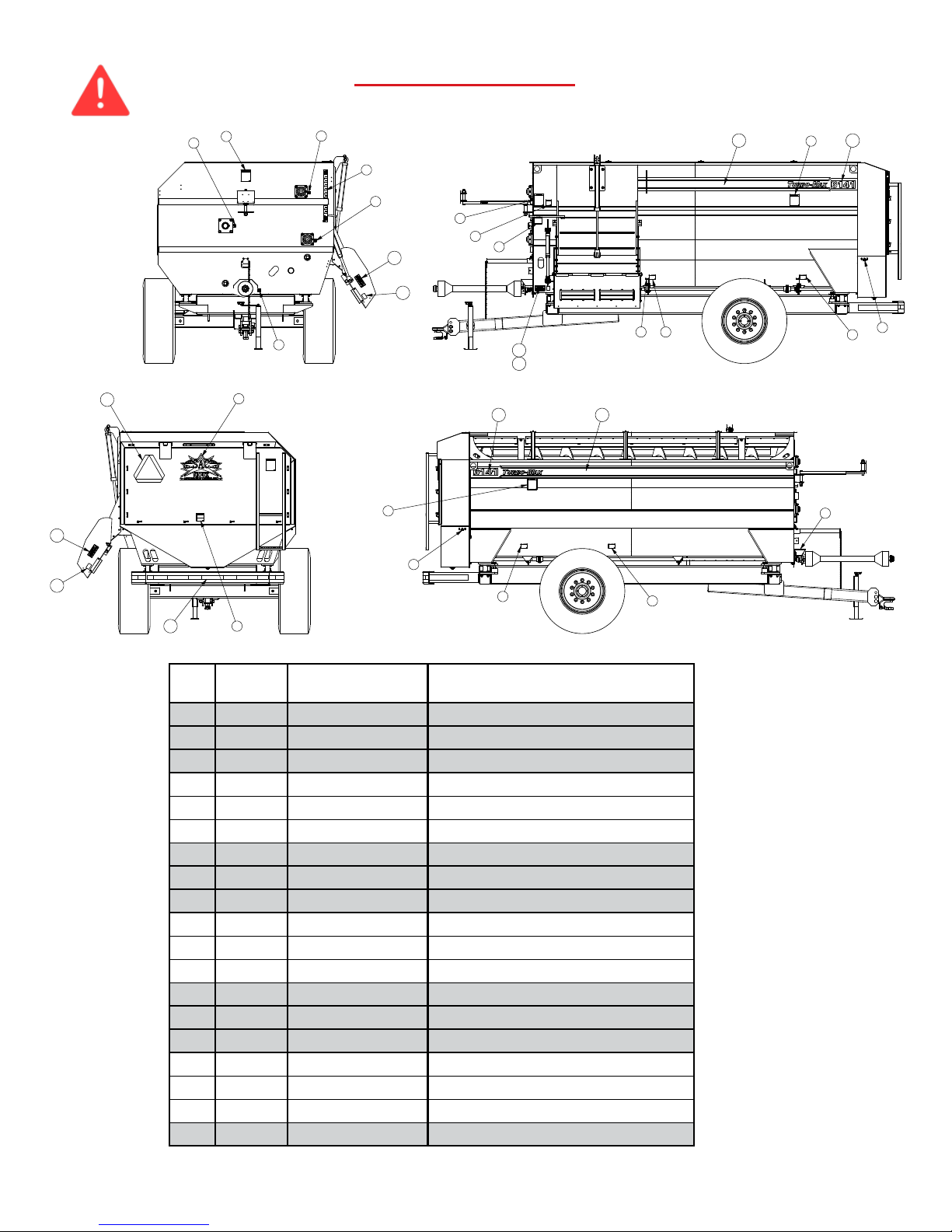
6141 BOX BASE ASSEMBLY BILL OF MATERIALS
(MON900728-2)
ITEM # QTY PART # DESCRIPTION
1 26 BLT12X112NC 1/2X1-1/2 BOLT
2 4 BLT12X114NC 1/2X1-1/4 BOLT
3 4 BLT12X3NC 1/2X3 BOLT
4 3 BLT12X4NC 1/2X4 BOLT
5 16 BLT1X312NC 1X3-1/2 BOLT
6 4 BLT34X112NC 3/4X1-1/2 BOLT
7 20 BLT34X212NC 3/4X2-1/2 BOLT
8 2 BLT34X2NF 3/4X2 BOLT
9 16 BLT34X3NC 3/4X2 BOLT
10 3 BLT38X134NC 3/8X1/3/4 BOLT
11 176 BLT516X114NC 5/16X1-1/4 BOLT
12 9 BLT516X1NC 5/16X1 BOLT
13 2 BLT516X34CNC 5/16X3/4 CARRIAGE BOLT
14 4 BLT58X114NC 5/8X1-1/4 BOLT
15 8 BLT58X212NC 5/8X2-1/2 BOLT
16 2 BRGFB22448H 4 FLANGE BEARING
17 2 BRGRCJ138 1.38 FLANGE BEARING
18 2 BRGRCJ2 2 FLANGE BEARING
19 2 BURN12000305 4.5 SPROCKET RETAINER DISK
20 1 KEY516X112 5/16X1-1/2 KEY
21 1 MON101201 SEAL RETAINER
22 2 MON102684 TIGHTENER ARM
23 2 MON102704 .5 HINGE PIN
24 1 MON102801 SPROCKET
25 1 MON102837 3-1/2 PIPE X 3.25
26 1 MON102874 120-H ROLLER CHAIN (135P)
27 1 MON102875 100-H ROLLER CHAIN (75P)
28 1 MON102876 80-H ROLLER CHAIN (159P)
29 2 MON102883 FLANGE
30 1 MON102887 TIGHTNER ARM
31 1 MON102888 INPUT SHAFT
32 1 MON102890 SLEEVE SPACER
33 2 MON102891 BEARING SEAL
ITEM # QTY PART # DESCRIPTION
34 1 MON102892 SLEEVE SPACER
35 4 MON102893 THRUST WASHER
36 2 MON102894 SEAL RETAINER
37 1 MON102919 BEARING SEAL
38 1 MON103191 COVER PLATE
39 23 MON300018 ROUND AUGER KNIFE
40 3 MON300026 CHAIN TIGHTNER
41 3 MON300029 SPRING
42 2 MON300079 LIFT SHOCK
43 4 MON300080 LIFT SHOCK STUD
44 1 MON700916 SPROCKET
45 1 MON701128 SPROCKET
46 1 MON701130 SPROCKET
47 1 MON701134 REAR DOOR
48 1 MON701135 CYLINDER BRACKET
49 1 MON701140-2 6141 BODY WELDMENT
50 3 MON701154 BUCKET GUARD
51 2 MON701156 DISCHARGE DOOR
52 1 MON701279 FLANGE SHAFT
53 1 MON701280 FLANGE SHAFT
54 1 MON701281 BOTTOM AUGER
55 1 MON701282 TOP AUGER
56 1 MON701303 FLANGE SHAFT
57 1 MON800488 SPROCKET
58 1 MON800531 MANUAL CANISTER
59 1 MON900724 REEL BEARING
60 1 MON900824 REEL ASSEMBLY
61 37 NUT12NC 1/2” NUT
62 8 NUT1LOCKNC 1” LOCK NUT
63 8 NUT1NC 1” NUT
64 16 NUT34LOCKNC 3/4” LOCK NUT
65 24 NUT34NC 3/4” NUT
66 3 NUT38LOCKNC 3/8” LOCK NUT
ITEM # QTY PART # DESCRIPTION
67 2 NUT516LOCKNC 5/16” LOCK NUT
68 185 NUT516NC 5/16” NUT
69 12 NUT58NC 5/8” NUT
70 10 OSW830212 DOOR LATCH
71 1 RC100HCON 100-H CONNECTOR LINK
72 1 RC120CON 120-H CONNECTOR LINK
73 1 RC80HCON 80-H CONNECTOR LINK
74 88 SAC73026 SICKLE KNIFE
75 88 SAC73207 KNIFE SUPPORT
76 1 SAC75008 FRONT REEL BEARING
77 1 SELCR13536 OIL SEAL
78 6 SPBUS3WR14G 14 GA BUSHING
79 4 SPCP18X1 1/8” COTTER PIN
80 1 SPGH24 GREASE HOSE
81 2 SPGH48 GREASE HOSE
82 2 SPGH60 GREASE HOSE
83 5 SPGZRK618 GREASE ZERK
84 3 SPHKE38 TURNBUCKLE
85 1 SPK80B13X138 SPROCKET
86 1 SPM1693R LIGHT BAR
87 1 SPOSRG138HD SNAP RING
88 3 SPSCL1 SHAFT COLLAR
89 2 STI701748 RED CLEARANCE LIGHT
90 11 WSH12FLAT 1/2” FLAT WASHER
91 37 WSH12LOCK 1/2” LOCK WASHER
92 1 WSH1FLAT 1” FLAT WASHER
93 8 WSH1LOCK 1” LOCK WASHER
94 26 WSH34LOCK 3/4” LOCK WASHER
95 3 WSH38FENSS 3/8” FENDER WASHER
96 9 WSH516FLAT 5/16” FLAT WASHER
97 185 WSH516LOCK 5/16” LOCK WASHER
98 12 WSH58LOCK 5/8” LOCK WASHER
Table of contents
Popular Utility Vehicle manuals by other brands

swaploader
swaploader SL-145 Parts and operation manual

Linhai
Linhai Crossfire E5 2022 Service manual

U-Line
U-Line H-4121 quick start guide

pronovost
pronovost PUMA-347AG Operator's & parts manual

Woodland Mills
Woodland Mills MULTILANDER TRAILER Operator's manual

KidNme Motorsports
KidNme Motorsports Blade Service manual


