Tinget STE-A User manual

STE-A Steam Sterilizer
Technical Manual

1.PARTS
Water pump Steam generator Outer temperature
sensor
Vacuum pump Steam generator
thermal protector
Transformer
CONTENT
1.PARTS 1
2.ELECTRNIC DRAWING 2
3.WORKING PRINCIPLE 4
4.MALFUNCTION 5
4.1. PHENOMENA 5
4.2.FUNCTION OF THE PARTS 12
1
Inner temperature
sensor
Chamber
thermal protector

2.ELECTRICAL DRAWING
2
DOOR SWITCH
DISPLAY
DATA LINE
T12A
21V
9V
220V
FAN
OUTPUT
STEAM
HEATER
CHAMBER
HEATER
PRINTER
OUTPUT
PRESSURE SENSOR
T12A
THERMAL
PROTECTOR
THERMAL
PROTECTOR
V1 V4
KEYBOARD
DATA LINE
VACUUM
PUMP
WATER
PUMP
V2 V3 V5
TP 1
TP 3
TP 2
TANK MAX. LEVEL
TANK MIN. LEVEL
PUBLIC
USED WATER TANK
MAX. LEVEL
(~110V)
(T20A for 110V)
(T20A for 110V)
AC220V
(AC110V)
18/23-A
TP1: Steam generator temperature sensor
TP2: Inner temperature sensor of chamber
TP3: Temperature sensor of chamber wall
V1: Air release valve
V2: Air filter valve
V3: Water pump valve
V4: Water release valve
V5: Vacuum pump valve

T12A
T12A
21V
9V
220V
PRESSURE SENSOR
AC220V
OUTPUT
FAN
WATER
PUMP
VA C U U M
PUMP
CHAMBER
HEATER
STEAM
HEATER
THERMAL
PROTECTOR
THERMAL
PROTECTOR
TP 2
TP 3
TP 1
PRINTER
OUTPUT
KEYBOARD
DATA LINE
V1 V3
V2 V4 V5
DOOR SWITCH
TANK MIN. LEVEL
TANK MAX. LEVEL
USED WATER TANK
MAX. LEVEL
PUBLIC
(~110V) (T20A for 110V)
(T20A for 110V)
AC220V
(AC110V)
7
6
5
L
N
4
12/16-A
3

4
08-A
THERMAL
PROTECTOR
STEAM
HEATER
CHAMBER
HEATER
THERMAL
PROTECTOR
WATER
PUMP
VACUUM
PUMP
FAN
V1
PRESSURE SENSOR
PRINTER
OUTPUT
KEYBOARD
DATA LINE
DOOR
SWITCH
USED WATER TANK
MAX. LEVEL
TANK MAX. LEVEL
TANK MIN. LEVEL
PUBLIC
T1
220V
V5
V2
V4
V3
21V
11V
T12A
T12A
220V
T2
T3
(~110V)
(T20A for 110V)
(T20A for 110V)
AC220V
(AC110V)

4.1 Phenomena
There is no action after power on.
Make sure the light of power switch is on. If it is not, make sure the power plug contact the
socket well.
If the power socket is ok ,Check the main fuse.
Power
Main fuse
Check the output of the transformer, the couple of green wire is 1 24 ,the other is
blue-black -gray
2V
15- 0- 15V
Transformer
Solution
4.Malfunction
Please mark down the alarm code and phenomena when it appears alarm. If there is emergency or serious
thing you may power off. And open the door when the pressure inside the chamber is less than 0.05 bar.
In the others situation you better holding the START button to stop the program manually. That the
system will stop the current program and drain the water inside the chamber.
’d
5
E1
E3
Alarm condition: Steam generator overheats, or temperature sensor doesn't work.
E2
Alarm condition: the inner chamber overheats, or temperature sensor doesn't work.
Alarm condition: the chamber wall overheats, or temperature sensor doesn't work.
Case 1: Overheating of steam generator:
Solution: Shut off the power, open the door and wait for 10 minutes. And then power on
you may use it again if the alarm disappear.
Case 2: Shut off the power. Then power on, if it alarm right away. The cable between the
sensor of steam generator and mainboard is disconnected, or the sensor had been
destroyed.
Solution: Shut down the power, check if the cable of steam generator sensor is connected well.
If it connect well you shall replace sensor.
Case 3: The controlled temperature by thermal protector of steam generator is too high.
Solution: Please try to turn the thermal protector anti-clockwise with a small angle, less
than 5 degree, and then try to run the cycle again.
Case 1: Overheating of inner chamber
Solution: Shut off the power, open the door and wait for 10 minutes. And then power on, you
may use it again if the alarm disappear.
Case 2: Shut off the power. Then power on, if it alarm right away. The cable between the inner
sensor and mainboard is disconnected, or the sensor had been destroyed.
Solution: Shut down the power, check if the cable of inner sensor is connected well.
If it connect well you shall replace sensor.
Case 1: Overheating of chamber wall
Solution: Shut off the power, open the door and wait for 10 minutes. And then power on,
you may use it again if the alarm disappear.

6
Case 2: Shut off the power. Then power on, if it alarm right away. The cable between the
chamber wall sensor and mainboard is disconnected, or the sensor had been destroyed.
Solution:Shut down the power, check if the cable of chamber sensor is connected well.
If it connect well you shall replace sensor.
Case 1: Before appear E4, the temperature had never reached to 135 , and the pressure is
over 225kpa, and release steam frequently.
Solution: Please check the altitude set, normally adjust to "+1" (Please refer the instructions manual)
Case 2: Before appear E4, the pressure is lower than 10kpa, and temperature is around 100 or less than.
Solution: Please check the air release valve, if it is working normally.
Case 3: When appear E4, the temperature is below . There is no steam inside the chamber.
Touch the top inside the chamber, feel the temperature is not too high.
Solution: Check the chamber heater whether it works. Does the cable connected well?
Does the chamber wall temperature protector work?
Case 4: When appear E4 the temperature is below 100 .There is no steam inside the chamber.
Restart the machine. Waiting for 15 minutes. Check the indicator light of steam generator
indicator light on the mainboard. The light is blinking. Or it haven't enter the pre vacuum
stateifitisclassB.
Solution: Check the steam generator works. Check the cable of the heater. Check the cable on the
steam generator protector. Check the steam generator protector works. Check the heater
of steam generator.
Case 5: When appear E4, the temperature is below 100 . There is no steam inside the chamber.
Restart the machine. Wait for 15 minutes. Check the indicator light of steam generator indicator
light on the mainboard. The light does not blink or for a long interval. Or the pre vacuum state
hadfinishedifitisclassB.
Solution Check the water pump, check the cable of water pump. Check the water pump valve V3.
Case 6:When appear E4, the temperature is higher than 100 . The pressure is higher than 0.2bar.
Solution: Check the heater of steam generator. Check if there is a big leakage on the steam generator.
Check the water release valve V4 and air release valve V1, if they can be closed completely.
You may observe the tube before the valve when the program is running and the pressure is
higher than 0.2bar.
If the valve have not been closed completely you will find the steam or water flow to
condenser continuously.
Check if there is a big leakage on the steam generator. Or in the other place
Case 7 There is a big leakage. Found some steam or steam leak when the sterilizer works.
Solution Replace the part.
Please check if the air release valve seize up
Solution: Please do not force opening the door under the state of high pressure.
Shut down the power, if the steam pressure is not released, it means the air release valve is
blocked. Turn on the power, waiting for its cooling until the pressure value is zero, or pull the
safety valve to release the pressure. Then open the door, replace the air release valve V1.
E4
E5
Alarm condition: It spent too long time to reach the holding state, normally over 1 hour
after starting a cycle, it will appear E4.
Alarm condition: Fail to release the pressure
50
E6
E7
E9
Alarm condition: The door handle was not turned to the end position, and the door handle
turn back when pressure rising.
Alarm condition: Overtimes
Alarm condition: Holding temperature is failed
Solution: Turn the door handle to the end and run a cycle again. If it still appears E6 again, please
check if the door goes down, if yes, the door has to be readjusted. To make the door be horizontal.
Solutions: the same as E4
Case 1: Adjust the parameter refer the instructions manual if in a high altitude place.
Case 2: Check the heater of steam generator. One of the heaters does not work.
Case 3: Check if there is a big leakage on the steam generator. Or in the other place
Case 4: Check the water release valve V4 and air release valve V1, if they can be closed completely.
You may observe the tube before the valve when the program is running. If the valve have
not been closed completely you will find the steam or water flow to condenser continuously.
EF
Alarm condition: System have not initialized
Usually it is caused by the interference from the power net. The data saved in the chip is lost.
We need to reset the data. And after reset the data. We recommend using the manostat to avoid
interference.
7
Correct the parameter of sensor for 18/23-A
1. Power off
2. Open the cover of machine
3. Replace the 3 temperature sensors by the standard sensor.
4. Power on. And open the door.
5. Holding the SET button until you enter the menu. Release the button.
6. Select PT by press the SELECT button.
7. Press SET button. You will heard one long sound and four short sound.
That means the operation is success.
8.Press START button. Power off and replace the sensors.

1 Power off. Pull out the temperature
senor on the mainboard.
.
Replace it by the standard sensor
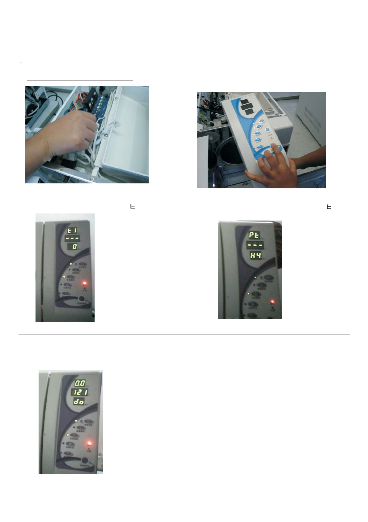
Correct the parameter of sensor for 12/16-A
2. Press the START button before Power on.
Then holding the button for about 30 seconds until
you heard a sound of di di
3. The pressure display will show .14. Press the COTTON button to adjust to P as the
picture.
5. Press the SOLID
button. Then you will heard a long sound and four
short sound. That means the adjustment success.
Make sure the door is opening. 6. Press the START button. Then power off. And replace
the standard sensor with the temperature sensors.
8
1 Power off. Pull out the temperature
senor on the mainboard.
.
Replace it by the standard sensor
Correct the parameter of sensor for 08-A
2.Replace the control panel with the standard panel.
Press the START button before Power on.
Then holding the button for about 30 seconds until
you heard a sound of di di
3. The pressure display will show .14. Press the COTTON button to adjust to P as the
above picture.
5. Press the SOLID
button. Then you will heard a long sound and four
short sound. That means the adjustment success.
Make sure the door is opening. 6. Press the START button. Then power off. And replace
the standard sensor with the temperature sensors.
9

Lots of water remains in chamber wall after cycle end.
1. The filter screen on the internal bottom of chamber was blocked
Solution: Take it out, and clean or replace it.
2. The filter screen inside the pipe before the water release valve.
Solution: Replace the filter screen.
3. The water release valve is blocked or does not work.
Solution: replace the water release valve.
E20
Alarm condition: The cycle is interrupted by manual
Solution: Shut off the power and restart the power.
10

1. Press the START button before Power on.
Then holding the button for about 30 seconds
until you heard a sound of di di
2. The pressure display will show .1
3. Press the SOLID button to adjust to 1 as
the picture. WRAPPED button for minus. 4. Press START button after set the data.
Then power off.
Altitude set for 12/16-A
Replace the control panel by the standard panel. Then the step is the same as the 16-A.
Altitude set for 08-A
11
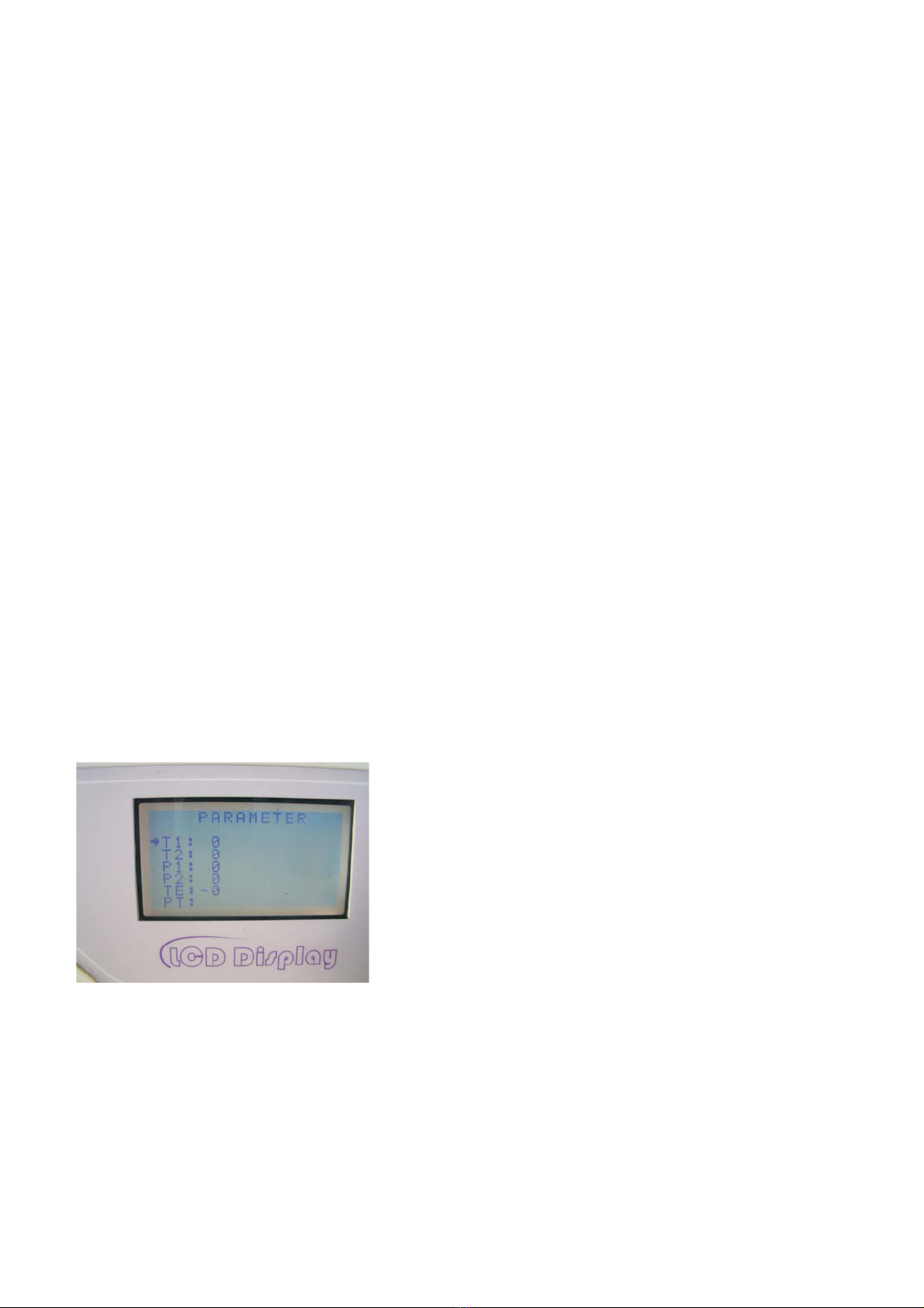
Altitude set
1. Holding th SET button until you enter the menu. Release the button.
2. Select T1 by press the SELECT button.
3. Adjust T1 to 1 or 2(base on the altitude of the location) by UP DOWN button.
4. Press START to exit .
Altitude set for 18/23-A
Caution:T2,P1,P2, TE should be 0

4.2 Function Of The Parts
1. Steam generator
The steam generator is composed of body, temperature sensor, thermal protector.
Replace the steam generantor
1.Pull out the connector of No.6 and No.7.
3.Screw off the 4 bolts of the bracket of steam
generator
4.Screw off the 2 bolts of the bracket of thermal
protector.
5.Dismantle the tube connected to the water pump and chamber.
6.Then you may pull out the steam generator and replace it.
2.Pull out the connector of TP1
Bracket of steam generator Bracket of thermal protector
7
6
clip
Caution You must press the clip of the connector when you pull out the wire No.6 and No.7.
12
pin
You will find that it is wet around the steam generator. If it is serious the pressure will not
rise. The seal ring is destroyed or the screw is loose.
The heater does not work.
Pull out the No.6 and one of the No.7 cable. Measure
the resistance of the heater. The resistance should be about
75 12/16/18L 78 8L between the No.6 and No.7.
The thermal protector does not work. It will break the power
of the heater.
Check if it is broken between the two pins. Short circuit is normal.
Can not heat
The temperature sensor short circuit or break. Measure the resistance of the senor (No.1).
The normal resistance is1000 1700 .
Leak
Sensor problem

2. Inner temperature sensor
If the sensor does not work it will appear alarm E1 You may measure the resistor . The normal
resistance is 1000 1700
Replace the outer temperature sensor
1. To find the position of the sensor and cut the
heat insulation.
2.Unfasten the brass wires.
3. Replace the sensor.
3. Outer temperatue sensor
4. Chamber thermal protector
The protector will act when the chamber heater overheat. It will cut the circuit of the chamber heater.
This protector need to be recovered by manual. After the chamber is cooled down you may press the
reversion button to recover the protector.
1.Open the cover of the machine.
sensor
2. Turn the senor anticlockwise
by spanner 12#.
To unscrew
3. Replace a new one.
Youmustscrewittightly.
Outer temperature
sensor
Brass wires
Reversion button Fixed nut
Replace the chamber thermal protector
1.
2.Pull out the connector
3.screw off the nut and replace the protector
To find the position of the sensor and cut the
heat insulation.
13
If the sensor does not work it will appear alarm E3 You may measure the resistor . The normal
resistance is 1000 1550

5. Water release valve
Water release valve is a normal close valve.
Problem1: The valve can not close completely you will see the steam and water flow by the pipe.
Problem2: The valve can not open during the period of releasing the pressure. There is much water left
after the cycle.
Check the solenoid coil if it can work. Check the circuit of water valve by multimeter. Check if the circuit is
break. Or you may measure the solenoid coil directly as picture. The resistance is about 80 .
Steam flow
14
6. Air release valve
Air release valve is a normal open valve.
Problem1: The pressure can not be released after power off if the valve does not work.
Problem2: The valve can not close completely after it is electrified. The pressure will not rise during the period
of raising pressure. And you will see the steam and water flow by the pipe.
Check the solenoid coil if it can work. Check the circuit of water valve by multimeter. Check if the circuit is
break. Or you may measure the solenoid coil directly as picture. The resistor is about 80 .
7. Vacuum pump valve
Problem : The air leak from used water tank by the valve when vacuum pump is working. And the pressure can
not decrease.
Check the solenoid coil if it can work. Check the circuit of vacuum pump from mainboard to valve by multimeter.
Check if the circuit is break. Or you may measure the solenoid coil directly as above picture.
The resistor is about 80 .
8. Vacuum pump
Check the vacuum pump works or not. Pull out the connector from the mainboard.
Measure the resistance of the vacuum pump.
The value should be 200k ohm~400ohm.
It depends on different type of the vacuum pump.

10. Door switch
11. LCD
Replace door switch
1.Open the cover of the machine, pull out the data line of LCD.
2.Dismantle the plastic cover of the LCD you will see the switch
3.Screw off the bolts to replace the door switch.
18L/23L
1.Open the cover of the machine pull out the data line of LCD.
2.Dismantle the plastic cover of the LCD fixed by 6 bolts)
3.Then you will see the LCD
If the door switch does not work, the door close icon on screen will not appear
15
If the water level sensor works. The two pins shall be short circuit
if the distilled water tank is lack of water. As the picture.
12. W distilled water tankater level sensor of the
9. Water pump
If the water pump does not work the water can not jet into the seam generator, and can not generate the
steam ,and the pressure can not rise.
Check the water pump works or not. Pull out the connector
from the mainboard.
Measure the resistance of the vacuum pump.
The resistance should be less than 1k ohm.
If the water level sensor works. The two pins shall be short circuit
if the tank is full.
13. W water tankater level sensor of the used
Table of contents
Popular Laboratory Equipment manuals by other brands

StatSpin
StatSpin ThermoBrite S500-12 Service manual

Thermo Scientific
Thermo Scientific Compact Digital Rocker user manual

RADWAG
RADWAG UYA 4Y PLUS Startup guide

Snow Performance
Snow Performance 20001 installation instructions

MBRAUN
MBRAUN LABmaster pro sp operating manual

Festo
Festo MPS 8066209 operating instructions


Dectris
Dectris PILATUS 300K-W Technical Specifications and Operating Procedure

Labconco
Labconco Fiberglass 30 Series user manual

ICANCLAVE
ICANCLAVE STE-23-D instruction manual

Thermo Scientific
Thermo Scientific RIIDEye X-G Installation, operator and technical manual

VOLTCRAFT
VOLTCRAFT LSP-2165 operating instructions

Metrohm
Metrohm 860 KF manual