StatSpin ThermoBrite S500-12 User manual

T
T
Th
h
he
e
er
r
rm
m
mo
o
oB
B
Br
r
ri
i
it
t
te
e
e
Service Manual

Service Manual
ThermoBrite
Model Number S500-12/S500-24
FOR IN VITRO DIAGNOSTIC USE
StatSpin is a registered trademark of StatSpin Inc., a Subsidiary of IRIS International, Inc.
Copyright 2004
Printed in U.S.A.

i
Table of Contents
Table of Contents............................................................................................................ i
How to use this manual.....................................................................................iii
Section 1.............................................................................................................1
Safety................................................................................................................................. 1
Before you Begin...................................................................................................... 1
Install System............................................................................................................ 1
Connect Power ......................................................................................................... 1
Section 2.............................................................................................................2
System Overview ........................................................................................................... 2
Principle and Intended Use .................................................................................... 2
Symbols and Definitions.......................................................................................... 2
Symbols and Definitions (cont.) ............................................................................. 3
Display Abbreviations .............................................................................................. 3
Audible Indicators - NORMAL ................................................................................ 3
Audible Indicators - ERROR................................................................................... 3
Error Messages ........................................................................................................ 4
Section 3.............................................................................................................5
Operating Instructions.................................................................................................. 5
Opening and Closing the Lid .................................................................................. 5
Turning Unit On ........................................................................................................ 5
Run a Denaturation and Hybridization Program ................................................. 5
Abort Program in Process....................................................................................... 7
Slide Installation ....................................................................................................... 7
Humidity Control Cards ........................................................................................... 7
Predefined Limits...................................................................................................... 7
Section 4.............................................................................................................8
Specifications ................................................................................................................. 8
Table........................................................................................................................... 8
Section 5.............................................................................................................9
Theory of Operation ...................................................................................................... 9
Overview.................................................................................................................... 9
Data Acquisition........................................................................................................ 9
Calibration ................................................................................................................. 9
PID............................................................................................................................ 10
Section 6...........................................................................................................11
Alignment....................................................................................................................... 11
Materials .................................................................................................................. 11
Workstation Setup.................................................................................................. 11
Procedure ................................................................................................................ 11
Calibration ............................................................................................................... 12
Testing ..................................................................................................................... 13
Section 7...........................................................................................................15
Programming................................................................................................................. 15

ii
Overview.................................................................................................................. 15
Character Selection ............................................................................................... 15
Creating a Denaturation and Hybridization Program (Denat & Hyb) ............. 15
Section 8...........................................................................................................16
Schematic....................................................................................................................... 16
Block Diagram ........................................................................................................ 16
Main PCB................................................................................................................. 17
Main PCB................................................................................................................. 18
Section 9...........................................................................................................19
Disassembly .................................................................................................................. 19
Heater Assembly .................................................................................................... 19
Housing Assembly ................................................................................................. 20
Section 10 .........................................................................................................21
Troubleshooting........................................................................................................... 21
Section 11 .........................................................................................................22
Exploded View .............................................................................................................. 22
ThermoBrite............................................................................................................. 22
Part Numbers.......................................................................................................... 23

iii
How to use this manual
This manual along with information contained on product labels should provide you with all the
information you need to operate and maintain the ThermoBrite.
Notes appear in italics to highlight information. When the information requires special attention, a
caution symbol appears next to the italicized text.
Please pay close attention to the instructions that accompany the notes and symbols as well as the
standard laboratory practices outlined by your facility and local regulatory agencies. The table below
lists all the CAUTIONS / WARNINGS for the ThermoBrite.
WARNING – Plug the instrument into a properly grounded outlet supplying the
voltage and frequency indicated on the serial number label.
CAUTION – Unplug the ThermoBrite from the wall outlet before performing
maintenance.
WARNING – Do not expose ThermoBrite to strong or concentrated acids, bases,
esters, aromatic or halogenated hydrocarbons, ketones or strong oxidizing agents.
CAUTION - Universal Precautions should be followed on all specimens, regardless
of whether a specimen is known to contain an infectious agent. (See references)
CAUTION –Risk of electric shock: The instrument contains no user serviceable
parts. Removal of housing will expose potentially lethal voltage. Refer service to
qualified service personnel.
CAUTION – Hot Surface: The interior surface of the instrument may be HOT, use
caution to avoid potential burn.
Please use the system as intended. Improper use of the ThermoBrite may cause damage to the
system, inaccurate results, or potentially void warranties.

1
Section 1
Safety
Before you Begin
READ ALL PRODUCT MANUALS AND CONSULT WITH TRAINED PERSONNEL BEFORE
ATTEMPTING TO OPERATE OR SERVICE THIS INSTRUMENT.
HAZARDS AND OPERATIONAL PRECAUTIONS AND LIMITATIONS
WARNINGS, CAUTIONS and IMPORTATANT alert you as follows:
WARNING - Might cause injury.
CAUTION - Might cause damage to the instrument.
IMPORTANT - Might cause misleading results
CAUTION: System integrity might be compromised and operational failures might occur if:
This equipment is used in a manner other than specified. Operate the instrument as
instructed in the Product Manuals.
You introduce software that is not authorized by StatSpin into the instrument. Only operate
your system with software authorized by StatSpin.
You install software that is not an original copyrighted version. Only use software that is an
original copyrighted version to prevent virus contamination.
IMPORTANT: StatSpin urges its customers to comply with all national health and safety standards
such as the use of barrier protection. This may include, but it is not limited to protective eyewear,
gloves and suitable laboratory attire when operating or maintaining this or any other automated
laboratory analyzer.
Install System
1. Place the ThermoBrite on a level surface suitable for laboratory instrumentation.
2. ThermoBrite has an intake fan located on bottom, assure no obstruction exist on intake.
3. Ensure the ThermoBrite is placed at least 12” (0.3048m) from the wall to allow for proper
cooling.
4. Position the ThermoBrite away from direct sunlight and sources of heat or cold.
5. Verify voltage requirements located on serial number label on the rear of instrument.
Connect Power
Plug the instrument into a grounded outlet supplying the voltage and frequency indicated on the
serial number label.
Main power switch is located on the rear of the instrument, next to the line cord power entry
module.

2
Section 2
System Overview
Principle and Intended Use
For in vitro diagnostic use for denaturation/hybridization for slide-based FISH procedures.
The ThermoBrite is a microprocessor controlled small bench top hot plate with lid. The ThermoBrite
allows storage of 40 programs, three operating modes, fixed temperature, Hybridization only or
Denaturing and Hybridization. Capacity for twelve slides and a maximum temperature of 99°C. The
instrument is UL / CUL listed and CE marked.
Symbols and Definitions
Up Move cursor up; Enter character A-Z for program
name
Down Move cursor down; Enter character A-Z for
program name
Enter Accept or Enter
Backspace Move cursor back or previous screen
Stop End a program in process
0-9 Enter numeric values for time and temperature or
for program name
REF Product/Reference
Number
Indicates the StatSpin product/catalog number
Caution Statement of caution/warning, read instruction
carefully
Temperature
limitation
Indicates storage requirements range
EC Representative European Community Authorized Representative
IVD
For in vitro
diagnostic use
Clarifies for use as in vitro diagnostic use only
Non-sterile Indicates non-sterile product
S N Serial Number Indicates instrument serial number code
Consult
Instructions
Consult instruction manual for further explanation
IVD
8
3
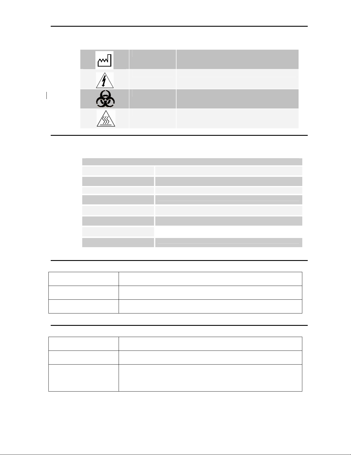
Symbols and Definitions (cont.)
Manufactured By Indicates Manufacturer of the Device
Electric Shock Indicates a potential risk of electrical shock
Biohazard Universal Precautions should be followed at all times
Hot Surface Use caution to avoid burn
Display Abbreviations
Display Abbreviations
PGM Program
Denat & Hyb Denaturation & Hybridization
Denat Temp Denaturation Temperature
Denat Time Denaturation Time
Hyb Temp Hybridization Temperature
Hyb Time Hybridization Time
Hyb Only Hybridization Only
Fixed Temp/Fxd Fixed Temperature
Audible Indicators - NORMAL
Single beep: All legal keystrokes.
Two quick beeps: Upon accepting a field and cursor has moved to next field.
Five beeps: Completion of process.
Audible Indicators – ERROR
Three short beeps: Entering of illegal or non-functioning keystrokes.
Low tone beep: Attempt to enter a value out of acceptable range.
Continuous beep: Instrument is not performing within acceptable range or program
condition. Turn off main power and restart. If beep continues,
discontinue use and contact service.

4
Error Messages
Instrument cannot achieve a set temperature by heating within 10 minutes an error message appears to inform user to
turn unit off and call service. A constant beep will sound.
If the instrument cannot measure the temperature, the software will automatically turn off the heating. An error message
will appear to inform the user to turn off the unit and call service. A constant beep will sound.
Instrument cannot achieve a set temperature by heating within 10 minutes an error message appears to inform user to
turn unit off and call service. A constant beep will sound.
High ambient temperature condition:
The instrument will attempt to achieve process set temperatures. However, if the cooling fan cannot achieve the
set temperature within 10 minutes, an error message will appear to inform the user that the ambient temperature is
high. A constant beep will sound. The counter will continue to count. The present temperature will be displayed.
Hitting the “Stop” button will allow the user to abort the process. A new screen will be displayed asking user if they
are sure they want to abort.
Please Wait
Cooling to XXX --°C
Present Temp: --°C
If the ambient temperature changes during a process and causes the instrument process set temperature to change
beyond the +/- 1°Cspecification for more than 2 minutes, a message will appear to inform the user that the
ambient temperature is high. A constant beep will sound. The counter will continue to count. The present
temperature will be displayed. Hitting the “Stop” button will allow user to abort the process. A new screen will be
displayed asking user if they are sure they want to abort.
If the ambient temperature changes after a process is completed, but before the user removes the slides and
causes the instrument process set temperature to change beyond the +/- 1°Cspecification for more than 2
minutes a message will appear to inform the user that the ambient temperature is high. A constant beep will sound.
The counter will continue to count. The present temperature will be displayed. Hitting the “Stop” button will allow
user to abort the process. A new screen will be displayed asking user if they are sure they want to abort.
Note: If 40 programs have been created or edited the software will blank out the “Create” mode on the main menu
screen. This will only allow users to edit existing programs.
SYSTEM ERROR!
TURN UNIT OFF!
CALL SERVICE
Please Wait
Cooling to XXX --°C
Ambient Temp High!
PGM -- namexxxxxx
“Ambient Temp High!”
Hyb --°C --:--
Present Temp: --°C
PGM -- namexxxxxx
“Ambient Temp High!”
Reset Timer 00:00:00
End PGM/Main Menu
PGM -- namexxxxxx
“Ambient Temp High!”
Total Hyb Time --:--
End PGM/Main Menu
Run a PGM
Edit a PGM
Present Temp: --°C
5
Section 3
Operating Instructions
Opening and Closing the Lid
The platen may be hot. Use caution and check temperature on display before handling slides. Improper
precaution can cause a burn.
Depressions located on either side of the lid allow user to simply lift lid into position. The lid should offer
some resistance when opening. To close, reverse process. Assure front is completely down and no
obstructions prevent gasket seal from sealing on housing base.
Turning Unit On
The ThermoBrite main power switch is located on the rear panel. Assure unit is plugged into a grounded
outlet. Move switch to on position. Instrument will beep to announce power has been turned on, fan will
start and the Main Menu will come up onto the display.
I = ON O=OFF
Run a Denaturation and Hybridization Program
Turn unit on and wait for the Main Menu screen. Cursor highlights “Run a PGM” line.
Press “Enter” button to accept.
With the arrow keys scroll through program numbers 1 to 40 / program names. If no programs have been
saved advance to programming section of this handbook. To accept, press “Enter” button.
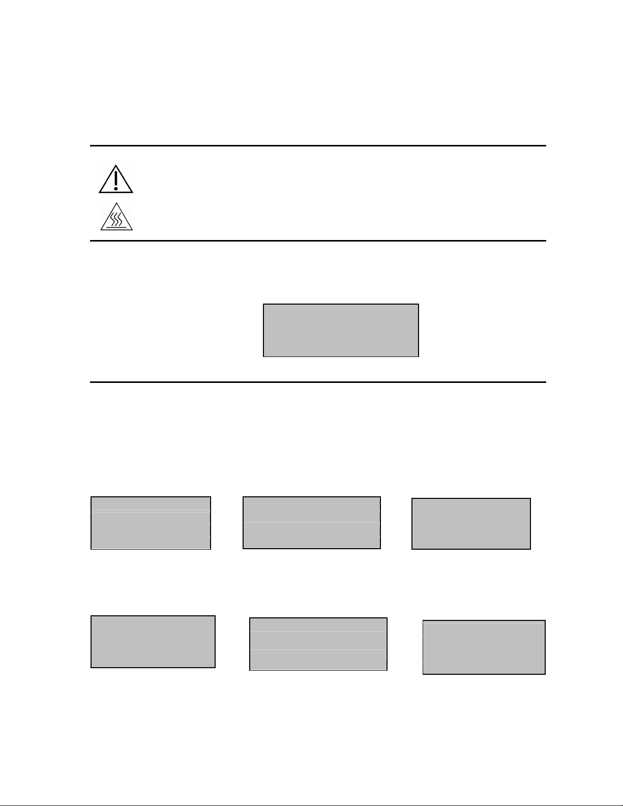
Display will confirm PGM number/name and Denat & Hyb times and temperatures. Cursor highlights “Run
PGM” line. Press “Enter” button to accept.
Hyb Only Denat & Hyb Fxd Temp
PGM 01 Her2
82°C :05; 45°C 16:00
Run PGM
Main Menu
The display prompts to “Add Slides and Close Lid”. Before adding slides, insert two Humidity Cards into the
inside lid. After card insertion saturate with distilled water or equivalent (see Humidity Control Cards).
Cursor highlights “Start” line. Press “Enter” button to run the program.
(To return to the Main Menu, move the cursor to highlight “Main Menu” line and press “Enter” button).
Run a PGM
Edit a PGM
Create a PGM
Present Temp: 37°C
PGM 02 EBV
Hyb: 55°C 01:30
Run PGM
Main Menu
PGM 03 Appl
Fixed: 65°C
Run PGM
Main Menu
PGM 03 Appl
Add Slides - Close Lid
Start
Main Menu
PGM 02 EBV
Add Slides - Close Lid
Start
Main Menu
PGM 01 Her2
Add Slides - Close Lid
Start
Main Menu

6
Denaturation and Hybridization:
Display indicates present temperature of the slides. Once temperature reaches denaturation set point, ThermoBrite will beep
twice and denaturation time will count down from the set time.
PGM 01 Her2
Denat in Process
Denat: 82°C 02:28
Present Temp: 82°C
The ThermoBritewill automatically cool to hybridization set temperature once denaturation is completed.
Please Wait
Cooling to Hyb 45°C
Present Temp: 58°C
Hybridization time will count down from the set time once temperature reaches hybridization set point.
Upon program completion ThermoBrite will beep five times and the display will show “PROCESS COMPLETE”. Hybridization
temperature will be maintained until “End PGM/Main Menu” is accepted by pressing “Enter” button. Before pressing
“Enter” button, remove slides for further processing. If “End PGM/Main Menu” is not accepted within the first minute of
program completion, hybridization time will start counting the total time at hybridization temperature.
PGM 01 Her2
PROCESS COMPLETE
Total Hyb Time 21:05
End PGM/Main Menu
Hybridization Only:
Upon program completion ThermoBrite will beep five times and the display will show “PROCESS COMPLETE”.
Hybridization temperature will be maintained until “End PGM/Main Menu” is accepted by pressing “Enter” button. Before
pressing “Enter” button, remove slides for further processing. If “End PGM/Main Menu” is not accepted within the first
minute of program completion, hybridization time will start counting the total time at hybridization temperature.
Fixed Temperature:
Display indicates present temperature of slides.
Please Wait
Heating to Fxd: 65°C
Present Temp: 30°C
Turn unit on and wait for the Main Menu screen. Cursor highlights “Run a PGM” line.
Timer counts elapsed time. (Pressing “Enter” button will reset timer to zero).
PGM 02 EBV
PROCESS COMPLETE
Total Hyb Time 02:15
End PGM/Main Menu

7
PGM 03 Appl
Fixed Temp: 65°C
Reset Timer 01:18:10
End PGM/Main Menu
Use Arrow keys to move to “End PGM/Main Menu” line and press “Enter” button to accept.
Note: If ambient temperature is programmed the fan will continually cycle until the program is
aborted.
Note: The temperature can be increased or decreased as the unit is running by using the up/down
arrows from the “Fixed Temp” line.
Abort Program in Process
To end a program in process press “STOP” button, three beeps will sound. Use arrows to move cursor to
“Yes” line and press “Enter” button to accept. (Program will continue to run until “Yes” or “No” has been
accepted)
Note: The ThermoBrite prompts, “Are You Sure?” This measure is to prevent accidental disruption of a
program in process.
ABORTING!!
Are You Sure?
No
Yes - Main Menu
Fan will turn on. If the slide temperature is above 37ºC, the fan will cool to 37ºC.
Slide Installation
When prompted simply lift lid and load slides onto plate. Frosted edge of the slide should hang over
edge. Move slide toward middle of plate butting edge into marked positions in slide locator.
Be sure slides rest into slide locator before closing lid. For optimum temperature uniformity, use
blank slides to fill all unused spaces before closing lid. This will allow maximum performance of the
ThermoBrite.
Humidity Control Cards
To replace cards, lift lid and remove. Slide card into slot positions, allow tabs in lid to support cards.
Do Not use paper towels or any other filter card in card positions, this may change the humidity and may
decrease the intensity of the probe, causing potential false negative results.
Predefined Limits
Program Mode Temperature Range Timer Limits
Denature 50ºC to 99ºC 0-30 minutes
Hybridization Room temp: 30ºC to 70ºC 0-99 hours
Fixed Temp Room temp: 30ºC to 99ºC 0-99 hours

8
Section 4
Specifications
Table
Product No. TS01 TS02
Model No. S500-12 S500-24
Capacity Up to 12 slides
Processing Time 0-100 hours
Number of Programs 40
Ramp Time 37 – 95ºC in less than 3 minutes
Cooling Time 95 - 45ºC in less than 6 minutes
Electrical 120 VAC @ 3.0 A 240 VAC @ 1.6A
Dimensions Depth 45.1 cm
Width 22.8 cm
Height 14.6 cm
Weight 8.5 kg
Environmental Indoor use
Altitude up to 2000m
Temperature 15ºC to 40ºC
Maximum relative humidity 80% for temperatures up to 15ºC decreasing
linearly to 50% relative humidity at 40ºC
Main supply voltage fluctuations not to exceed +/- 10% of the nominal
voltage
Transient over-voltages according to installation category II
Pollution degree 2
Specifications are subject to change without notice and at any time.

9
Section 5
Theory of Operation
Overview
The ThermoBrite is a programmable device that is used to control a plate upon which samples are placed to
precision temperatures. The device is required to move quickly between various set temperatures with little or no
overshoot and then remain at the set temperature within +-1 degree for any desired time. Heat is added to the
system by means of a resistive heating pad bonded to the plate and removed by controlling ambient air flow
through the device and under the plate. Plate temperatures are measured via an RTD embedded between the
heating pad and plate. The RTD is connected to analog circuitry which signal conditions the RTD resistance to
provide a voltage between 0 and 5 volts to a 12 bit analog to digital converter (ADC). The input voltages are scaled
for RTD temperatures of between 15 and 105 degrees C. A microprocessor based system acquires temperature
data via this ADC, conditions it with calibration data and uses the result to run a proportional, integral, derivative
(PID) control algorithm to meet temperature requirements. The rest of this document will describe the temperature
data acquisition, calibration data signal conditioning, and PID control processes in detail.
Data Acquisition
The system microprocessor, using an integrated timer starts and reads conversions from the 12 bit ADC every 2
mSecs. To provide some noise immunity the ADC interrupt handler sums 8 consecutive readings in an
accumulator. After the 8th reading the accumulator value is loaded into a globally accessible 16 bit integer for use
by other routines. This accumulator is also written to a 16 value array. The newest entry in the array minus the
oldest is also provided in a globally accessible 16 bit integer. This provides temperature rate information to other
routines (i.e. the change in ADC value over 256 mSecs), When the PID algorithm runs (see below) this raw ADC
data is converted to temperature and rate of change of temperature data via calibration data (see below)..
Calibration
An RTD changes in resistance with changing temperature with a roughly linear characteristic. This response is not
perfectly linear however and so to reduce temperature measurement errors and to account for initial tolerances in
the analog signal conditioning circuitry and the RTD itself, a calibration routine is provided. The calibration provides
for measured temperatures to be matched with ADC readings at 5 points along the temperature range of interest.
By having known temperatures at fixed points on the ADC curve the measured temperature can be calculated with
a linear interpolation between these points. This allows the RTD characteristic to be broken up into 4 shorter
segments so that the RTD transfer function can be modeled with a linear approximation over that short span without
introducing significant error. The calibration is done via the microprocessor serial port. The device is instructed to
control the temperature to various points along the usable range from low to high(i.e. 25, 35 ,55 ,75, and 95 C).
When the temperature stabilizes at each point the value of the actual temperature (as measured by an accurate
independent device) is input and the microprocessor also records the ADC reading and saves both values. After
completing all 5 points the microprocessor calculates the gain between points in degrees C/ADC count (i.e. gain[n-
1] = (Temp[n]-Temp[n-1])/(ADC[n]-ADC[n-1])). In normal operation the microprocessor uses this calibration data in
the following manner: For any given ADC value the microprocessor searches the list of calibration data to find the
point that has ADC value less than or equal to the measured value and for which the next higher point has ADC
value greater than the measured value. We will call these points m and m+1 where m is 0 to 3. The temperature is
then calculated as Temperature = ( Temp[m] + gain[m]*(ADC-ADC[m]) ). If the ADC value is lower than the lowest
cal point then the data from cal point 0 is used. If the ADC value is above the highest cal point (4) then the gain
between points 3 and 4 is used. The temperature rate information is calculated from the ADC rate information by
just multiplying by the gain currently used.

10
PID
The system uses a PID algorithm to get quick and precise control of temperatures over the usable range of the instrument. If
we define a temperature error (E) as the difference between the temperature setpoint and the measured temperature, a
standard PID control would involve the following equation:
Control = Pg*E + Ig*∫E *dt+Rg*dT/dt
Where: Pg is a constant (proportional gain)
Ig is a constant (integral gain)
∫E *dt is the integral of the error term E
Rg is a constant (rate gain) (typically negative)
dT/dt is the temperature rate of change in deg C/sec
Control is an analog value describing the amount of heat to put into or take out (if
negative) from the system
Since this device only has a microprocessor and not a Cray we approximate some of these values. As described above the
temperature rate of change is approximated by storing a rotating buffer of ADC values so that the change of ADC over
periods of 256 mSecs can be calculated. The integral value is approximated by summing the error, E, at a constant time
interval to an accumulator (i.e ΣE). . Additionally since we do not have an analog control that can adjust a continuous supply
of heat into the system we approximate that by converting the control output to a duty cycle of a control period. So for
example, as the temperature approaches the set temperature and the control value becomes small, the heat is applied for a
brief fraction of the control period. When the temperature is away from the set temperature the heat is applied for most or all
of the control period. Naturally the amount of heat that can be applied over a control period is capped at whatever the heating
element can provide full on. A negative output out of the PID means that cooling is required and this controls the fan in a
similar manner as the heater. The nominal cycle time for the heater is 500 mSecs and 1000 mSec for the fan. The PID
output gives a fraction of these values and as described above is capped at 100%.
The purpose of the terms in the PID is straightforward. The proportional term gives an output that tries to drive the control to
reduce the temperature error. So, for instance, as long as the temperature is below the set temperature, the proportional term
will ask for heat according to:
Control = Pg*E
Of course the problem with this is that if you reach the set temperature, the error E is 0 and the Control would no longer be
asking for heat. If there is any heat flow out of the system (to ambient surroundings) as there most certainly is, then the
proportional term is incapable of maintaining a zero error and will be stable at some value of E were heat into the system
matches that lost to the outside. Introduction of the integral term is thus required. Now as long as a nonzero error E exists,
the integrator value continues to grow, which causes the Control value to increase until enough heat is supplied to the system
to drive the temperature to the set temperature. If the temperature matches the set temperature the integrator ceases to
change since E is now zero. Thus the integrator can hold a value that keeps the Control supplying heat to match loses to the
surroundings:
Control = Pg*E + Pi*ΣE or when E=0 Control = Pi*ΣE
Unfortunately this configuration is inherently unstable. When the temperature is below the set temperature, the integrator will
grow of course in a direction to drive the temperature up. The integrator will always grow to a value that is greater than that
needed to stay at the set temperature. The only way that the integrator can reduce in value is for the temperature to cross
above the set temperature so that E becomes negative. In order that the temperature can be driven back down to the set
temperature the integrator will need to reduce to a value less than that required to hold the temperature constant and so the
temperature will drive cooler than the set temperature until the integrator can grow again. The result then is a temperature
that oscillates around the set temperature.
To eliminate this instability the rate term is added. As stated above, the rate gain constant is negative so that the effect of the
term is to produce a Control value that resists rate of change of temperature. So for example an increasing temperature
produces a negative rate term which tends to reduce the size of the positive Control value. This term then by resisting
changes in temperature reduces the amount of energy that is added to or removed from the system when the temperature is
below or above the set temperature (with the integrator changing accordingly) and the integrator cannot maintain a stable
oscillation around the set temperature. Now the stable condition (if the control constants are properly selected and the
system properties allow stability) is a steady temperature at the set temperature where E=0, the integrator holds the value
necessary to supply the amount of heat via the Control to match heat loss to the surroundings and since the temperature is
unchanging, has no rate term contribution.

11
Section 6
Alignment
Materials
IBM compatible computer w/min P3 1Ghz, 9pin serial port and Hyper Terminal software installed.
Standard 9-pin male to 9-pin female serial printer cable.
Hi-Pot tester, equipment
Cole-Parmer thermometer
RS232 adapter, equipment
Data Logger, equipment
Six Temperature Probes
Workstation Setup
Boot-up the workstation and go to Start/Programs/Accessories/Communication and select “Hyper Terminal”.
Perform the following in the Hyper Terminals’ main screen:
Select File/Properties and configure the port settings to:
9600 Bits per second
Data Bits is set to (8)
Parity is set to none
Stop Bits is set to (1)
Flow Control is none.
Procedure
Setting up the ThermoBrite to workstation
Note: If any of the following tests fail to perform correctly then test or tests will be repeated.
Unplug unit from outlet and turn on its side to expose bottom surface.
Locate and remove access panel.
Attach the RS-232’s adapter cable to J3 of the unit being tested.
Attach one end of the serial cable to the RS-232 adapter and the other end to the serial port on the
workstation.
Turn on the ThermoBrite unit and the message “Hello World” should appear on the computer screen.
Select “H” to access the help screen.
Note: This screen will provide a list of options.
Select “S” for sign on and choose either Dako for Hybridizer or StatSpin for ThermoBrite.
Select “L” to cycle through the languages and select the “English” version.
Press the “Esc” key.
Select “9” for the PID. Confirm the following items in Setup:
1) Prop gain: 30.0
2) Rate gain: 120.0
3) Int gain: 0.04
4) Heating int deadband: 2.0
5) Cooling int deadband: 4.0

12
6) Heating rate deadband: 15.0
7) Cooling rate deadband: 1.0
8) Intergrator max value: 1000.0
9) Heating cycle time 500 ms
A) Cooling cycle time 1000 ms
B) Duty cycle deadband 0.30
X) Ambient cycle time 2000 ms
Y) Ambient duty fraction 0.05
Z) Use offset: Yes
C) Setpoint: XX.X C
D) Defaults
S) Save new coefficients to NVRAM
Q) Quit
Select “Z” and turn off the Offset.
Select “S” to save to NVRAM.
Select “Q” to quit.
Select “P” for Program.
Select “E” to erase all programs.
Select “Y”.
Calibration
Power up Data Logger or Thermometer and insert one Temp probe w/slide into position 5 or 6 on the
ThermoBrite unit.
Close the cover and apply a ten-pound weight to the cover.
Note: The ten-pound weight is used to keep the glass slide with the temp probe attached, flat
against the heating plate.
Select “C” for Calibrate.
Read the temperature value on the Data Logger and input this value. Press the “Enter” key.
Select as Cal pt 0 (Calibration Point Zero).
Select “C” for Calibrate.
Enter 30.0°C and press the “Enter” key for a new set point.
Note: The unit will now start to heat up to 30.0°C. You should see the temperature
measurement from the unit “RTD” and Data Logger start to rise.
Once the RTD temp and Data Logger temperatures are stable, enter the data Logger temp into the computer
and select Cal pt 1.
Select “C” for Calibrate and enter 35.0°C. Press the “Enter” key for a new set point. Once the RTD and Data
Logger temperatures are stable, enter the Data logger’s value into the computer and select Cal pt 1.
Note: The value for the Data Logger should be exactly 35.0°C. If not then repeat this step.
Select “C” for Calibrate and enter 50.0°C. Press the “Enter” key for a new set point. Once the RTD and Data
Logger temperatures are stable, enter the Data logger’s value into the computer and select Cal pt 2.
Select “C” for Calibrate and enter 55.0°C. Press the “Enter” key for a new set point. Once the RTD and Data
Logger temperatures are stable, enter the Data logger’s value into the computer and select Cal pt 2.
Note: The value for the Data Logger should be exactly 55.0°C. If not then repeat this step.
Select “C” for Calibrate and enter 70.0°C. Press the “Enter” key for a new set point. Once the RTD and Data
Logger temperatures are stable, enter the Data logger’s value into the computer and select Cal pt 3.
Select “C” for Calibrate and enter 75.0°C. Press the “Enter” key for a new set point. Once the RTD and Data
Logger temperatures are stable, enter the Data logger’s value into the computer and select Cal pt 3.
Note: The value for the Data Logger should be exactly 75.0°C. If not then repeat this step.

13
Select “C” for Calibrate and enter 90.0°C. Press the “Enter” key for a new set point. Once the RTD and Data
Logger temperatures are stable, enter the Data logger’s value into the computer and select Cal pt 4.
Select “C” for Calibrate and enter 95.0°C. Press the “Enter” key for a new set point once the RTD and Data
Logger temperatures are stable, enter the Data logger’s value into the computer and select Cal pt 4.
Note: The value for the Data Logger should be exactly 95.0°C. If not then repeat this step.
Select “S” for Save. The alignment is complete.
Select “H” for the Help menu.
Select “9” for PID.
Select “Z” and turn on the Offset.
Select “S” to save to NVRAM.
Select “Q” to Quit.
Testing
Start a ThermoBrite test record by recording the Start Date, Serial #, and Instrument voltage.
Install the 6 temp probes w/slides onto the heater plate as per the layout on the ThermoBrite test record.
Close the cover and apply a ten-pound weight to the top of the cover.
Turn on the Data Logger.
Insure that the proper line cord is used (120v or 240v) and record the results on the test record.
Note: The voltage will be listed on the device serial number label.
Turn on the ThermoBrite unit.
The Name “DakoCytomation” (Hybridizer) or “StatSpin Inc.” (ThermoBrite) and the software revision will
appear on the display for a short time.
Note: The prompt screen will supersede this screen.
Record the software revision and “Boot” results on the test record.
Use the arrow keys to move the curser on the display and choose EDIT a program. Press the “Enter” key.
Choose program #1 and press the “Enter” key.
Choose FIXED for the type of program. Enter FIXED in the “Mode” section on the test record.
Type 0123456789 in the name field and record the results on the test record Beep and Keypad section.
Note: Each time the keypad is depressed a beep is sounded and all characters are displayed in
the display window.
Set temperature to 45.0°C and press the “Enter” key.
Choose run program and press the “Enter” key.
Choose program #1.
Note: The unit will heat to 45.0°C and then beep.
Start the timer on the unit being tested.
Note: The display in the unit will start to count up in seconds.
Check with a stopwatch for 30 seconds that the timer on the unit is correct.
Record the temperature readings at 2, 5, and 10-minute time intervals for the six probes.
Note: The 45.0°C test readings should be between 44.0°C and 46.0°C. The unit passes the test
if the readings are within range.
End the test by depressing the stop button.
Note: The fan should come an as the unit cools down. If the fan is running then check off the
Fan as passed on the test record.
Power off the unit after the it has cooled down to 37.0°C.
Turn the unit on and select “Edit” a program.
Note: The temperature will be set to 95.0°C.
Record the time it takes to get from 37.0°C to 95.0°C on the test record when the program starts to run.

14
Note: It will beep once it reaches 95.0°C.
Start the timer and record the temperature readings at 2, 5, and 10-minute intervals for the six probes.
Note: The 95.0°C test readings should be between 94.0°C and 96.0°C. The unit passes the test
if the readings are within range.
Depressing the Stop button and end the test.
Record the time it takes to cool down from 95.0°C to 45.0°C.
Watch the display to see if it remains legible (not to dim) during the cool down. Record the results within the
Display section of the test record.
Use a DC hi-pot tester and perform the Line Dielectric Voltage withstand/Grounding continuity Test. Record
the results on the test record.
Inspect assembly for blemishes record the results in Cosmetic section of the test record.
Verify that the UL, CE, Hot, and serial # labels are installed.
15
Section 7
Programming
Overview
ThermoBrite is capable of storing 40 different programs. Each program can be one of three program
types:
oDenaturation and Hybridization (Denat & Hyb),
oHybridization Only (Hyb Only) or
oFixed Temperature (Fixed Temp).
Select PGM Type
Denat & Hyb
Hyb Only
Fixed Temp
Programming is simple. Select program type, and follow screen prompts to enter run times and set
temperatures. ThermoBrite maintains set temperatures for duration of the processing.
Note: At end of program the display will show “Process Complete”. Temperature will be maintained and timer
will continue to run until End PGM/Main Menu is accepted by pressing “Enter” button.
Note: If all 40 program numbers have been used ”Create a PGM” line in the Main Menu will no longer appear.
An existing program must be edited, see “Editing a Program”.
Character Selection
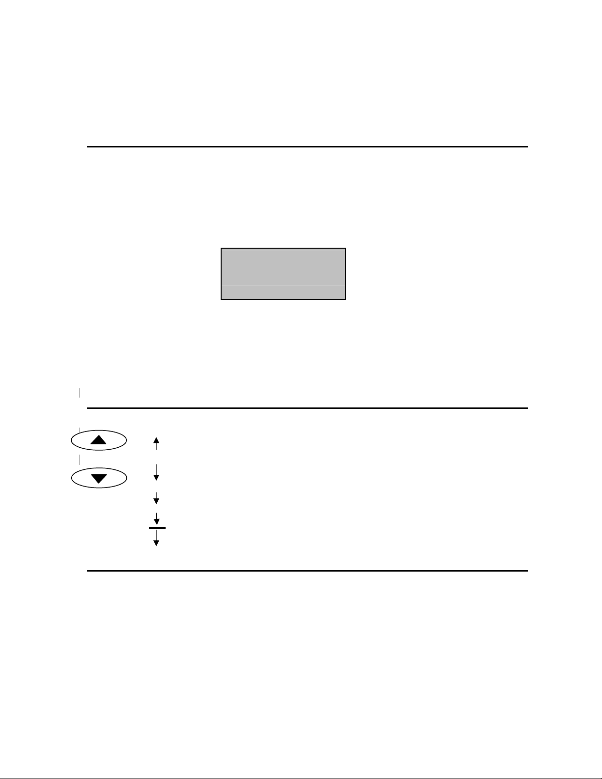
•ThermoBrite allows creating a program name. Cursor highlights the first name
character position.
•Use the arrow keys to move through character set and press “Enter” button to
accept the characters.
•All 10 character positions must be used and blank spaces are acceptable. Press
“Enter” button to accept blank characters.
•For numeric characters use keypad 0-9.
Creating a Denaturation and Hybridization Program (Denat & Hyb)
From the Main Screen, use the arrow keys to move cursor to “Create a PGM” and press “Enter” button to
accept.
Cursor highlights “Denat & Hyb” line; press “Enter” button to accept.
ThermoBrite will advance to the next available program number.
For specific programming instruction refer to units operators manual.
Z
A
“Blank”
•
Z
This manual suits for next models
3
Table of contents
Popular Laboratory Equipment manuals by other brands


Macherey-Nagel
Macherey-Nagel NANOCOLOR TIC-Ex manual

IKA
IKA IKA C 248 operating instructions

WONDFO
WONDFO Finecare FIA Meter Plus Operation manual

Thermo Scientific
Thermo Scientific 2032 Operating and maintenance manual

BC Northern Lights
BC Northern Lights Producer Technical manual

Thermo Scientific
Thermo Scientific NanoDrop One user guide

Leica
Leica CM3600 XP Instructions for use

NEW BRUNSWICK SCIENTIFIC
NEW BRUNSWICK SCIENTIFIC C-24 Guide to operations

Cell Guidance Systems
Cell Guidance Systems Exo-spin Mini-Columns user guide

Labnet
Labnet S0200 user manual

ELGA
ELGA PURELAB 7000 - US Quick start manual

BioChain
BioChain AnaPrep 12 Dx instruction manual