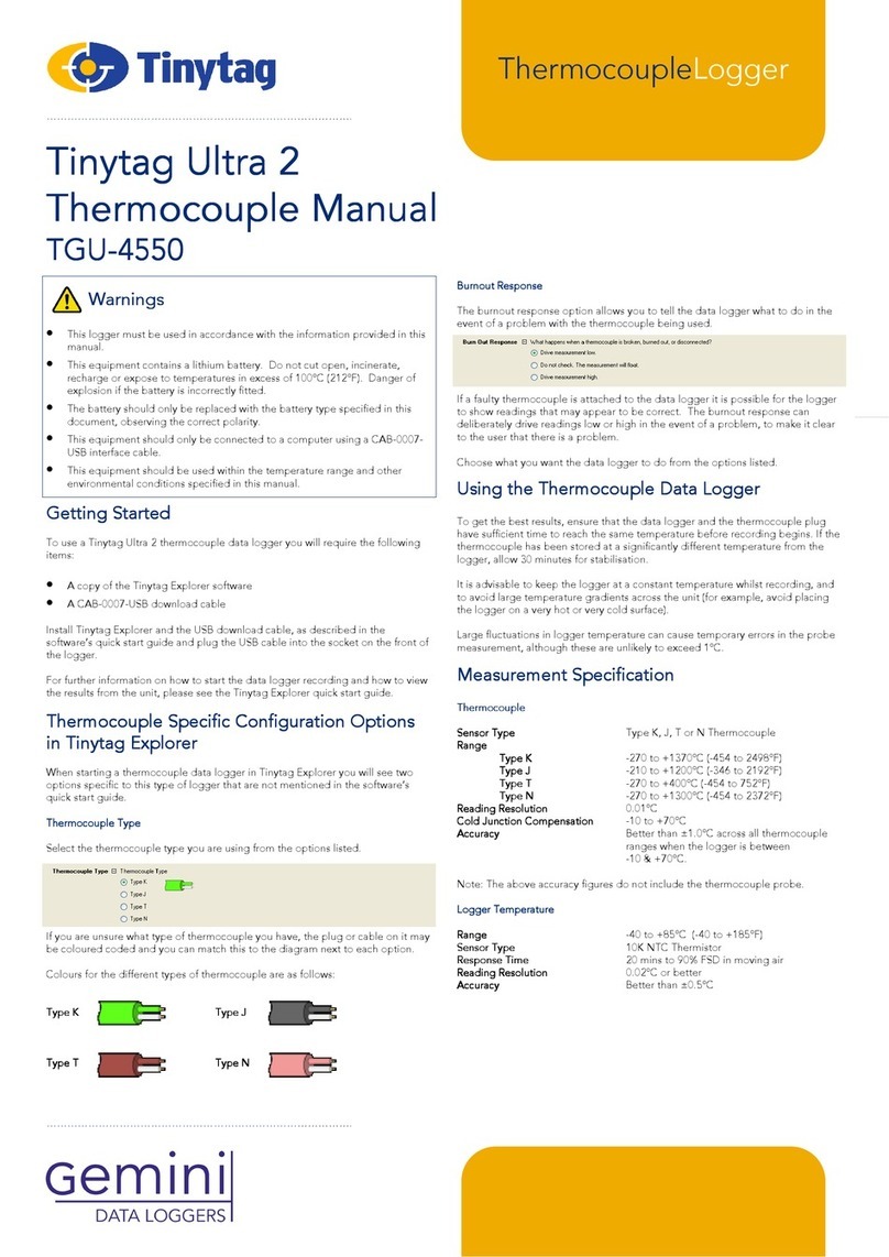
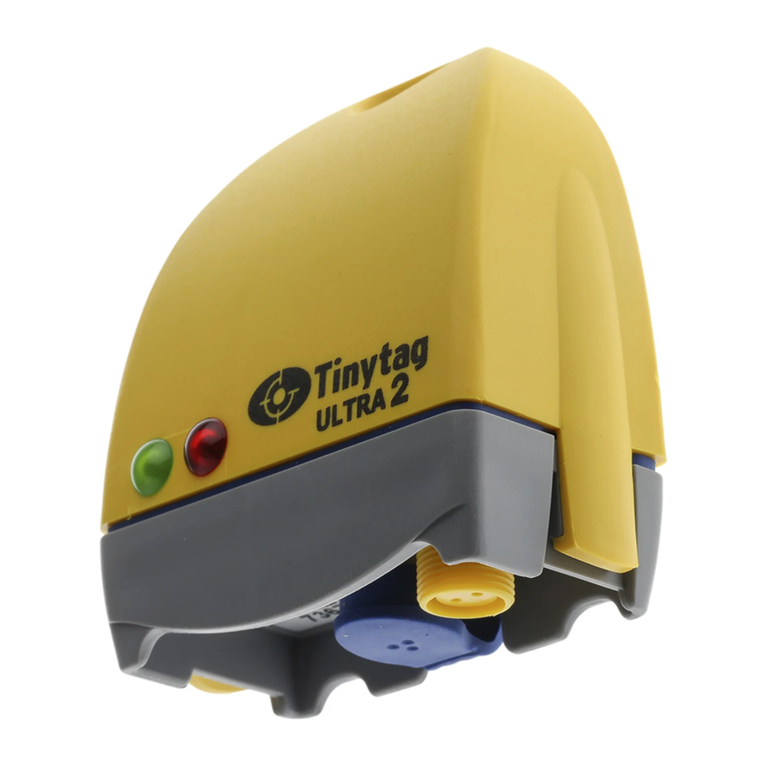
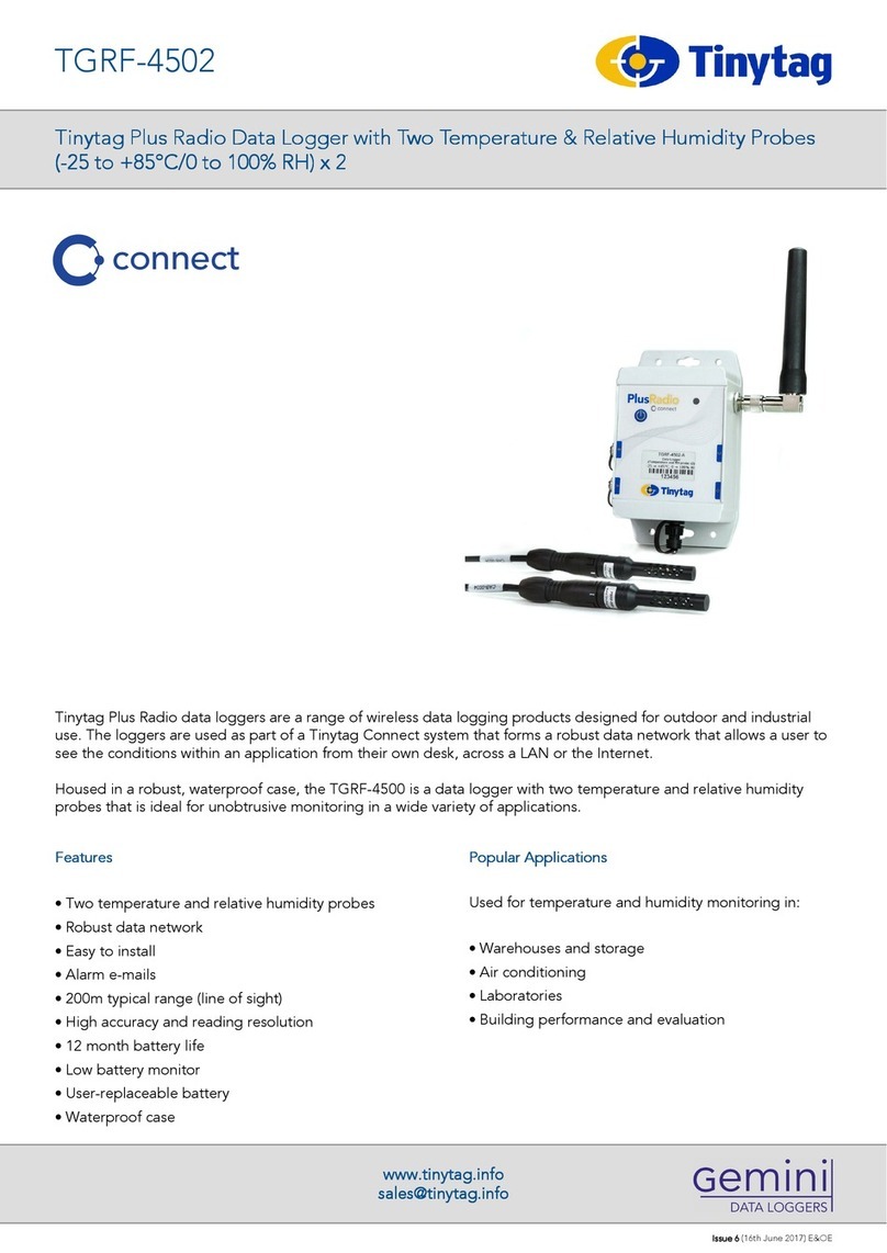
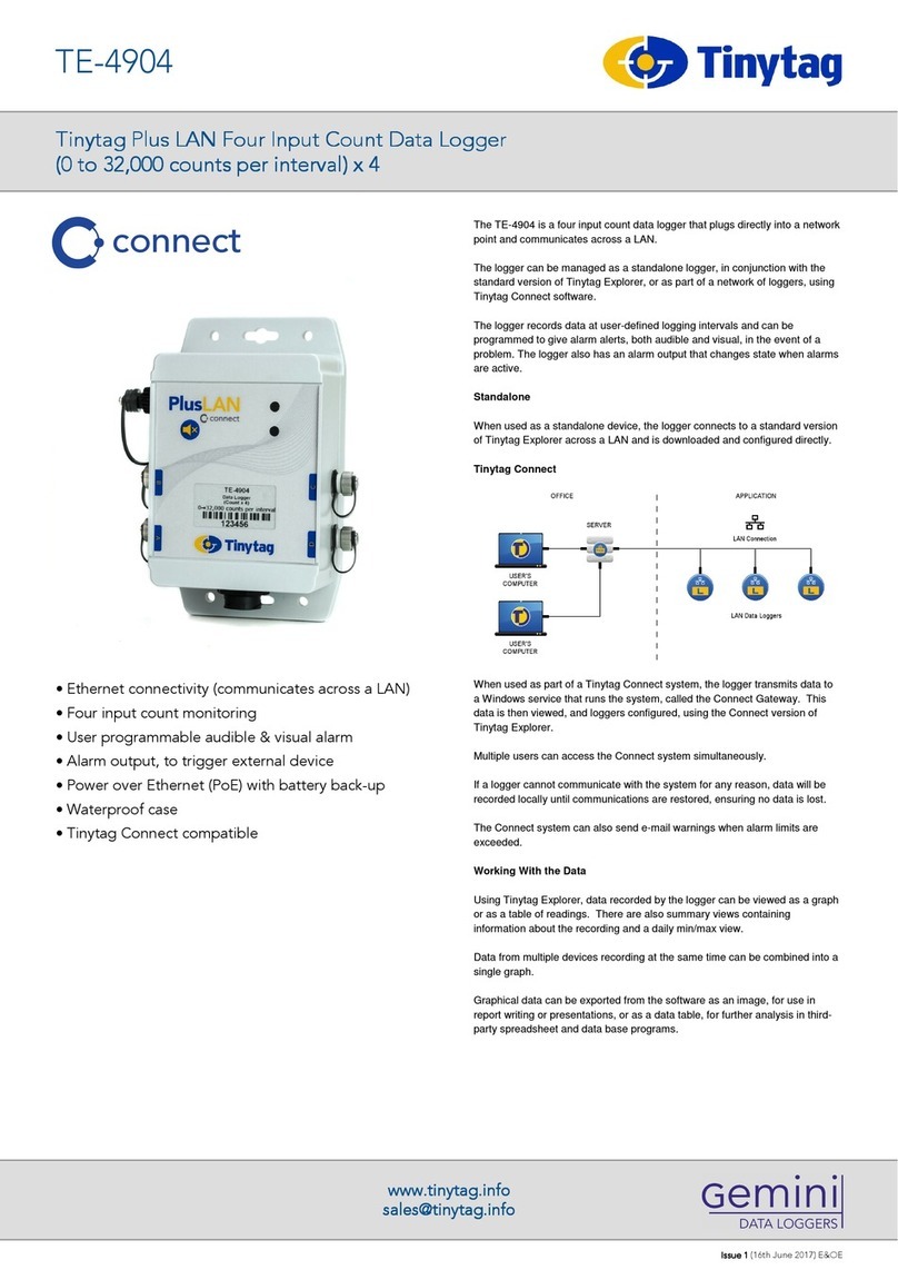
Tinytag TGRF-4021 User manual

Tinytag connect
User Manual
Tinytag Explorer Connect Software Included


Contents
Introduction 2
Getting Started
1.1 What You Need 4
1.2 Software Installation & Setup 5
1.3 USB Receiver Hardware Installation 7
1.4 Ethernet Receiver/LAN Logger Hardware Setup 8
1.5 Ethernet Receiver/LAN Logger Software Setup 9
1.6 Tinytag Connect Gateway Software Setup 12
1.7 Connecting to a System from Another Computer 15
1.8 Enabling the Tinytag Connect Navigation Pane 16
1.9 Radio Logger Setup 17
1.10 Using a Tinytag Connect Device 18
1.11 Logger Icons 19
System Information
2.1 System Components 22
2.2 System Overview 23
2.3 Gateway Configurations 27
2.4 Data Logging 30
2.5 Data Transmission 31
2.6 Alarm E-Mails 32
2.7 Exporting Data 33
2.8 Modbus 36
2.9 Power 39
2.10 Troubleshooting 42
Radio
3.1 Radio Specification 44
3.2 Positioning & Mounting Instructions 45
3.3 Installation 47
3.4 System Configurations 49
3.5 Receiver Configurations 51
3.6 Mesh Network Behaviour 53
3.7 Radio Configuration 57
3.8 LED Flash Patterns 60
Ethernet/LAN
4.1 Mounting Instructions 62
4.2 Alarms 63
4.3 LED Flash Patterns 65
Appendix
a System Requirements 66
b Software Licence 67
c Regulatory Compliance 67
d Approvals 67
e Further Information 67

Introduction
This guide explains how to set up and run a Tinytag Connect system.
It covers the installation of a system, an overview of how it works and then specific information
on the different types of logger the system supports (radio and LAN connected products).
All users are advised to run the latest version of the Tinytag Explorer software. The latest
version of the software can be downloaded from:
www.tinytag.info/support
2
INTRODUCTION

Getting Started

4
1.1 WHAT YOU NEED
1.1 What you need
To use a Tinytag Connect system you will require the following:
• A copy of the Tinytag Explorer Connect software CD
• A Tinytag Connect activation code (this can be found inside the front cover of this manual)
• A Tinytag Connect device (Radio receiver, loggers and/or LAN logger)
• Associated probes and cables
• Associated power supplies (if required)
You will also need a computer to run the system; it is recommended that the software be run
on a server if possible.
For further information on system configurations, please see the System Information
section of this document.

51.2 SOFTWARE INSTALLATION & SETUP
1.2 Software Installation & Setup
For information on system Requirements refer to the Appendix.
Warning! To install Tinytag Explorer, you will need to have Windows Administrator
Access rights on the server or computer you are using.
• Place the Tinytag Explorer CD into the CD drive of your PC. The Tinytag Explorer Installer
will run automatically after a few seconds and present you with a Welcome screen. If
Tinytag Explorer Installer does not run automatically, open Windows Explorer, navigate to
your CD drive and double-click tinytag.msi.
• Click Next to start the installation.
• Review the software’s licence agreement and if you accept the terms click I accept the
terms in the Licence Agreement, then Next.
• You will then be asked where you want to install the software (we recommend you use
the default installation path) and whether you would like a shortcut for the software to be
created on your desktop. Once you have made your choices, click Next, then Install.
• The software will then install automatically (you may be prompted by Windows to confirm
your agreement to the installation). When you see the Installation Complete screen, click
Finish.
• Once the installation is complete, you will be asked to restart your computer. Click Yes to
do this.
Starting Tinytag Explorer Connect
To start Tinytag Explorer, click on the desktop icon for the software:

6
1.2 SOFTWARE INSTALLATION & SETUP
If you didn’t create a desktop icon when installing the software, you can start the
software by going to:
Start >> All Programs >> Tinytag Explorer >> Tinytag Explorer
Activating Tinytag Explorer Connect
The first time you run Tinytag Explorer you will be prompted to activate the software.
Enter the activation code into the box provided and choose whether you want it to be
applied to all the user accounts on the computer.
Next click Confirm Code and you will see a message to confirm that the code has been
accepted.
The activation code for Tinytag Explorer can be found on the inside front cover of
this manual. It is a set of 20 characters split up into 5 blocks of 4. If you have lost or
misplaced your activation code, please contact your supplier
You may need Windows Administrator access rights to activate the software for all user
accounts. If you do not have Administrator access rights, leave the box unchecked and
the software will only be enabled for the current user account.

71.3 USB RECEIVER HARDWARE INSTALLATION
1.3 USB Receiver Hardware Installation
Plug the USB cable supplied with the receiver into a USB port on your computer.
Depending on the version of Windows you are using, you should see a message to say that
Windows has detected and is installing a new device.
When the installation is complete, plug the cable into the receiver and turn the receiver on.
The receiver should then be located so that it is within range of one or more data loggers (an
elevated position may help).
Now go to Section 1.6: Tinytag Connect Gateway Software Setup

8
1.4 ETHERNET RECEIVER/LAN LOGGER HARDWARE SETUP
1.4 Ethernet Receiver/LAN Logger Hardware Setup
Ethernet receivers and LAN loggers are Power over Ethernet (PoE) devices. If a PoE plug-in
injector is supplied, the device should be connected up using Ethernet cables (not supplied)
as shown below:
Once connected, turn the device on.
Locate and make a note of the MAC address on the back of the device being installed, this
will be needed later.
If the device is being used in a location where moisture or dust is present, the supplied
waterproof RJ45 shroud should be fitted over the Ethernet connection.
To fit this, thread the Ethernet cable through the shroud, plug the cable into the device and
then screw the shroud into the device.

91.5 ETHERNET RECEIVER/LAN LOGGER SOFTWARE SETUP
1.5 Ethernet Receiver/LAN Logger Software Setup
To install a Tinytag Plus Radio Ethernet Receiver or LAN Logger:
On the computer that will run the Master Gateway, install and activate the Tinytag Explorer
Connect software, as previously described.
Browse the Tinytag Explorer CD and locate the LAN folder
Run the program VirtualCommPort.exe and follow the instructions in the onscreen prompts
Run the program IPsetup.exe. Devices are listed by their MAC address in the Select a Unit
section.
Highlight the required device and click on the Launch Webpage button.
Make a note of the IP address of the device (from the URL of the web page).
Make a note of the Listening network port number for PORT 0.

10
1.5 ETHERNET RECEIVER/LAN LOGGER SOFTWARE SETUP
Set Select serial port to COM100 (if installing
more than one device, increment the port
number for each successive device used).
Run the Virtual Comm Port software (this is called NB Virtual Comm Port and can be found
on the Windows Start Menu under NetBurner NNDK) and click Add.

11 1.5 ETHERNET RECEIVER/LAN LOGGER SOFTWARE SETUP
In the Remote host name/port fields type the IP address of the Ethernet device and the
Listening network port number (as previously determined) and click Add and Apply. The
device is now ready to use.

12
1.6 TINYTAG CONNECT GATEWAY SOFTWARE SETUP
1.6 Tinytag Connect Gateway Software Setup
Configuring a Master Gateway
With the receiver or logger plugged into the computer or network, start Tinytag Explorer
and go to Options and Communication Options.
Next, click on the Tinytag Connect tab and select Use a Tinytag Connect Product, then
select Direct connection to Tinytag Connect Device and click on the Configure Gateway
button.
Select Master Gateway, then Next

13 1.6 TINYTAG CONNECT GATEWAY SOFTWARE SETUP
Serial Port Set Up
Choose the Use fully automatic serial port detection option (recommended) or, if using
LAN loggers, select the serial ports configured previously from those listed in the Manual
selection section and click Next.
E-Mail Alarm Notifications
Tinytag Explorer can be set to send e-mail alerts when user defined logger alarm limits are
exceeded (the user account that the system is working on must have a properly configured
e-mail account for this to work).
To set the address e-mails are sent to, click the Report alarms by email box and then enter
the SMTP address for your e-mail server and the recipient’s e-mail address.
You can enter multiple e-mail addresses by separating them with a semi-colon.
You can set the system to send automatic e-mail reminders every 24 hours by checking
the Send a reminder email every 24 hours box.
Click Next

14
1.6 TINYTAG CONNECT GATEWAY SOFTWARE SETUP
Running the Gateway
To start the Connect Gateway running, every time the computer is started (recommended),
check the Autostart gateway service when this computer is switched on box. This will
automatically start the gateway service running, and maintain the network, in the event of an
unexpected reboot.
To start the radio service, check the Start it now box, then Finish.

15 1.7 CONNECTING TO A SYSTEM FROM ANOTHER COMPUTER
1.7 Connecting to a System From Another Computer
If the computer you have installed the Master Gateway on is connected to a LAN, you can
view data and configure the system remotely from another computer on the same network.
To connect to an existing system from another computer, install Tinytag Explorer on the
remote computer and go to Options and Communication Options. Select the Tinytag
Connect tab, Use a Tinytag Connect Product and then Autodetect Gateway on LAN.
If the auto-detection doesn’t work, you can specify the address of the computer the Master
Gateway is running on in the Connect to Named Gateway on LAN option. To do this, enter
the Host name and Port.

16
1.8 ENABLING THE TINYTAG CONNECT NAVIGATION PANEL
1.8 Enabling the Tinytag Connect Navigation Panel
On the Tinytag Explorer Connect toolbar you will now see a new drop-down menu. Select
the Tinytag Connect Gateway option.
A navigation panel will then appear on the left-hand side of the screen and after a few
moments the receiver or any LAN logger(s) connected to the system will start listing.

17 1.9 RADIO LOGGER SETUP
1.9 Radio Logger Setup
Once Tinytag Explorer has been installed and the receiver set up, data loggers can be turned
on.
To minimise the time necessary for the units to connect, start turning on the loggers closest
to the receiver first and then work outwards.
To turn a logger on, press and hold the switch on the unit until you see its LED light green.
The LED on the unit will then flash red until the logger has found its place in the mesh
network, at which point it will then start to flash green.
In most cases loggers will find their place in the network and be listed in the navigation pane
in Tinytag Explorer within a few minutes, but depending on the size and complexity of the
network, it may take a little time for all loggers to be listed.
Be patient whilst the meshing process is taking place!
If a logger doesn’t show up after a few minutes, the system should be left to configure itself;
moving or resetting loggers during the initial meshing will slow the process. For some large
or complex installations it may be necessary to wait an hour or more for the initial connection
of loggers to the system.
For more information on radio installation see section 3.3

18
1.10 USING A TINYTAG CONNECT DEVICE
1.10 Using a Tinytag Connect Device
To work with a Connect device, right click on it and select an option from the menu that
appears.
Configure
Use this to change a device’s settings
Get Data
Use this to view data from a device
Current Readings
Use this to view what a device is currently reading.
Further information on these and other options can be found in the Tinytag Explorer Help file
by going to Help and Contents.
This manual suits for next models
7
Table of contents
Other Tinytag Data Logger manuals
Popular Data Logger manuals by other brands
MadgeTech
MadgeTech Temp1000IS Product user guide
Dwyer Instruments
Dwyer Instruments DW-DATAPAD Specification and operating instructions

Kvaser
Kvaser Memorator Pro 2xHS user guide
ALT
ALT M19 User setup manual

Primayer
Primayer PrimeLog user manual
Measurement Computing
Measurement Computing USB-2416-4AO user guide
