TIS RLY-6CH-0-10V User manual

INSTALLATION MANUAL
This module features six 0-10V output channels
and is capable of controlling all types of 0-10V
dimming ballast drivers.
Automation Made Easy
6 58921 79818 8
BARCODE (UPC-A)
PRODUCT INFORMATION
PRODUCT SPECIFICATIONS
Output switching voltage
Number of channels 6
Nominal voltage 0 – 230 V AC 50/60 Hz
Max. switching Voltage 440VAC / 125VDC
Analog Output 6 outputs 0-10V
Output switching current
Nominal current per channel 10A
Maximum total channels load 60A
Max switching current 16A Resistive
8A Florescent
Max Continues current 10A VAC
TIS Bus
Number of devices on 1 line Max. 64
Bus voltage 12-32 V DC
Current consumption (Normal) <30 mA / 24 V DC
Current consumption (Peak) <40 mA / 24 V DC
Protection Reverse Polarity Protection
Operating and display
elements
Programming button/LED (PRG) For assignment of the physical address
1-6 buttons Manually ON/OFF and Programming
Functions
Lighting control ON/OFF Dimming 6 channels controlled separately
Curtain control Can set 3 group of curtains (open/close) option
Dimming used with 0-10V output for dimming
Scenes 6 different scenarios
Dimensions Width × Length × Height 145mm × 75mm × 91mm
Housing
Materials ABS fire proof
Casing color Black Gray
Button color Silver
IP rating IP 20
BALLAST CONTROLLER MODULE
6 Channels 0-10V
Model: RLY-6CH-0-10V

BALLAST CONTROLLER MODULE
INSTALLATION MANUAL
MODEL: RLY-6CH-0-10V
TIS CONTROL LIMITED
RM 1502-p9 Easey CommBldg
253-261 Hennessy Rd Wanchai
Hong Kong
TEXAS INTELLIGENT SYSTEM LLC
SUITE# 610. 860 NORTH DOROTHY DR
RICHARDSON
TX 75081.USA
Copyright © 2020 TIS, All Rights Reserved
TIS Logo is a Registered Trademark of Texas Intelligent System LLC in the
United States of America. This company takes TIS Control Ltd. in other
countries. All of the Specifications are subject to change without notice.
www.tiscontrol.com
6 Channels 0-10V
Data Cable
Use screened stranded RS485 data cable
with four twisted pairs. Congure devices in
a “Daisy Chain.”
Do not cut or terminate live data cables.
Electrical Wires
The installer should adequately consider
the total current consumption when select-
ing the wires.
Recommended wire size for load (light
channels) and input wires is 2.5 -4 mm.
Warranty
We provide a warranty as required by law.
A hologram warranty seal and product
serial number are provided on each device.
Please send the description of the defect
with Product S/N to our dealer network.
Read Instructions
We recommend that you read this Instruc-
tion Manual before installation.
Safety instructions
Electrical equipment should only be
installed and tted by electrically skilled
persons.
Failure to observe the instructions may
cause damage to the device and other
hazards.
These instructions are an integral part of
the product and must remain with the end
customer.
Programming
This device can be tested and programmed
manually. Advanced programming requires
TIS Device Search software. Advanced
software programming knowledge should
be obtained in the advanced training cours-
es.
Simple Installation
DIN Rail mount facilitates installation.
Fixing points are provided for installation
without the use of DIN rail.
Mounting Location
Install in a dry, well-ventilated location.
Controllers may emit some mechanical
noises. Consider this when deciding on a
mounting location.
BALLAST CONTROLLER MODULE
INSTALLATION MANUAL
MODEL: RLY-6CH-0-10V
TIS CONTROL LIMITED
RM 1502-p9 Easey CommBldg
253-261 Hennessy Rd Wanchai
Hong Kong
TEXAS INTELLIGENT SYSTEM LLC
SUITE# 610. 860 NORTH DOROTHY DR
RICHARDSON
TX 75081.USA
Copyright © 2020 TIS, All Rights Reserved
TIS Logo is a Registered Trademark of Texas Intelligent System LLC in the
United States of America. This company takes TIS Control Ltd. in other
countries. All of the Specifications are subject to change without notice.
www.tiscontrol.com
6 Channels 0-10V
Turn off the main electrical source before
installation.
1WARNING! HIGH VOLTAGE
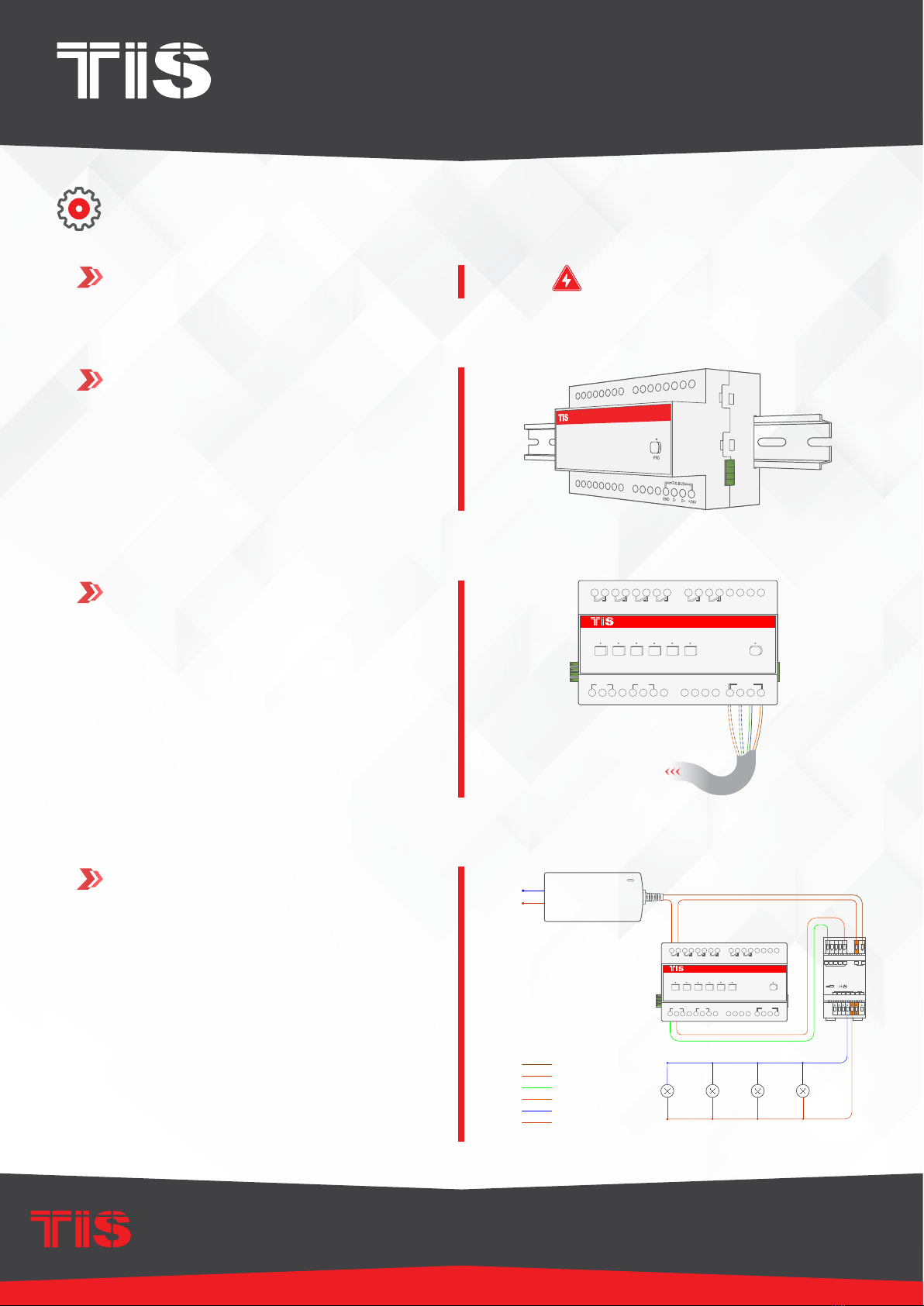
INSTALLATION STEPS
Mount the device on a DIN Rail inside an
approved enclosure. The device can also
be installed without the use of DIN Rail
by two mounting screw holes.
2
+24D+D-GND+24D+D-GND
Connect RS485 data cable to the TIS-
BUS port as per the connection diagram.
No need to loop the TIS-bus cable if 2
DIN Rail modules are connected together
from the side bus train terminal.
3
GND(white-orange)&(white-brown)
D-(white-green)&(white-blue)
D+(blue-green)
+24V(brown-orange)
Cat5e connection
To the TIS BUS Network
Cat5e
RLY-6CH-0-10V
TIS-BUS
GND D- D+ +24V
PRG
1 2 3 4 5 6
CH1
GND
0-10V
GND
0-10V
CH2 CH3 CH4 CH5 CH6
Connect the load (Driver Power) electrical
wires to outputs 1-6. Each channel can
control up to 10A loads. The installer
should make sure not to overload the
device and module channels.
4
1.5 mm Electric Cable
1.5 mm Electric Cable
low voltage cable
low voltage cable
low voltage cable
low voltage cable
PRI:
Uin=12-36VDC
lin=300mA Max
SEC:
LED RLYmer
Uout=16VDC
Iout=250mA Max
TEMP RANGE=-20C-+50C
RoHS
v+ v-
1- + V+ V-
-tc=75c
0.5-1.5mm2
6-7mm
DC Input
4 3 2 1
4- 3- 2-
Pout=4X(80-180)W
GND
DC Input
INPUT1-10V
LED OUTPUT
Connect To N
Connect To L
AC/DC ADAPTER
Input 110~220V AC
Output 12V DC
DC load
RLY-6CH-0-10V
TIS-BUS
GND D- D+ +24V
PRG
1 2 3 4 5 6
CH1
GND
0-10V
GND
0-10V
CH2 CH3 CH4 CH5 CH6

BALLAST CONTROLLER MODULE
INSTALLATION MANUAL
MODEL: RLY-6CH-0-10V
TIS CONTROL LIMITED
RM 1502-p9 Easey CommBldg
253-261 Hennessy Rd Wanchai
Hong Kong
TEXAS INTELLIGENT SYSTEM LLC
SUITE# 610. 860 NORTH DOROTHY DR
RICHARDSON
TX 75081.USA
Copyright © 2020 TIS, All Rights Reserved
TIS Logo is a Registered Trademark of Texas Intelligent System LLC in the
United States of America. This company takes TIS Control Ltd. in other
countries. All of the Specifications are subject to change without notice.
www.tiscontrol.com
6 Channels 0-10V
INSTALLATION STEPS
Connect 0-10V outputs for each channel
to 0-10V drivers’ inputs.
5
1.5 mm Electric Cable
1.5 mm Electric Cable
low voltage cable
low voltage cable
low voltage cable
low voltage cable
PRI:
Uin=12-36VDC
lin=300mA Max
SEC:
LED RLYmer
Uout=16VDC
Iout=250mA Max
TEMP RANGE=-20C-+50C
RoHS
v+ v-
1- + V+ V-
-tc=75c
0.5-1.5mm2
6-7mm
DC Input
4 3 2 1
4- 3- 2-
Pout=4X(80-180)W
GND
DC Input
INPUT1-10V
LED OUTPUT
Connect To N
Connect To L
AC/DC ADAPTER
Input 110~220V AC
Output 12V DC
DC load
RLY-6CH-0-10V
TIS-BUS
GND D- D+ +24V
PRG
1 2 3 4 5 6
CH1
GND
0-10V
GND
0-10V
CH2 CH3 CH4 CH5 CH6
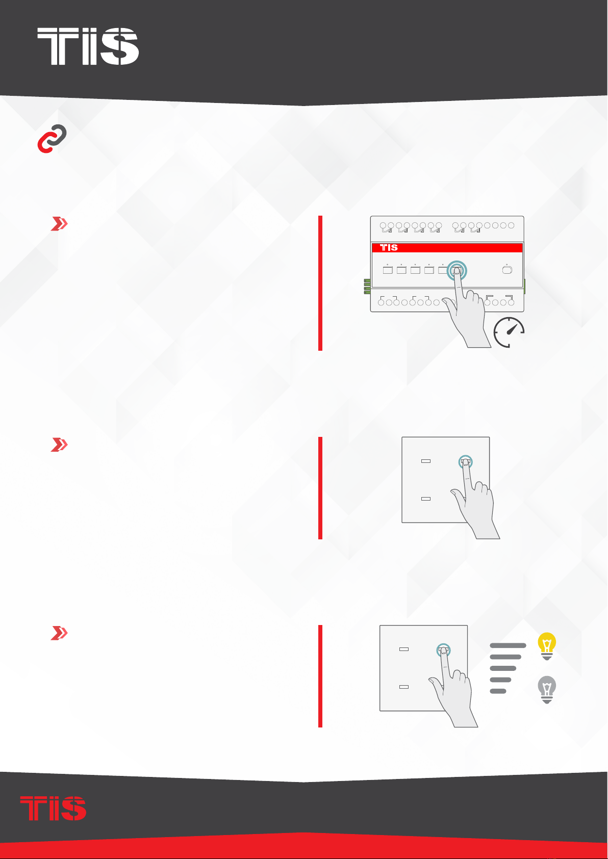
Turn on the power source, and then
test the loads by short pressing on the
device’s local override buttons 1-8.
6
RLY-6CH-0-10V
TIS-BUS
GND D- D+ +24V
PRG
1 2 3 4 5 6
CH1
GND
0-10V
GND
0-10V
CH2 CH3 CH4 CH5 CH6
BALLAST CONTROLLER MODULE
INSTALLATION MANUAL
MODEL: RLY-6CH-0-10V
TIS CONTROL LIMITED
RM 1502-p9 Easey CommBldg
253-261 Hennessy Rd Wanchai
Hong Kong
TEXAS INTELLIGENT SYSTEM LLC
SUITE# 610. 860 NORTH DOROTHY DR
RICHARDSON
TX 75081.USA
Copyright © 2020 TIS, All Rights Reserved
TIS Logo is a Registered Trademark of Texas Intelligent System LLC in the
United States of America. This company takes TIS Control Ltd. in other
countries. All of the Specifications are subject to change without notice.
www.tiscontrol.com
6 Channels 0-10V
You can pair the light channels with any wall panels. To do so, follow these steps:
Test the button on the panel by short
pressing for ON/OFF and Long Press to
dim.
3
TER-4G
45mm
25mm
TER-4G
D-
24V GND
D+
45mm
221
227A
12EM4
227A
12EM4
TER-4G-A
45mm
25mm45mm
TER-4G-A
ADD-3R-5A
ADD-3R-5A
50mm
24mm54mm
PANEL ADDITION
3 Output Relay 5 Amp
Model : ADD-3R-5A
TIS BUS Input : 45-75mA/24V DC
Output Current : 3A220VAC
COM OUT3 OUT2 OUT1 COM
www.tissmarthome.com
D- +24V
GND D+
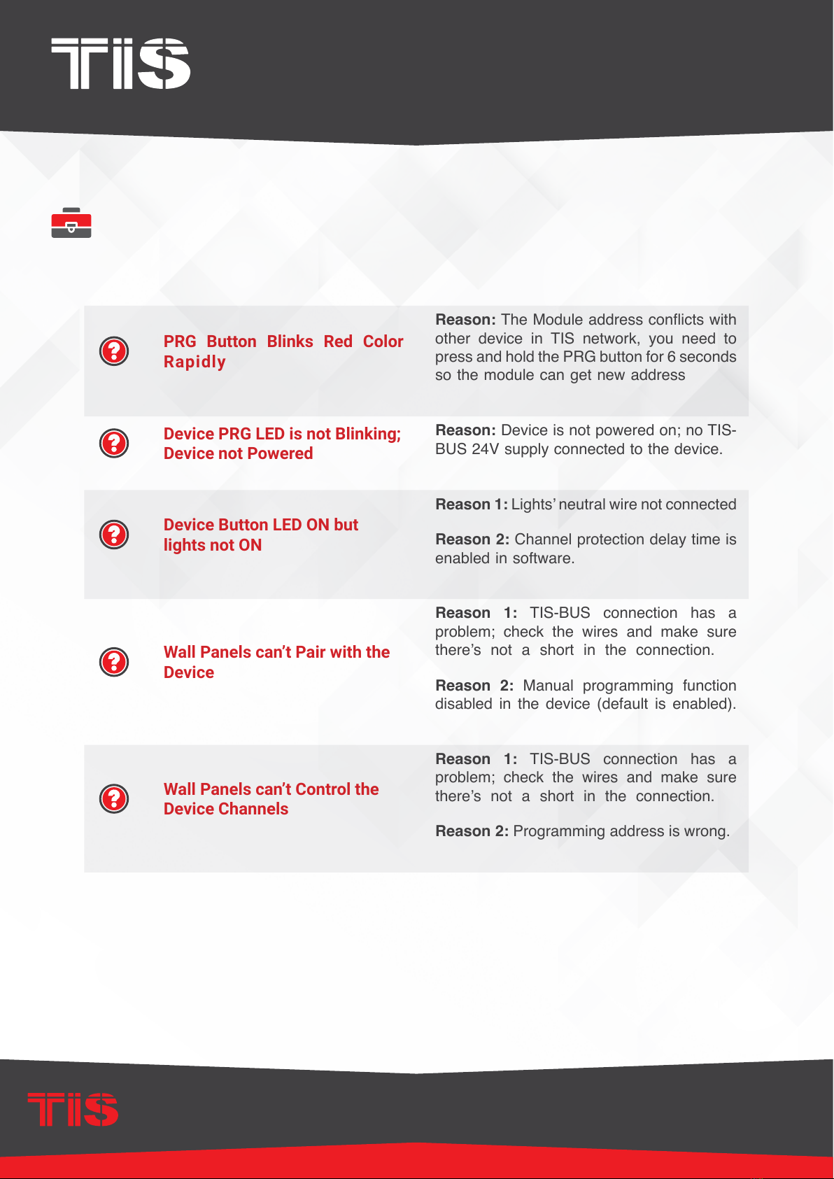
PAIRING (MANUAL PROGRAMMING)
RLY-6CH-0-10V
TIS-BUS
GND D- D+ +24V
PRG
1 2 3 4 5 6
CH1
GND
0-10V
GND
0-10V
CH2 CH3 CH4 CH5 CH6
1Press on any buttons 1-6 for 6 seconds
so that the LED indicator of that button
starts blinking.
6”
Short press on any wall lights buttons on
the Luna, Mars, Terre or others panels.
2
TER-4G
45mm
25mm
TER-4G
D-
24V GND
D+
45mm
221
227A
12EM4
227A
12EM4
TER-4G-A
45mm
25mm45mm
TER-4G-A
ADD-3R-5A
ADD-3R-5A
50mm
24mm54mm
PANEL ADDITION
3 Output Relay 5 Amp
Model : ADD-3R-5A
TIS BUS Input : 45-75mA/24V DC
Output Current : 3A220VAC
COM OUT3 OUT2 OUT1 COM
www.tissmarthome.com
D- +24V
GND D+
BALLAST CONTROLLER MODULE
INSTALLATION MANUAL
MODEL: RLY-6CH-0-10V
TIS CONTROL LIMITED
RM 1502-p9 Easey CommBldg
253-261 Hennessy Rd Wanchai
Hong Kong
TEXAS INTELLIGENT SYSTEM LLC
SUITE# 610. 860 NORTH DOROTHY DR
RICHARDSON
TX 75081.USA
Copyright © 2020 TIS, All Rights Reserved
TIS Logo is a Registered Trademark of Texas Intelligent System LLC in the
United States of America. This company takes TIS Control Ltd. in other
countries. All of the Specifications are subject to change without notice.
www.tiscontrol.com
6 Channels 0-10V
TROUBLESHOOTING
PRG Button Blinks Red Color
Rapidly
Reason: The Module address conicts with
other device in TIS network, you need to
press and hold the PRG button for 6 seconds
so the module can get new address
Device PRG LED is not Blinking;
Device not Powered
Reason: Device is not powered on; no TIS-
BUS 24V supply connected to the device.
Device Button LED ON but
lights not ON
Reason 1: Lights’ neutral wire not connected
Reason 2: Channel protection delay time is
enabled in software.
Wall Panels can’t Pair with the
Device
Reason 1: TIS-BUS connection has a
problem; check the wires and make sure
there’s not a short in the connection.
Reason 2: Manual programming function
disabled in the device (default is enabled).
Wall Panels can’t Control the
Device Channels
Reason 1: TIS-BUS connection has a
problem; check the wires and make sure
there’s not a short in the connection.
Reason 2: Programming address is wrong.
Table of contents
Other TIS Dimmer manuals


Popular Dimmer manuals by other brands

Philio Technology Corporation
Philio Technology Corporation PAD07 Quick user guide

Lite-Puter
Lite-Puter DX-1210 user manual

Lutron Electronics
Lutron Electronics DESIGNER-STYLE WIRED MAESTRO DIMMERS manual

AMX
AMX RDD-DM4/120 Specifications

Linear Technology
Linear Technology Sys-Pro 114460 quick start guide

Hoftronic
Hoftronic 4406530 user manual

MICROPOINT
MICROPOINT mLabs Multi-level D-Dimer Control Level I manual

Ltech
Ltech LT-3200-350 user manual

Universal Remote Control
Universal Remote Control MRFA-3LD-URC installation manual

hager
hager TYA663AN quick start guide

MK
MK Elements Collection installation guide

Crestron
Crestron CLX-1DIM4 Specifications


