Contents
1. Overview........................................................................................................................1
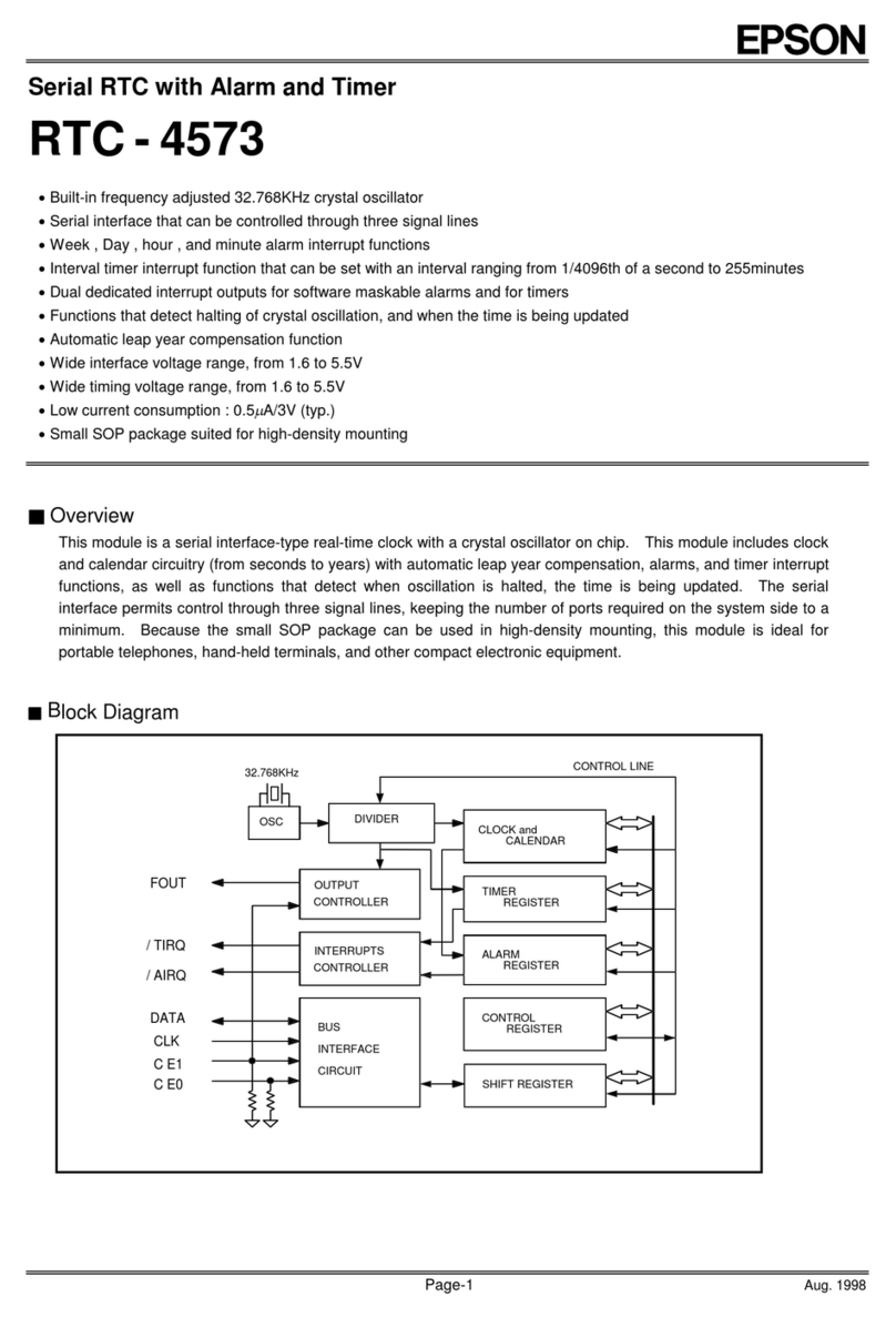
2. Block Diagram ...............................................................................................................1
3. Terminal description .....................................................................................................2
4. Examples of external connection...................................................................................2
5. External Dimensions / Marking Layout...........................................................................3
6.Absolute Maximum Ratings...........................................................................................4
7. Recommended Operating Conditions............................................................................4
8. Frequency Characteristics.............................................................................................4
9.Electrical Characteristics ..............................................................................................5
10. Matters that demand special attention on use..............................................................9
11. Reference information ...............................................................................................11
12. Application notes .......................................................................................................12
13. Overview of Functions and Description of Registers................................................13
13.1. Overview of Functions..................................................................................................................13
13.2. Register table ...............................................................................................................................14
13.3. Description of registers.................................................................................................................15
14. How to use.................................................................................................................17
14.1. Clock calendar explanation ..........................................................................................................17
14.2. Fixed-cycle Timer Interrupt Function............................................................................................18
14.3. Alarm Interrupt Function...............................................................................................................23
14.4. Time Update Interrupt Function....................................................................................................26
14.5. Frequency stop detection function ...............................................................................................28
14.6.FOUT function [clock output function] ..........................................................................................28
14.7. Battery backup switchover function..............................................................................................28
14.8. Reset output function ...................................................................................................................33
14.9. Detection voltage setting..............................................................................................................34
14.10. Digital offset function..................................................................................................................34
14.11. Flow-chart...................................................................................................................................36
14.12. Reading/Writing Data via the I2C Bus Interface .........................................................................40

