Titan Tool Epic 447ex User manual

OWNERS MANUAL
FOR PROFESSIONAL
USE
ONlY
313 •349 REV 6/95
DO
NOT
USE
EQUIPMENT
BEFORE
READING
THIS
MANUAL
•
I
ic
447ex
1
OOV
Pump
Only-~
11
OV
Pump
Only-
1n...~lJIJ
11
OV
Complete -765-310
11
OV
Complete- 765-510
220
V Complete -
7n..........::"H
._
.....
220V
Pump Only
...
1
This manual contains important warnings and instructions
..
Please
read
and
retain for reference.
Never operatethis unit unless it is
property
grounded.

Table
of
Contents
Accessories
General Repairs/Service
Maintenance/Service Record
Warnings
Aviso (En Espaiiol)
Attention (En Frangaise)
2
3
4
5
6
7
Notice: Fire
or
Explosion Hazards
Start-up Procedure
Cleaning Procedure
Flushing Specification
Application Techniques
Airless Tip Selection
8&9
10
11
12
13
14
Trouble Shooting
Spray Pattern
Airless Gun
Airless Pump
LIQUID
SHIELD
14
& 15
Cleans and protects
spray
systems
against rust, corrosion
and
premature
wear.
Case of
12
(1
quart bottles) 700-888
1 Quart 700-889
PISTON
SEAL
LUBRICANT
Specially formulated
to
prevent
materials from adhering
to
the piston
rod, which becomes abrasive to the
UpFJer
seals. Piston Lube will break
down any material that
may
accumulate in the wet cup and keep it
from drying.
8 Oz individual
1 Qt individual
8 Oz, case of 12
1 Qt, case of 12
700-925
700-926
700-911
700-912
Parts Drawings &
Repair Information 16-25
Frame ................................................... 16
Replacement Labels ............................ 16
Unitec Motor ......................................... 18
Armature ...•.......................................... 18
Motor Housing ...................................... 19
Gear
Box
.............................................. 20
Wiring Diagram ....................................
20
Gear Repair Service ............................
21
On/Off Switch ......................................
21
Power Cord Replacement.. ..................
21
Motor Starter ........................................
21
Motor Brush .........................................
21
Accessories
2
Filter Block ...................•.......•..........•.... 22
Pressure Switch .........•..••.•..•..•.............
Pressure Relief Prime Valve •.•...........•.
'--
Filter Replacement & Gun Filer .....•...... 23
Fluid Section Syphon Assembly .......... 24
Upper
(Outlet) Valve
Pump Sect. Repair/Packing
Replacement. .................................... 25
Seat
Service & Repair .......................... 25
Job
History Recording Form ................ 26
Schematic for
220
Volt Units ................ 27
Warranty .............................................. 28
AIRLESS
HOSE
I.D.x Length
1/4" X 50'
3/8" X 50'
3/16" X
3'
3/16" X 9'
3/16" X 15'
Product No.
316-505
690-375-50
550-220
550-222
550-221
HIGH PRESSURE SWIVELS
Pressure Rated a 5000 psi
Gun-to-Hose
1/4" NPS (F) x 1/4" NPS (M) 500-428
Hose-to-Hose
1/4" NPS (M) x 1/4" NPS(M) 500-424
FITTINGS
1/4" x 1/4" Hose Coupling 490-012
1/4" x 3/8" Hose Coupling 490-016
3/8" x 3/8" Hose Coupling 490-014
T-Fittings 490-036
4 Gun Manifold 500-056
Tip Filter Retainer 520-046
1/4" Mx1/4"F Swivel Union 490-005
1/4" Mx3/8"F Swivel Union 490-032
Retaining Nut Adapter 490-007
High Pressure Fl. Gauge 730-235

1
OOV
Pump
Only -765-300
11
OV
Pump
Only -765-500
220V
Pump
Only
...
765-503
1 00 V
Complete
-765-31 0
11
0 V
Complete
...
765-51 0
220V
Complete-
765-510
Motor
Paint Filter
Figure 1
General
Repair & rvice Notes:
WARNING: Before proceeding, follow the Pressure
Relief Procedure outlined on Page
5.
Additionally,
follow all other warnings
to
reduce the risk
of
an
injection injury, injury from moving parts
or
electric
shock. Always unplug the sprayer before servicing!
The following tools are needed when repairing this
sprayer:
Phillips Screwdriver
Needle Nose Pliers
Adjustable· Wrench
Rubber Mallet
Flat-blade Screwdriver
1/2
11
Open End Wrench
3/8
11
AIIen Wrench
5/16~'
Allen Wrench
1/4
11
Allen Wrench
3/16
11
Allen Wrench
1/8
11
Allen Wrench
~.
Befo~e
repairing any part of the sprayer, read the
mstruct1ons carefully, including all warnings.
2. When disconnecting wires, use needle nose pliers to
separate mating connectors. 3
Pressure Control
Add P
.S.l.
Here
(Piston Seal
lubricant)
Fluid Section
CAUTION: Never pull
on
a wire
to
disconnect
it.
Pulling on a wire could loosen the connector from the
wire.
3.
Test your repair before regular operation of the sprayer
to be sure that the problem is corrected. If the sprayer
does not operate properly, review the repair procedure to
determine if everything was done correctly. Refer to the
Troubleshooting Charts
to
help identify other possible
problems.
4. Make certain that the service area is well ventilated in
case solvents are used during cleaning. Always wear
protective eyewear while servicing. Additional protective
equipment may be required depending on
th~
type of
cleaning solvent. Always contact the supplie·r of solvents
for recommendations.
5. If you have any further questions concerning your
TITAN Airless Sprayer, call TITAN Customer Service
Department at 1-SOQ-526-5362.

MODEL#
SERIAL#
DATE
PURCHASED
COMPANY
NAME
Titan
Tool
is
in
the
business
of
designing
and
manufacturing
spray
systems
and
accessories
that
make
today's
Painting
Professional
become
more efficient
and
profitable.
We
feel
that
if
you
accurately track
the
maintenance
of
your
equipment
on
this
chart it will improve the
periormance
of
this
valuable
tool
to
help
you
get
the
most
out
of
your
investment .
The
chart
is
easy
to
follow
and
to
use.
The
Maintenance
Schedule allows
for
the
recording
of
all
your service
work
and
will
help
you
make
sure
your
unit
is always running
at
peak
pertormance.
Make
sure
to
fill
in
the boxes at
the
top of this
record
with
the
model
number,
serial
number,
date
purchased
and
your
company
name.
This
information will
be
needed
to
validate
your
warranty.
Maintenance Sch ule
Check Piston Seal
Lubricant
Level
WEEKLY
..
Gas Engine Models
Change
Engine
Oil
Dale
Date
Date
Date
Dale
Date
Date
Date
Date Date
!Every
50
Hours
Clean
Air
Filter Daily
It
is extremely important to clean the air filter daily. Consult the Honda Engine Manual supplied
with
your unit for proper
cleaning instructions.
Date Date
Date
Dale
Date
Date
Date
Date
Date
Date
Air
Filter
Replaced
Electric Motor Models
Chec~
Motor
Date
Date
Date
Date
Date
Date
Date
Date
Date Date
Brushes
Every
200
Hours
Service Record
Date Service Center Service Performed Warranty
Repair
Months in Service Cost of Repair 0 Yes
0 No
Date Service Center Service Performed Warranty
Repair
Months in Service Cost of Repair 0 Yes
0 No
Date Service Center Service Performed Warranty
Repair
~!.::mths
in Service Cost
of
Repair 0 Yes
0 No
Date Service Center Service Performed Warranty
Repair
Months in Service Cost
of
Repair 0 Yes
0 No
Date Service Center Service Performed Warranty
Repair
Months in Service Cost of Repair 0 Yes
0 No
·May Be
Copied
For
Field Use
4

DO NOT USE EQUIPMENT BEFORE READING THIS SECTION
I
HI
H P ESSURE SPRAY
CAN CAUSE SERI
US
INJURY
Maximum Working Pressure 3000 psi,
210
bar
An
airless spray gun requires that fluid
be introduced to it at very high pressure.
Fluids under high pressure, from spray or
leaks, can penetrate the skin and inject
substantial quantities of toxic fluid into
the body. If not promptly and properly
treated, the injury can cause tissue death
or gangrene and may result in serious,
permanent disability or amputation of the
wounded part. Therefore, extreme
caution must be exercised when using
any airless spray equipment. IF YOU
ARE INJECTED, SEE A PHYSICIAN
IMMEDIATELY.
DO
NOT TREAT AS A
SIMPLE CUT!
NOTE TO PHYSICIAN: Injection into
the skin is a serious, traumatic injury.
It
is
important to treat the injury surgically as
soon as possible. Do not delay treatment
to research toxicity. Toxicity
is
a concern
with some exotic coatings injected
directly· into the bloodstream.
Consultation with a plastic surgeon or a
reconstructive hand surgeon may be
advised.
1 ) Handle the spray gun carefully.
Keep clear of the nozzle. NEVER point
the gun at yourself or anyone else.
NEVER permit any part of your body to
come in contact with the fluid stream of
either the gun
or
any hose leak.
ALWAYS keep the gun trigger safety
lever in a locked position when not
spraying.
ALWAYS
use a tip safety
guard.
2) NEVER attempt to force the flow of
fluid backward through the gun with your
finger, hand or hand-held object against
the gun nozzle. THIS IS NOT AN AIR
SPRAY GUN.
3) NEVER attempt to remove tip,
disassemble
or
repair equipment without
first doing the following:
PRESSURE
RELEASE
PROCEDURE
A.
Set
trigger
safety
in
a
locked
position.
B.
Shut
off
pump
and
unplug
electrical
cord.
C.
Release
fluid
pressure
from
entire
system
and
trigger
gun.
D.
Reset
trigger
safety
in
a
locked
position.
4)
Before flushing system, always
remove spray tip and adjust fluid pressure
to lowest possible setting.
5)
Tighten all fluid connections before
each use. NEVER exceed 3000 psi with
this unit. Make sure that all accessory
hoses, connections, swivels and so forth
can withstand the high pressures which
develop. NEVER exceed the pressure
rating of any component
in
the system.
6)
WARNING:
The
paint hose can
develop leaks from wear, kinking, abuse,
etc. A leak is capable of injecting fluid into
the skin, therefore
the
paint hose should
be inspected before each use. NEVER
attempt to plug a hose with any part of
your body, adhesive tape or any other
makeshift device.
Do
not attempt to
repair a spray hose. Instead, replace it
with a new grounded hose.
Use
only with
hoses that have spring guards. NEVER
use less than 50' of hose with this unit.
7)
Be
sure that
the
airless equipment
being used and the object being sprayed
are properly grounded to prevent static
discharge or sparks which could cause
fire or explosion. WARNING: ALWAYS
hold the gun against metal container
when flushing system with tip removed, to
prevent static discharge. CAUTION: To
reduce the risk of electrical shock,
do
not
expose to rain. Store indoors.
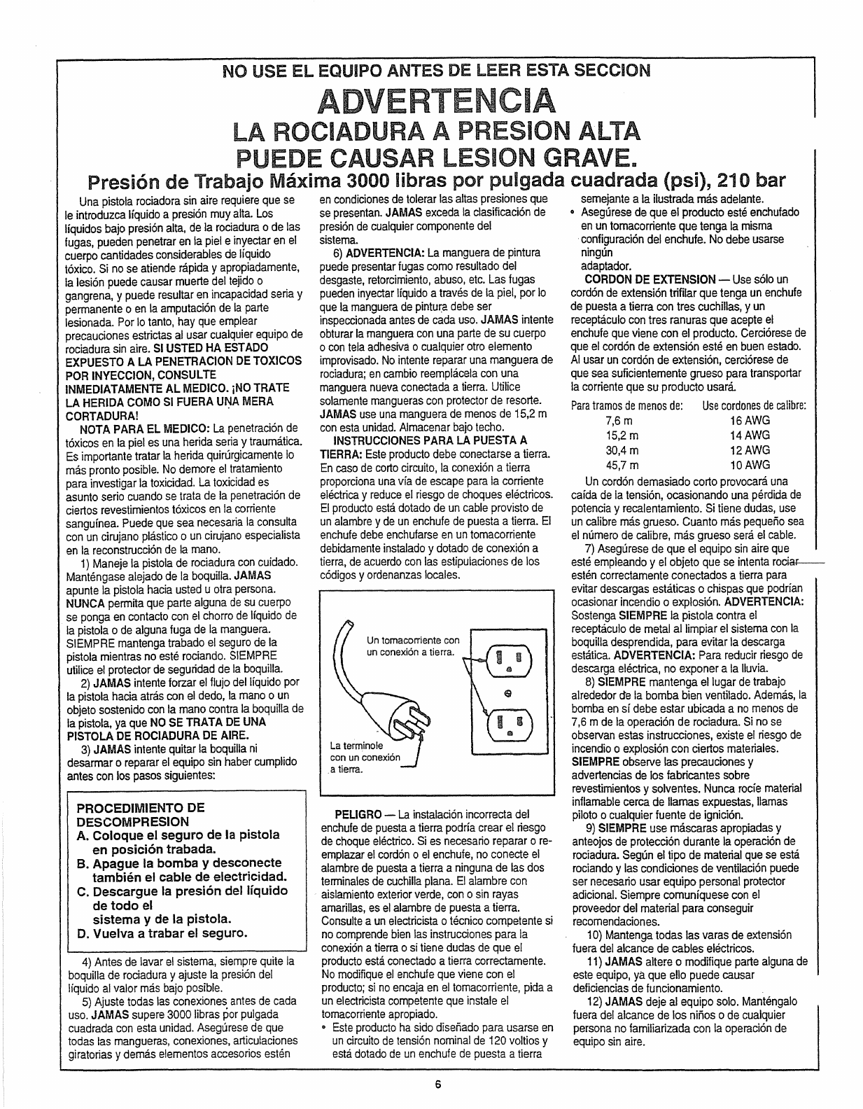
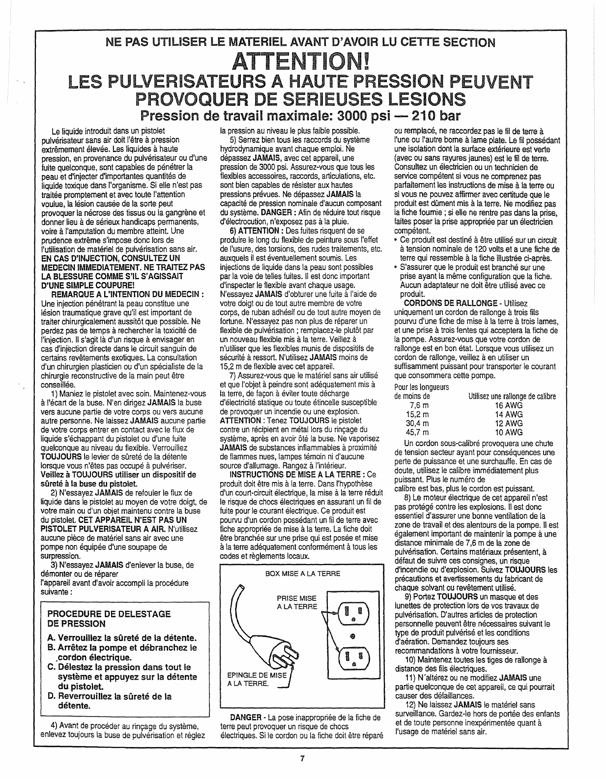
GROUNDING INSTRUCTIONS: This
product should
be
grounded.
In
the event
of
an
electrical short circuit, grounding
reduces the risk of electric shock by
providing an escape wire for the electric
current. This product is equipped with a
cord having a grounding wire with
an
appropriate grounding plug.The plug must
be plugged into
an
outlet that
is
properly
GROUND
OUTLET BOX
GROUNDED
OUTLET
installed and grounded
in
accordance
with all local codes and ordinances.
DANGER-
Improper installation
of
the
grounding plug can result
in
a risk of
electric shock.
If
repair or replacement of
the cord or plug is necessary,
do
not
connect the grounding wire to either flat
blade terminal. The wire with insulation
having
an
outer surtace that is green
(with or without yellow stripes)
is
the
grounding wire. Check with a qualified
electrician or serviceman if the grounding
5
instructions are not completely
understood, or if
in
doubt as to whether
the product is properly grounded. Do not
modify the plug provided; if it will not fit
the outlet, have the proper outlet installed
by a qualified electrician.
• This product is for use on a nominal
120-volt circuit and has a grounding
plug that looks like the plug illustrated
below.
• Make sure that the product is
connected to an outlet having the same
configuration as the plug. No adapter
should be used with this product.
EXTENSION CORDS: Use only a 3-
wire extension cord that has a 3-slot
receptacle that will accept the plug on the
pump. Make sure your extension cord is
in
good condition. Wben using
an
extension cord, be sure to use one heavy
enough to carry the current this pump will
draw.
For
lengths
less
than
25ft.
50
ft.
100ft.
150ft.
Use
extension
gauge
16AWG
14AWG
12AWG
10AWG
An
undersized cord will cause a drop in
line voltage resulting
in
loss of power and
overheating. If in doubt, use the next
heavier gauge. The smaller the gauge
number, the heavier the cord.
8)
ALWAYS
keep the working area
around the pump well ventilated.
Additionally, the pump itself should be a
minimum of 25' (7.5m) from the spray
area. If these instructions are not
followed, there is the possibility of fire
or
explosion with certain materials.
ALWAYS follow the coating
or
solvent
manufacturer's safety precautions and
warnings. Never spray flammable
material near open flames, pilot lights
or
any source of ignition.
9)
ALWAYS
wear spray masks and
protective eyewear while spraying.
Additional personal protective
equipme11t
may
be
required depending on the type of
material being sprayed and conditions of
ventilation. Always contact supplier of
material being sprayed for
recommendation.
1
0)
Keep all extension poles clear of
electrical wires.
11) NEVER alter or modify any part of
this equipment; doing so could cause it to
malfunction.
12) NEVER leave equipment
unattended. Keep away from children or
anyone not familiar with the operation of
airless equipment.

NO USE
EL
EQUIPO ANTES DE LEER ESTA SECCION
I
I N A
PUE E CAUSAR LESI N GRAVE.
Presion
de
Trabajo Maxima 3000 Iibras
por
pulgada cuadrada (psi),
21
o bar
Una
pistola
rociadora
sin
aire
requiere
que
se
le
introduzca
llquido
a
presion
muy
alta.
Los
liquidos
bajo
presion
alta,
de
Ia
rociadura
o
de
las
fugas,
pueden
penetrar
en
Ia
piel
e
inyectar
en
el
cuerpo
cantidades
considerables
de
liquido
toxico.
Si
no
se
atiende
rapida
y
apropiadamente,
Ia
lesion
puede
causar
muerte
del
tejido
o
gangrena,
y
puede
resultar
en
incapacidad
seria
y
permanente
o
en
Ia
amputacion
de
Ia
parte
lesionada.
Por
lo
tanto,
hay
que
emplear
precauciones
estrictas
al
usar
cualquier
equipo.
de
rociadura
sin
aire.
Sl
USTED
HA
EST
ADO
EXPUESTO
A
LA
PENETRACION
DE
TOXICOS
POR
INYECCION,
CONSULTE
INMEDIATAMENTE
AL
MEDICO.
iNO
TRATE
LA
HERIDA
COMO
Sl
FUERA
U~A
MERA
CORTADURA!
NOTA
PARA
EL
MEDICO:
La
penetracion
de
toxicos
en
Ia
piel
es
una
herida
seria
y
traumatica.
Es
importante
tratar
Ia
herida
quirurgicamente
lo
mas
pronto
posible.
No
demore
el
tratamiento
para
investigar
Ia
toxicidad.
La
toxicidad
es
asunto
serio
cuando
se
trata
de
Ia
penetracion
de
ciertos
revestimientos
toxicos
en
Ia
corriente
sanguinea.
Puede
que
sea
necesaria
Ia
consulta
con
un
cirujano
plastico
o
un
cirujano
especialista
en
Ia
reconstruccion
de
Ia
mano.
1)
Maneje
Ia
pistola
de
rociadura
con
cui
dado.
Mantengase
alejado
de
Ia
boquilla.
JAMAS
apunte
Ia
pistola
hacia
usted
u
otra
persona.
NUNCA
permita
que
parte
alguna
de
su
cuerpo
se
ponga
en
contacto
con
el
chorro
de
lfquido
de
Ia
pistola
o
de
alguna
fuga
de
Ia
manguera.
SIEMPRE
mantenga
trabado
el
seguro
de
Ia
pistola
mientras
no
este
rociando.
SIEMPRE
utilice
el
protector
de
seguridad
de
Ia
boquilla.
2)
JAMAS
intente
forzar
el
flujo
delliquido
por
Ia
pistola
hacia
atras
con
el
dedo,
Ia
mano
o
un
objeto
sostenido
con
Ia
mano
contra
Ia
boquilla
de
Ia
pistola,
ya
que
NO
SE
TRATA
DE
UNA
PISTOLA
DE
ROCIADURA
DE
AIRE.
3)
JAMAS
intente
quitar
Ia
boquilla
ni
desarmar
o
reparar
el
equipo
sin
haber
cumplido
antes
con
los
pasos
siguientes:
PROCEDIMIENTO DE
DESCOMPRESION
A. Coloque el seguro de Ia pistola
en posicion trabada.
B. Apague Ia
bombay
desconecte
tambh~n
el cable de electricidad.
C.
Descargue
Ia
presion del lfquido
de
todo
el
sistema y de Ia pistola.
D.
Vuelva a trabar el seguro.
4)
Antes
de
lavar
el
sistema,
siempre
quite
Ia
boquilla
de
rociadura
y
ajuste
Ia
presion
del
lfquido
al
valor
mas
bajo
posible.
5)
Ajuste
todas
las
conexiones
antes
de
cada
uso.
JAMAS
supere
3000
Iibras
por
pulgada
cuadrada
con
esta
unidad.
Asegurese
de
que
todas
las
mangueras,
conexiones,
articulaciones
giratorias
y
demas
elementos
accesorios
esten
en
condiciones
de
tolerar
las
altas
presiones
que
se
presentan.
JAMAS
exceda
Ia
clasificacion
de
presion
de
cualquier
componente
del
sistema.
6)
ADVERTENCIA:
La
manguera
de
pintura
puede
presentar
fugas
como
resultado
del
desgaste,
retorcimiento,
abuso,
etc.
Las
fugas
pueden
inyectar
liquido
a
traves
de
Ia
piel,
por
lo
que
Ia
manguera
de
pintu~a
debe
ser
inspeccionada
antes
de
cada
uso.
JAMAS
intente
obturar
Ia
manguera
con
una
parte
de
su
cuerpo
o
con
tela
adhesiva
o
cualquier
otro
elemento
improvisado.
No
intente reparar
una
manguera
de
rociadura;
en
cambio
reemplacela
con
una
manguera
nueva
conectada
a
tierra.
Utilice
solamente
mangueras
con
protector
de
resorte.
JAMAS
use
una
manguera
de
menos
de
15,2
m
con
esta
unidad.
Almacenar
bajo
techo.
INSTRUCCIONES
PARA
LA
PUESTA
A
TIERRA:
Este
producto
debe
conectarse
a
tierra.
En
caso
de
corto
circuito,
Ia
conexion
a
tierra
proporciona
una
vfa
de
escape
para
Ia
corriente
ehktrica
y
reduce
el
riesgo
de
choques
electricos.
El
producto
esta
dotado
de
un
cable
provisto
de
un
alambre
y
de
un
enchufe
de
puesta
a
tierra.
El
enchufe
debe
enchufarse
en
un
tomacorriente
debidamente
instalado
y
dotado
de
conexion
a
tierra,
de
acuerdo
con
las
estipuiaciones
de
los
codigos
y
ordenanzas
locales.
Un tomacorriente con
un conexi6n a tierra.
PELIGRO
-
La
instalacion
incorrecta
del
enchufe
de
puesta
a
tierra
podrfa
crear
el
riesgo
de
choque
electrico.
Si
es
necesario
reparar
ore-
emplazar
el
cordon
o
el
enchufe,
no
conecte
el
alambre
de
puesta
a
tierra
a
ninguna
de
las
dos
terminales
de
cuchilla
plana.
El
alambre
con
aislamiento
exterior
verde,
con
o
sin
rayas
amarillas,
es
el
alambre
de
puesta
a
tierra.
Consulte
a
un
electricista
o
tecnico
competente
si
no
comprende
bien
las
instrucciones
para
Ia
conexi6n
a
tierra
o
si
tiene
dudas
de
que
el
producto
esta
conectado
a
tierra
correctamente.
No
modifique
el
enchufe
que
viene
con
el
producto;
si no
encaja
en
el
tomacorriente,
pida
a
un
electricista
competente
que
instale
el
tomacorriente
apropiado.
"
Este
producto
ha
sido
diseflado
para
usarse
en
un
circuito
de
tension
nominal
de
120
voltios
y
esta
dotado
de
un
enchufe
de
puesta
a
tierra
6
semejante
a
Ia
ilustrada
mas
adelante.
•
Asegurese
de
que
el
producto
este
enchufado
en
un
tomacorriente
que
tenga
Ia
misma
configuracion
del
enchufe.
No
debe
usarse
ningun
adaptador.
CORDON
DE
EXTENSION-
Use
solo
un
cordon
de
extension
trifilar
que
tenga
un
enchufe
de
puesta
a
tierra
con
tres
cuchillas,
y
un
receptacula
con
tres
ranuras
que
acepte
el
enchufe
que
viene
con
el
producto.
Cerciorese
de
que
el
cordon
de
extension
este
en
buen
estado.
AI
usar
un
cordon
de
extension,
cerciorese
de
que
sea
suficientemente
grueso
para
transportar
Ia
corriente
que
su
producto
usara
Para
tramos
de
menos
de:
Use
cordones
de
calibre:
7,6
m
16AWG
15,2
m
14
AWG
30,4
m
12AWG
45,7m
10AWG
Un
cordon
demasiado
corto
provocara
una
cafda
de
Ia
tension,
ocasionando
una
perdida
de
potencia
y
recalentamiento.
Si
tiene
dudas,
use
un
calibre
mas
grueso.
Cuanto
mas
pequefio
sea
el
numero
de
calibre,
mas
grueso
sera
el
cable.
7)
Asegurese
de
que
el
equipo
sin
aire
que
este
empleando
y
el
objeto
que
se
intenta
rocial:--
esten
correctamente
conectados
a
tierra
para
evitar
descargas
estaticas
o
chispas
que
podrfan
ocasionar
incendio
o
explosion.
ADVERTENCIA:
Sostenga
SIEMPRE
Ia
pistola
contra
el
receptacula
de
metal
al
limpiar
el
sistema
con
Ia
boquilla desprendida,
para
evitar
Ia
descarga
estatica.
ADVERTENCIA:
Para
reducir
riesgo
de
descarga
electrica,
no
exponer
a
Ia
lluvia.
8)
SIEMPRE
mantenga
ellugar
de
trabajo
alrededor
de
Ia
bomba
bien
ventilado.
Ademas,
Ia
bomba
en
sf
debe
estar
ubicada
a
no
menos
de
7,6
m
de
Ia
operacion
de
rociadura.
Sino
se
observan
estas
instrucciones,
existe
el
riesgo
de
incendio
o
explosion
con
ciertos
materiales.
SIEMPRE
observe
las
precauciones
y
advertencias
de
los
fabricantes
sobre
revestimientos
y
solventes.
Nunca
rocie
material
inflamable
cerca
de
llamas
expuestas,
llamas
piloto
o
cualquier
fuente
de
ignici6n.
9)
SIEMPRE
use
mascaras
apropiadas
y
anteojos
de
proteccion
durante
Ia
operacion
de
rociadura.
Segun
el
tipo
de
material
que
se
esta
rociando
y
las
condiciones
de
ventilacion
puede
ser
necesario
usar
equipo
personal
protector
adicional.
Siempre
comuniquese
con
el
proveedor
del
material
para
conseguir
recomendaciones.
1
0)
Mantenga
todas
las
varas
de
extension
fuera
del
alcance
de
cables
electricos.
11)
JAMAS
altere
o
modifique
parte
alguna
de
este
equipo,
ya
que
ello
puede
causar
deficiencias
de
funcionamiento.
12)
JAMAS
deje
al
equipo
solo.
Mantengalo
fuera
del
alcance
de
los
nifios
o
de
cualquier
persona
no
familiarizada
con
Ia
operacion
de
equipo
sin
aire.

NE PAS UTILISER LE MATERIEL AVANT D'AVOIR
LUCETTE
SECTION
I !
LES PULVERISATE
SA
TEPRESSI N PEUVENT
NS
v u R
DE
SERIEUSES LESI
Pression de travail maxim ale: 3000 psi -210 bar
Le
liquide
introduit
dans
un
pistolet
pulverisateur
sans
air
doit
l'etre
a
pression
extremement
elevee.
Les
liquides
a
haute
pression,
en
provenance
du
pulverisateur
ou
d'une
fuite
quelconque,
sont
capables
de
penetrer
Ia
peau
et
d'injecter
d'importantes
quantites
de
liquide
toxique
dans
l'organisme.
Si
elle
n'est
pas
traitee
promptement
et
avec
toute
!'attention
voulue,
Ia
lesion
causae
de
Ia
sorte
peut
provoquer
Ia
necrose
des
tissus
ou
Ia
gangrene
et
donner
lieu
a
de
serieux
handicaps
permanents,
voire
a
!'amputation
du
membre
atteint.
Une
prudence
extreme
s'impose
done
tors
de
!'utilisation
de
materiel
de
pulverisation
sans
air.
EN
CAS
D'INJECTION,
CONSUL
TEZ
UN
MEDECIN
IMMEDIATEMENT.
NE
TRAITEZ
PAS
LA
BLESSURE
COMME
S'IL
S'
AGISSAIT
D'UNE
SIMPLE
COUPURE!
REMARQUE
A
L'INTENTION
OU
MEDECIN
:
Une
injection
penetrant
Ia
peau
constitue
une
lesion
traumatique
grave
qu'il
est
important
de
traiter
chirurgicalement
aussit6t
que
possible.
Ne
perdez
pas
de
temps
a
rechercher
Ia
toxicite
de
!'injection.
II
s'agit
Ia
d'un
risque
a
envisager
en
cas
d'injection
directe
dans
le
circuit
sanguin
de
certains
revetements
exotiques.
La
consultation
d'un
chirurgien
plasticien
ou
d'un
specialiste
de
Ia
chirurgie
reconstructive
de
Ia
main
peut
etre
conseillee.
1)
Maniez
le
pistolet
avec
soin.
Maintenez-vous
a
l'ecart
de
Ia
buse.
N'en
dirigez
JAMAIS
Ia
buse
vers
aucune
partie
de
votre
corps
ou
vers
aucune
autre
personne.
Ne
laissez
JAMAIS
aucune
partie
de
votre
corps
entrer
en
contact
avec
le
flux
de
liquide
s'echappant
du
pistolet
ou
d'une
fuite
quelconque
au
niveau
du
flexible.
Verrouillez
TOUJOURS
le
levier
de
sOrete
de
Ia
detente
lorsque
vous
n'etes
pas
occupe
a
pulveriser.
Veillez a
TOUJOURS
utiliser
un
dispositif
de
sOrete
a
Ia
buse
du
pistolet.
2)
N'essayez
JAMAIS
de
refouler
le
flux
de
liquide
dans
le
pistolet
au
moyen
de
votre
doigt,
de
votre
main
ou
d'un
objet
maintenu
contre
Ia
buse
du
pistolet.
CET
APPAREIL
N'EST
PAS
UN
PISTOLET
PULVERISATEUR
A
AIR.
N'utiiisez
aucune
piece
de
materiel
sans
air
avec
une
pompe
non
equipee
d'une
soupape
de
surpression.
3}
N'essayez
JAMAIS
d'enlever
Ia
buse,
de
demonter
ou
de
reparer
l'appareil
avant
d'avoir
accompli
Ia
procedure
suivante:
PROCEDURE DE DELESTAGE
DE PRESSION
A.
Verrouillez
Ia
suretE~
de
Ia
detente.
B.
Arretez
Ia
pompe et debranchez le
. cordon electrique.
C.
Delestez
Ia
pression dans
tout
le
systeme et appuyez
sur
Ia
detente
du
pistolet.
D.
Reverrouillez
Ia
surete de Ia
detente.
4)
Avant
de
proceder
au
rinyage
du
systeme,
enlevez
toujours
Ia
buse
de
pulverisation
et
reglez
Ia
pression
au
niveau
le
plus
faible
possible.
5)
Serrez
bien
tous
les
raccords
du
systeme
hydrodynamique
avant
chaque
emploi.
Ne
depassez
JAMAIS,
avec
cet
appareil,
une
pression
de
3000
psi.
Assurez-vous
que
tous
les
flexibles
accessoires,
raccords,
articulations,
etc.
sont
bien
capables
de
resister
aux
hautes
pressions
prevues.
Ne
depassez
JAMAIS
Ia
capacite
de
pression
nominale
d'aucun
composant
du
systeme.
DANGER
:
Afin
de
reduire
tout
risque
d'electrocution,
n'exposez
pas
a
Ia
pluie.
6)
ATTENTION
:
Des
fuites
risquent
de
se
produire
le
long
du
flexible
de
peinture
sous
l'effet
de
l'usure,
des
torsions,
des
rudes
traitements,
etc.
auxquels
il
est
eventuellement
soumis.
Les
injections
de
liquide
dans
Ia
peau
sont
possibles
par
Ia
voie
de
telles
fuites.
II
est
done
important
d'inspecter
le
flexible
avant
chaque
usage.
N'essayez
JAMAIS
d'obturer
une
fuite
a
I'
aide
de
votre
doigt
ou
de
tout
autre
membre
de
votre
corps,
de
ruban
adhesif
ou
de
tout
autre
moyen
de
fortune.
N'essayez
pas
non
plus
de
reparer
un
flexible
de
pulverisation;
remplacez-le
plutot
par
un
nouveau
flexible
mis
a
Ia
terre.
Veillez
a
n'utiliser
que
les
flexibles
munis
de
dispositifs
de
securite
a
ressort.
N'utilisez
JAMAIS
moins
de
15,2
m
de
flexible
avec
cet
appareil.
7)
Assurez-vous
que
le
materiel
sans
air
utilise
et
que
l'objet
a
peindre
sont
adequatement
mis
a
Ia
terre,
de
fa9on
a
eviter
toute
decharge
d'electricite
statique
ou
toute
etincelle
susceptible
de
provoquer
un
incendie
ou
une
explosion.
ATTENTION:
Tenez
TOUJOURS
le
pistolet
centre
un
recipient
en
metal
lors
du
rim;age
du
systeme,
apres
en
avoir
6te
Ia
buse.
Ne
vaporisez
JAMAIS
de
substances
inflammables
a
proximite
de
flammes
nues,
lampes
temoin
ni
d'aucune
source
d'allumage.
Rangez
a
l'interieur.
INSTRUCTIONS
DE
MISE
A
LA
TERRE
:
Ce
produit
doit
etre
mis
a
Ia
terre.
Dans
!'hypothese
d'un
court-circuit
electrique,
Ia
mise
a
Ia
terre
reduit
le
risque
de
chocs
electriques
en
assurant
un
fil
de
fuite
pour
le
courant
electrique.
Ce
produit
est
pourvu
d'un
cordon
possedant
un
fil
de
terre
avec
fiche
appropriee
de
mise
a
Ia
terre.
La
fiche
doit
etre
branchee
sur
une
prise
qui
est
posee
et
mise
a
Ia
terre
adequatement
conformement
a
tous
les
codes
et
reglements
locaux.
BOX MISE A
LA
TERRE
PRISE MISE
ALA
TERRE
DANGER
-
La
pose
inappropriee
de
Ia
fiche
de
terre
peut
provoquer
un
risque
de
chocs
electriques.
Si
le
cordon
ou
Ia
fiche
doit
etre
n§pare
7
ou
remplace,
ne
raccordez
pas
le
til
de
terre
a
l'une
ou
!'autre
borne
a
lame
plate.
Le
til
possedant
une
isolation
dont
Ia
surface
exterieure
est
verte
(avec
ou
sans
rayures
jaunes)
est
le
fil
de
terre.
Consultez
un
electricien
ou
un
technicien
de
service
competent
si
vous
ne
comprenez
pas
parfaitement
les
instructions
de
mise
a
Ia
terre
ou
si
vous
ne
pouvez
affirmer
avec
certitude
que
le
produit
est
dOment
mis
a
Ia
terre.
Ne
modifiez
pas
Ia
fiche
foumie
;
si
elle
ne
rentre
pas
dans
Ia
prise,
faites
poser
Ia
prise
appropriee
par
un
electricien
competent.
•
Ce
produit
est
destine
a
etre
utilise
sur
un
circuit
a
tension
nominale
de
120
volts
et
a
une
fiche
de
terre
qui
ressemble
a
Ia
fiche
illustree
ci-apres.
"
S'assurer
que
le
produit
est
branche
sur
une
prise
ayant
Ia
meme
configuration
que
Ia
fiche.
Aucun
adaptateur
ne
doit
etre
utilise
avec
ce
produit.
CORDONS
DE
RALLONGE
-
Utilisez
uniquement
un
cordon
de·rallonge
a
trois
fils
pourvu
d'une
fiche
de
mise
a
Ia
terre
a
trois
lames,
et
une
prise
a
trois
fentes
qui
acceptera
Ia
fiche
de
Ia
pompe.
Assurez-vous
que
votre
cordon
de
rallonge
est
en
bon
etat.
Lorsque
vous
utilisez
un
cordon
de
rallonge,
veillez
a
en
utiliser
un
suffisamment
puissant
pour
transporter
le
courant
que
consommera
cette
pompe.
Pour
les
longueurs
de
mains
de
7,6m
15,2
m
30,4
m
45,7
m
Utilisez
une
rallonge
de
calibre
16AWG
14AWG
12AWG
10AWG
Un
cordon
sous-calibre
provoquera
une
chute
de
tension
secteur
ayant
pour
consequences
une
perte
de
puissance
et
une
surchauffe.
En
cas
de
doute,
utilisez
le
calibre
immediatement
plus
puissant.
Plus
le
numero
de
calibre
est
bas,
plus
le
cordon
est
puissant.
8)
Le
moteur
electrique
de
cet
appareil
n'est
pas
protege
centre
les
explosions.
II
est
done
essentiel
d'assurer
une
bonne
ventilation
de
Ia
zone
de
travail
et
des
alentours
de
Ia
pompe.
II
est
egalement
important
de
maintenir
Ia
pompe
a
une
distance
mini
male
de
7,6
m
de
Ia
zone
de
pulverisation.
Certains
materiaux
presentent,
a
defaut
de
suivre
ces
consignes,
un
risque
d'incendie
ou
d'explosion.
Suivez
TOUJOURS
les
precautions
et
avertissements
du
fabricant
de
chaque
solvant
ou
revetement
utilise.
9)
Portez
TOUJOURS
un
masque
et
des
lunettes
de
protection
tors
de
vos
travaux
de
pulverisation.
D'autres
articles
de
protection
personnelle
peuvent
etre
necessaires
suivant
le
type
de
produit
pulverise
et
les
conditions
d'aeration.
Demandez
toujours
ses
recommandations
a
votre
foumisseur
.
1
0)
Maintenez
toutes
les
tiges
de
rallonge
a
distance
des
fils
electriques.
11)
N •
alterez
ou
ne
modifiez
JAMAIS
une
partie
quelconque
de
cet
appareil,
ce
qui
pourrait
causer
des
defaillances.
12)
Ne
laissez
JAMAIS
le
materiel
sans
surveillance.
Gardez-le
hors
deportee
des
enfants
et
de
toute
personne
inexperimentee
quant
a
!'usage
de
materiel
sans
air.

FIRE OR EXPLOSION HAZARD
Static electricity is created by the high velocity of fluid through the pump, hose and tip. If every part of the spray element
is not properly grounded, sparking may occur
and
the system may become hazardous. Sparking may also occur when
plugging
in
or unplugging a power supply cord, or starting a gas engine. Sparks can ignite fumes from solvents or the
fluids being sprayed. Always plug the sprayer into
an
outlet at least 25' away from the spray area. WARNING: Always
flush
the
unit
into a separate metal container
with
the spray tip removed and
the
gun
held
firmly
against
the
side
of
the
container
to
assure
proper
grounding and prevent static discharge
which
could
cause
serious
bodily
injury.
If
you experience any static sparking or slight shock while using this equipment, stop spraying immediately. Check the
entire system for proper grounding.
Do
not
use
the system again until the problem has been corrected.
ELECTRIC MOTOR
The
electric
motors
used
by
TIT AN are
not
explosion proof. Therefore,
it
is essential
to
keep
the
working
area
around
the
pump
well ventilated. Additionally, the
pump
itself
should
be a
minimum
of
25'
from
the
spray
area.
WARNING:
Always
keep
pump
outside
of
any enclosed spray area. Never clean
the
exterior
of
the
pump
with
any
flammable
solvents.
GAS ENGINE (Where Applicable)
Always keep
pump
outside
of
any enclosed spray area. Keep area around
pump
well ventilated. Keep all
solvents
away
from
engine exhaust. (Never
fill
the fuel
tank
while
the
engine
is
running
or
hot. Fuel
spilled
on a
hot
surface can
ignite
and cause a fire.) Always attach ground
wire
located
on
rear
of
engine
to
a
grounded
object, i.e. water pipe. NOTE: Refer
to
engine owner's manual
for
additional safety
and
service
information.
FLUID SECTION-SOLVENTS
Halogenated Hydrocarbon solvents
can
cause
an
explosion when
used
with aluminum or galvanized components
in
a
closed (pressurizable) fluid system (pumps, heaters, filters, valves, spray guns, tanks, etc.). The explosion could cause
serious injury, death and/or substantial property damage. Cleaning agents, coatings, paints, etc. may contain
Halogenated Hydrocarbon solvents. Titan Tool Inc. spray equipment includes aluminum or galvanized components
and will
be
affected by Halogenated Hydrocarbon solvents.
DO
NOT USE HALOGENATED HYDROCARBONS IN
TITAN EQUIPMENT.
EXPLANATION OF THE HAZARD
There are three key elements to the Halogenated Hydrocarbon
(HHC}
solvent hazard. These elements are:
1. The presence
of
HHC solvents.
2.
Aluminum
or
galvanized parts.
3.
Equipment
capable
of
withstanding pressure.
When
all
three elements are present, the result
can
be
an
extremely violent explosion. The reaction can be sustained
with very little aluminum or galvanized metal: any amount
of
aluminum
is
too much. The reaction is unpredictable. Prior
use
of
an
HHC solvent without incident (corrosion
or
explosion) does NOT mean that such use
is
safe.
II'
PELI
RO
DE
INCENDIO EXPL Sl N
La
alta velocidad dellfquido a traves
de
Ia
bomba, manguera y
Ia
boquilla produce electricidad estatica. Si algun
componente del equipo de rociadura
no
esta conectado a tierra correctamente pueden producirse chispas y
el
sistema
se
vuelve peligroso. Tambien pueden producirse chispas
al
enchufar o desenchufar cables electricos o
al
poner en
funcionamiento un motor a gasolina.
Las
chispas pueden encender los vapores provenientes
de
los solventes o
de
los
lfquidos rociados. Siempre conecte
el
rociador a
un
enchufe ubicado a
no
menos
de
25 pies
de
distancia de
Ia
zona
de
rociadura. ADVERTENCIA: Lavar siempre
Ia
unidad en un recipiente metil.ico separado, habiendo
quitado
Ia
boca del
rociador
y teniendo Ia pistola firmemente contra el lado del recipiente para asegurar
una
puesta a tierra
correcta y
evitar
Ia descarga estatica que podrfa causar lesion corporal grave.
Si
ocurren chispas
de
electricidad estatica o
si
sufre
un
shock electrico ligero mientras usa
el
equipo, deje de rociar
de
immediate. Verifique que
el
sistema
en
su
totalidad este
c~mectado
a tierra correctamente. No vuelva a usar
el
sistema
hasta que
el
problema haya sido resuelto.
MOTOR ELECTRICO:
Los
motores
eh~ctricos
utilizados
por
TIT
AN
no
son
a prueba de explosion.
Por
lo
tanto, es esencial mantener el
area de trabajo alrededor de
Ia
bomba bien ventilada. Ademas, Ia bomba
misma
debe estar a
una
distancia
minima
de
25
pies {7.5 m) del area de rociadura. ADVERTENCIA: Mantener
siempre
Ia bomba afuera
de
cualquier area
de
rociadura cerrada. Nunca limpie el exterior de Ia bomba
con
solventes
inflamables.
8

MOTOR A GASOLINA: (Si fuera aplicable)
Siempre mantenga Ia bomba afuera de cuaiquier zona de rociadura cerrada. Mantenga el area alrededor de Ia
bomba bien ventilada. Mantenga todos los solventes lejos del escape del
motor.
(Nunca liene el tanque de
combustible cuando el motor este funcionando o caliente. El combustible derramado
sobre
una superficie
caliente puede encenderse y producir un incendio ).
El
cable a tierra que esta ubicado en Ia parte de atras del
motor
debe estar siempre adherido a un objeto conectado a tierra,
por
ejemplo,
una
cafieria de agua. NOTA: Vea
el manual de uso
del
motor
para informacion adicional sobre seguridad y mantenimiento.
SECCION
FLUIDO-SOLVENTES
Los solventes a base de hidrocarburos halogenados pueden provocar explosion cuando se usan con componentes
galvanizados
ode
aluminio en
un
sistema lfquido cerrado (sujeto a presion) (bombas, calefactores, filtros, valvulas,
pistolas de rociadura, tanques, etc.) La explosion podrfa causar lesiones serias e inclusive Ia muerte, asf como dafios
materiales de consideracion. Los lfquidos de limpieza, revestimientos, pinturas, etc. pueden contener solventes a base
de hidrocarburos halogenados.
El
equipo de rociadura ofrecido por Titan Tool Inc. tiene componentes galvanizados
ode
aluminio v sera afectado
por
solventes a base de hidrocarburos halogenados.
NO
USE HIDROCARBUROS
HALOGENADOS
EN
El
EQUIPO TITAN.
EXPLICACION
DEL
RIESGO
Hay tres elementos fundamentales que condicionan el riesgo de los hidrocarburos halogenados, a saber:
1. Presencia
~e
solventes de hidrocarburos halogenados.
2. Componentes
ga~vanizados
o de aluminio.
3. Equipo capaz de tolerar presion.
Cuando todos estes elementos estan presentes, el resultado puede ser una explosion sumamente violenta. La reaccion
puede tener Iugar aun cuando
Ia
cantidad de aluminio o metal galvanizado sea
muy
pequena: cualquier cantidad de
aluminio es excesiva. La reacci6n no puede predecirse. El heche de que un solvente a base
de
hidrocarburos
halogenados haya sido usado anteriormente sin accidentes (corrosion o explosion) NO significa que dicho uso
noes
peligroso. ·
DAN ER!
RISQUE o•INCENDIE U o•EXPLOSI N ·
La vitesse du liquide a travers
Ia
pompe
le
flexible et Ia buse produit de l'electricite statique. Si
tousles
elements du materiel
de pulverisation ne sont pas mis a
Ia
terre de maniere adequate, ils risquent de favoriser
Ia
production d'etincelles et de
rendre le systeme dangereux. Des etincelles peuvent egalement se produire lors de branchement ou debranchement d'un
cordon d'alimentation electrique ou lors de
Ia
mise en marche d'un moteur au gaz. De telles etincelles sont susceptibles
d'enflammer les vapeurs des solvants
ou
les liquides pulverises. Veillez done toujours a brancher le pulverisateur dans une
prise situee a au moins 25 pieds (7,5
m)
du pulverisateur et de
Ia
zone de travail. MISE EN GARDE: Toujours rincer
l'appareil dans un recipient metallique distinct apres avoir enleve le bee de pulverisation et en tenant fermement le
pistolet contre le cote du recipient afin d'assurer une mise a
Ia
terre appropriee et de prevenir une decharge
statique susceptible de causer des blessures graves.
Si vous remarquez
Ia
formation d'etincelles sous l'effet
de
Ia
presence d'electricite statique ou que vous ressentez une
Iegere decharge electrique en cours d'utilisation du materiel, arretez immediatement Ia pulverisation. Assurez-vc;us que tous
les elements du systeme sont bien mis a
Ia
terre. Ne remettez pas le systeme en marche avant d'avoir resolu
Ie
probleme.
MOTEUR ELECTRIQUE
les
moteurs electriques utilises par TIT
AN
ne
sont
pas proteges contre les explosions. II
est
done
essentiel
d'assurer une bonne ventilation de
Ia
zone de travail et des environs de Ia pompe.
II
est egalement important de
maintenir Ia pompe a une distance minimale de
25
pieds (7,5 m) de Ia zone de pulverisation. ATTENTION:
N'introduisez jamais
Ia
pompe dans une zone de pulverisation fermee.
Ne
nettoyez jamais nettoyer l'exterieur de
Ia·
pompe al'aide de solvants inflammables.
MOTEUR AU
GAZ
(le cas echeant)
N'introduisez jamais
Ia
pompe dans une zone de pulverisation fermee. Veillez a ce que les environs de Ia pompe
soient toujours bien aeres.
Ne
placez aucun solvant aproximite du systeme d'echappement
du
moteur.
(Ne-·
remplissez jamais le reservoir acarburant lorsque le moteur tourne ou s 'il est
chau~.
Renverse
sur
une surface
chaude, le gaz pourrait s'enflammer et provoquer un incendie.) Veillez a
toujours
bien raccorder le
fil
de terre situe
al'arriere du moteur a
un
ob;et mis a
Ia
terre (par exemple, une conduite d'eau). REMARQUE: Pour plus de details
sur
les mesures de securite et d'entretien pertinentes, consultez le manuel fourni avec le moteur.
SECTION HYDRODYNAMIQUE-SOLVANTS
Les solvants ahydrocarbure halogene sont explosifs en presence de pieces galvanisees ou en aluminium dans un systeme
hydrodynamique ferme (pressurisable) (pompes, radiateurs, filtres, soupapes, pistolets pulverisateurs, reservoirs, etc.)
L'explosion provoquee pourrait donner lieu ades lesions corporelles graves ou meme mortelles et!ou ade serieux
9

degats materiels. Certains produits d'entretien, revetements, peintures et autres liquides contiennent des solvants a
hydrocarbure halogene.
Les
appareils pulverisateurs de
Ia
Titan Tool
Inc.
comoortent des oieces
en
aluminium
et
des
comnosant~
galvanises sensibl?s aux solvants ahydrocarbure halogene. N'EMPLOYER PAS D'HYDROCARBURES
HALOGENES DANS
LE
MATERIEL
TITAN.
EXPLICATION
DU
RISQUE
Le
danger que presentent
les
solvants ahydrocarbure halogene
se
caracterise par trois elements cles:
1.
La
presence de solvants ahydrocarbure halogene
2.
La
presence de pieces en aluminium ou galvanisees
3. Un materiel capable
de
supporter des pressions elevees
La
combinaison
de
ces trois elements peut donner
lieu
a
une
explosion extremement violente.
La
reaction peut
se
produire
en
presence d'une quantite minime d'aluminium
ou
de
metal galvaniss.
En
fait,
Ia
moindre trace d'aluminium
en
constitue
deja
trop.
La
reaction est imprevisible. Toute utilisation antsrieure de solvant ahydrocarbure halogens n'ayant
donne
lieu
a
aucun incident (corrosion
ou
explosion)
NE
CONSTITUE NULLEMENT
un
signe
de
securits.
HALOGENATED SOLVENTS
DEFINITION -Any
hydrocarbon
solvent
containing
any
of
the elements as listed below:
Consult your material supplier
to
determine whether your solvent or coating contains Halogenated Hydrocarbon Solvents.
SOLVENTES HALOGENADOS
DEFINICION -Cualquier solvente a base de hidrocarburos
que
contenga cualquiera de estos elementos:
EJEMPLOS (lista parcial):
-Consulte
Ia
informacion suministrada por
su
proveedor
de
materiales para determinar
si
un
solvente o revestimiento
contiene solventes
de
Hidrocarburos Halogenados.
SOLVANTS HALOGENES
DEFINITION -
Tout
solvant
a
hydrocarbure
contenant l'un
des
elements
suivants:
EXEMPLES (liste incomplete): ·
Pour determiner
si
vos
solvants
ou
revetements contiennent des solvants a hydrocarbure halogens, consultez votre
fournisseur.
Fluorine (F)
....
fluor-
11
Chlorine (CI)
11
-chloro=
81
Bromine (Br)
~~-bromo-~~
Iodine (I)
11
=-lodo=
..
EXAMPLES
(not
all-inclusive):
FLUOROCARBON
SOLVENTS:
Dichlorofluoromethane
Trichlorofluoromethane
BROMINATED
SOLVENTS:
Ethylene
dibromide
Methylene
chlorobromide
Methyl
bromine
IODINATED
SOLVENTS:
N-butyl
iodide
Methyl
iodide
Ethyl
iodide
Propyl
iodide
CHLORINATED
SOL
VENTS:
Carbon
tetrachloride
Chloroform
Ethylene
dichloride
METHYLENE
CHLORIDE
or
DICHLOROMOETHANE
Monochlorobenzene
Orthodichlorobenzene
Perchloroethylene
TRICHLOROETHANE
Trichloroethylene
Monochlorotoluene
START
UP
PR
CEDURE
WARNING:
High
pressure
device,
thoroughly
read
and
understand
the
warning
section
located
in
the
owner's
manual
and
the
label
on
the
sprayer.
IMPORTANT: Whenever
starting
or cleaning
this
sprayer,
always
reduce
engine or motor
speed.
Additionally, never
operate
this sprayer for
more
than 1 0 seconds without
fluid,
this
can
cause
unnecessary wear
to
the packings.
Do
not
operate dry.
Step 1:
Before
you
plug
in
the
power
cord
to
the
electrical outlet or start the
gas
engine,
do
the
following:
A.
Tighten suction
and
return
hoses,
then
install
a
minimum
of
50'
of
nylon
airless
spray
hose
and
airless
gun.
Do
not
install
tip
yet,
or
remove
if
installed.
WARNING:
If
you
are
supplying your
own
hoses
and
spray
gun,
be
sure
they
are
electrically grounded
and
rated
tor
at
least
3000
psi
(21
0
bar)
working
pressure,
and
that
the
gun
has
a
tip
guard.
This
is
to
reduce
the
risk
of
serious
bodily
injury
caused
by
static
sparking
and
fluid
injection
or
overpressurization,
causing
a component
rupture.
10

B.
Preset pressure control by turning the pressure control knob counterclockwise to lowest setting.
C. Place on-off switch in the off position.
D.
Be sure to fill the Wet Cup 1/3 full with Piston Seal Lubricant.
Step
2E: ELECTRIC MOTOR
A.
Check el.ectrical service. Be sure it is 120V 15 amp minimum and that outlet is properly grounded.
B.
Plug electrical cord into a grounded outlet that is at least 25' from the spray area. Make
certain
that
all
extension
cords
are
a
three
wire,
12
gauge
minimum
cord
with
a
grounded
plug.
Never
remove
third
prong
or
use
an
adaptor.
Never
exceed
150'
of
extension
cord.
C. If a secondary hose and gun is not installed be sure the plug is secure.
D.
Place the suction tube into container containing mineral spirits.
Step
2G:
GAS
ENGINE (Where
Applicable)
A.
Check
the
engine
oil level. For instructions refer to the engine manual
supplied.
B.
Fill
the
gas
tank. Be sure the engine is cool. Refueling a hot engine
could cause a fire. Close the black fuel shut off lever located under the
air cleaner. Use
unleaded
high
quality
gasoline.
C. If a secondary hose and gun is not installed, be sure the plug is secure.
D.
Place the suction tube into container containing mineral spirits.
E.
Open the fuel shut off lever by pushing it in the direction of the arrow.
F.
Move the throttle lever away from fuel tank.
G. Close the engine choke lever, located beneath the air cleaner.
H. Turn the engine switch on.
Tum
pressure relief prime valve down to
prime position.
Lock position
/
I.
Pull the starter rope. Holding the frame with one hand, pull the rope
rapidly and firmly. Continue to hold the rope as you let
it
return. Pull and
return rope until engine starts.
Remove Tip and Safety Guard
when flushing
Step
3: Flush oil out of new paint pump: Oil is used by the factory for testing and protection. It is necessary to flush out with
mineral spirits before you begin to spray.
A.
Pour 1/2 gallon mineral spirits into a metal container and insert syphon and return tube.
B.
Turn pressure relief prime valve down
to
prime position and tum unit on. Increase pressure slightly. Let solvent
cycle for approximately 30 seconds. Then tilt syphon tube above container and let the sprayer pump itself dry.
Then turn unit off. If you are going to use water based paints, repeat procedure using water.
Step
4: Prepare the paint according to manufacturers recommendations. Remove any skin that may have formed and stir.
Strain the paint through a fine nylon mesh bag
t:j
remove particles that could clog spray tip.
Step
5: Place syphon and return tubes into paint container.
Tum
pressure relief priming knob, located on side of pump,
down for priming.
Step
6: Turn sprayer on and turn up pressure slightly. Let circulate
on
prime until no bubbles filter up through the paint.
Step
7: Hold gun firmly against a metal container, disengage trigger lock and trigger gun against side of container. Then,
while gun is triggered, turn the pressure relief valve to the spray position. Keep the guri triggered until all the air is
forced out of the system and the paint flows freely. Release the trigger and engage gun safety lock; set gun down
while unit pressurizes.
Step
8: Check for leaks.
If
any leaks occur, follow the proper pressure relief procedure before tightening.
Step
9: Turn off sprayer and relieve pressure by turning pressure relief prime knob to prime.
Step
10: With gun trigger lock engaged, install tip and guard
as
instructed in separate tip
or
gun manual. ·
Step
11: Turn sprayer on and rotate the pressure relief prime valve to the spray position.
Step
12: Test oh cardboard to check spray pattern. Adjust pressure just until the spray from gun is completely atomized.
CLEANING PROCEDURE
WARNING:
High
pressure
device
-
Follow
all
safety
warnings
located
on
sprayer
and
in
the
owner's
manual.
Always
clean
using
low
pressure,
with
the
spray
tip
removed.
Always
flush
into
a separate
metal
container
away
from
the
sprayer.
Never
clean
the
exterior
of
the
pump
while
the
pump
is
plugged
in
or
operating.
11

PRESSURE
RELEASE
PROCEDURE:
Step 1: Engage trigger safety lock
on
gun.
Step 2: Tum
off
pump
and
release
fluid
pressure
by
turning
the
pressure
relief
prime
valve
located
on
the
side
of
pump
down.
LOW
PRESSURE CLEANING PROCEDURE:
Step
3:
Remove
tip
and
let
soak
clean,
in
a
small
container
of
solvents
or
water.
Adjust
fluid
pressure
to
lowest possible
setting.
Step
4:
Turn
the
pump
on.
Tilt syphon
tube
above
paint
container,
allowing
the
sprayer
to
pump
itself dry through
the
return
tube.
Step
5:
Have available container
of
hot
soapy
water
if
spraying
latex
(or
suitable
solvent
for
oil
base
paints).
Do
not
clean
with
mineral
spirits
if
using
latex
paint
as
this
will
make
jelly.
Step
6:
Place
syphon
tube into container
with
hot
soapy
water or
solvents.
Let
circulate
for
2-3
minutes,
then
tum
unit
off.
Step 7: To
save
paint still
in
spray
hose,
tum
prime
valve
up
to
spray
p<;>sition,
then·carefully trigger
gun
into
and
against side
of
metal
paint container.
Be
careful
of
splashing.
When
cleaning
solution
appears,
shut
off
gun
and
place
gun
in
a separate
metal
container.
Repeat
process
if
spraying
with
two
guns.
Step
8:
Trigger
gun
and
let
cleaning
solution
circulate
for
approximately
2-3
minutes,
then
turn
unit
off.
Step
9:
Turn
prime
valve
down
and
remove
suction
tube
from
cleaning
container.
Turn
unit
on
and
allow sprayer
to
pump
dry.
Step 10: Take a
clean
container
of
water or
solvent
and
using
low
pressure
pump
through
system
until
clear.
If
cleaning
·
with
water,
pump
a small
amount
of
mineral
spirits
or TIT
AN
LS-1
0
solution
through
pump.
This
will
protect against
corrosion.
Step 11: Take
suction
tube out of container
and
let
sprayer
run
itself·
dry.
Step 12: Check filter
on
pump
and
gun.
Clean
or
replace.
Step 13:
Remove
spray
tip
from
solvent,
clean
with
a soft
bristle
brush
and
store
in
a dry
place.
FLUSH
IN
SPI;CIFICATI NS
1.
New Sprayer:
Oil
is
used
by the
factory
for
testing
and
protection.
It
is
necessary
to
flush
unit
before
spraying.
A.
If
spraying
water-base
paint,
flush
with
mineral
spirits
followed
by
water.
B.
If
spraying
oil-base
paint,
flush
with
mineral
spirits
only
2
••
Changing from water-base
to
oil-base:
Flush
with
water,
then
mineral
spirits.
3.
Changing from oil-base
to
water-base:
Flush
with
mineral
spirits,
then
water.
4.
Changing colors:
Flush
with a
compatible
solvent
such
as
water
or
mineral
spirits.
5.
Storage:
To
assure proper performance
and
long
life,
always
clean
the
sprayer thoroughly
before
storing.
A.
Water-Base Paint:
Flush
with
water,
then
mineral
spirits
and
leave
the
pump,
gun
and
hose
filled
with
mineral
spirits.
Shut
off
and
unplug
the
sprayer
and
tum
pressure
relief
prime
valve
to
prime
to
relieve
pressure.
Return
prime
valve
to
spray
position.
B. Oil-Base Paint:
Flush
with
mineral
spirits.
Shut
off
and
unplug
the
sprayer,
tum
the
pressure
relief
prime
valve
to
prime
to
relieve pressure
and
leave
open.
Return
prime
valve
to
spray
position.
6.
Start-Up After Storage:
A.
Water-Base Paint:
Flush
out
mineral
spirits
with
water.
B. Oil-Base Paint:
Flush
out
the
mineral
spirits
with
the
material
to
be
sprayed.
Always
dispose
of
mineral
spirits
in
a
proper
way.
12

APPLICATI N TECHNI UES
The
following
techniques,
if
followed,
will
assure
professional
painting
results.
Hold
the
gun
perpendicular
to
the
surface
and
always
at
equal
distance
from
the
surface.
Depending
on
the
type
of
material,
surface
or
desired
spray
pattern,
the
gun
should
be
held
at
a
distance
of
12
to
14
inches.
Move
the
gun
either
across
or
up
and
down
the
surface
at
a
steady
rate.
Moving
the
gun
at
a
consistent
speed
conserves
material
and
provides
even
coverage.
The
correct
spraying
speed
allows
a
full
wet
coat
of
paint
to
be
applied
without
runs
or
sags.
Holding
the
gun
closer
to
the
surface
deposits
more
paint
on
the
surface
and
produces
a
narrower
spray
pattern.
Holding
the
gun
farther
from
the
surface
produces
a
thinner
coat
and
wider
spray
pattern.
If
runs,
sags
or
excessive
paint
occur,
change
to
a
spray
tip
with
a
smaller
orifice.
Conversely,
if
there
is
an
insufficient
amount
of
paint
on
the
surface
or
you
desire
to
spray
faster,
a
larger
orifice
tip
should
be
selected.
OVERLAP EDGES
j
1st 2nd 3rd
PASS
PASS
PASS
4th
PASS
5th
PASS
For corners and edges, split the center of the spray pattern
on the corner or edge and spray vertically so that both
adjoining sections recieve approximate even amounts of
paint
Proper Technique
Maintain uniform spray stroke action. Spray alternately from left
to right and right to left. Begin movement of the gun before the
trigger is pulled.
Wrong Technique
Offspray
Too Thick
Avoid arcing or holding the gun at an angle. This will result in
an uneven finish.
PROPER
LAPPING (overlap of spray pattern)
is
essential
to
an
even
finish. Lap each stroke.
If
you
are
spraying horizontally,
aim
at the bottom edge of
the
preceding stroke,
so
as
to lap the previous pattern by
50o/o.
If conditions are windy, angle the spray pattern into the wind to
minimize drifting. Work from ground to roof. Do not attempt to
spray
if
wind is excessive.
When
spraying
with
a shield, hold it firmly against the surface. Angle the spray gun slightly away from the shield and toward the
surface. This will prevent paint from being forced underneath.
Shrubs
next
to
houses
should
be
tied
back
and covered with a canvas cloth. The cloth should be removed as soon as possible.
Titan Gun Extensions are extremely helpful in these situations.
Nearby
objects
such
as
automobiles,
outdoor
furniture,
etc.,
should
be
moved
or
covered
whenever in the vicinity of a spray job.
Be careful of any other surrounding objects that could be damaged by overspray.
13

AIRLESS TIP SELECTION
Tips
are
selected
by
the orifice size
and
fan
width.
The
proper selection
is
determined by the
fan
width required for a
specific job
and
by
the
orifice size that will supply
the
desired amount
of
fluid and accomplish proper atomization.
For light viscosity fluids, smaller orifice tips generally
are
desired. For heavier viscosity materials, larger orifice tips
are
preferred. Please refer
to
the chart below.
Note:
d~
not
exceed the pump's recommended tip size.
The following chart indicates the most
common
sizes
and
the appropriate materials to be sprayed.
.011 -.013 Lacquers & Stains 1
00
Mesh
Filter
.015-
~019
Oil
& Latex
60
Mesh
Filter
.021-
.026 Heavy Bodied Latex & Blockfillers
30
Mesh
Filter
Fan
widths measuring
8"
to
12"
are
most preferred because they offer more control while spraying
and
TR UBLESH TING AIRLESS UN
PROBLEM
Spitting
gun
Gun
will
not
shut
off
Gun
does
not
spray
PROBABLE
CAUSE
1.
Air
in
system
2.
Dirty
gun
3.
Needle
assembly
out
of
adjustment
4.
Broken
or
chipped
seat
1.
Worn
or
broken
needle
&
seat
2.
Needle
assembly
out
of
adjustment
3.
Dirty
gun
1.
No
paint
2.
Plugged
filter
or
tip
3.
Broken
needle
in
gun
REMEDY
1.
Inspect
connections
for
air
leaks
2.
Disassemble
and
clean
3.
Inspect
and
adjust
4.
Inspect
and
replace
1.
Replace
2.
Adjust
3.
Clean
1.
Check
fluid
supply
2.
Clean
3.
Replace
TROU LESHOOTING SPRAY PA ERNS
PROBLEM
Tails
Heavy
centered
pattern
Distorted
pattern
Pattern
expanding
and
contracting
(Surge)
PROBABLE
CAUSE
1.
Inadequate
fluid
delivery
2.
Fluid
not
atomizing
3.
Insufficient
velocity
4.
Material
too
cohesive
5.
Tip
worn
past
pump
capacity
1.
Worn
tip
2.
Tip
may
be
chipped
1.
Plugged,
worn
or
chipped
tip
1.
Leak
in
suction
tube
2.
Not
enough
hose
3.
Tip
too
large
or
worn
14
REMEDY
1.
Increase
pressure
2.
Change
to
smaller
tip
3.
Clean
gun
&
pump
filters
4.
Reduce
viscosity
5.
Replace
1.
Replace
2.
Replace
1.
Clean
or
replace
1.
Tighten
2.
Use
a
minimum
of
so·
of
1/4
u
high
pressure
hose
3.
Replace
with
a
new
or
smaller
tip

TR
UBLESH OTIN AIRLESS PUMP
PROBLEM
Electric motor won't run
Gas engine won't start
(where applicable)
Pump won't prime
Insufficient material flow
Pump will not maintain pressure
Not enough pressure
Excessive surge
at
spray gun
Paint leaks into oil cup
PROBABLE CAUSE
1. Unit unplugged
or
circuit fuse
blown
2. Pressure setting too low
3. Brushes on motor are worn
4. Electric motor burned out
5. Switch defective
6. Fuse in pump blown
1. Engine switch not
on
2. Engine oil level low
3. Out of gas
4.
Spark plug cable disconnected or
bad plug
1.
Air
in
line
2.
Insufficient pressure
3.
Clutch worn
or
damaged (Gas)
1.
No paint
2.
Syphon strainer clogged
3.
Pump/gun filter clogged
4. Pump will not prime, material too
heavy
5.
Engine not tuned properly (Gas)
6.
Worn clutch (Gas)
1. Air leak
in
system
2. Air leak
in
syphon tube
3.
Inlet valve not seating
4. Worn packings
5.
Broken or
wom
valve seats
6.
Worn prime valve
1. Pressure setting too low
2. Plugged filters
3.
Spray tip too big
or
worn
4. Engine
or
motor rpm to low (Gas)
1. Wrong type of hose
2. Spray tip too big
or
worn
3.
Excessive pressure
1 . Wom out packings
15
REMEDY
1. Check
2. Increase
3. Replace
4. Replace
5. Replace
6. Replace
1. Turn on
2. Try starting engine. If light
on
rear glows, add oil
3.Fill
4. Connect
or
replace
1 . Check syphon tube
0-ring
and/or
let paint circulate in prime
position
2. Increase pressure
3. Replace
1. Check supply
2. Clean
3.
Clean & replace
4. Thin material
5.
Tune engine
6. Service
1. Tighten connections
2.
Tighten, check for leaks
3.
Service
or
clean
4.
Replace
5. Reverse
or
replace
6. Replace
1. Increase
2. Clean
or
replace
3. Change
or
replace
4. Increase throttle
1. Replace with a minimum
so·
grounded nylon braid high
--
pressure hose
2. Change
or
replace
3. Decrease pressure and engine
speed
1. Replace

~.
I
Replacement Labels
PART NO DESCRIPTION QTY
313-126 "TITAN" (Bevel
label)
2
313-257 "Epic 447
ex
(Side
label)
2
313-191
"Warning
label
In English 1
70D-418
Front Plate 1
(Front Cover
label)
313-201
"Warning/ Attention"
label
In French 1
Figure 3
Frame Assemblv
ITEM
NO
PART
NO
DESCRIPTION
1 700-781 Drip Cup
2 700-672 Frame (RT)
3 700-671 Frame (L)
4 700-67 4 Caps
5 765-126 Carriage Bolts
QTY
1
1
1
4
4
Figure 2
16
9
~
I 9
~·
~
I
1tQ
~
0
~
'WI
llltB
~

IIIII
I
~
@
~
I ·
l~
,~}~~
!!·;
@ 0
~
'.
17 ' ' . . . . . .
. . . . . '

Ill
I ex
UNITEC
Motor
Complete
ITEM
NO
130
131
*132
133
134
135
136
137
138
139
130
l
\.~
\~
~
''0
~
..
"'C
PART NO DESCRIPTION
765-062 Screw
765-032 Rear Cover
765-025 Coupling Nut
765-006 Snap Ring
765-060 Lockwasher
765-008 Fan
132
~
~
765-029 Rear Motor Housing
765-012 Wave Washer
765-019 Mounting $tud
765-020 Armature
For
1
OOV
Units:
139 765-079 Armature
142 765-316 Field
*Torque Item #132 to 25-30 inch lbs.
/34
··c
QTY
4
1
4
2
4
1
1
1
4
1
1
1
18
Armature Replacement
WARNING: Before proceeding,
follow
the
Pressure
Relief Procedure
outlined
on Page 5. Additionally,
follow
all
other
warnings
to reduce
the
risk
of
an .
injection
injury,
injury
from
moving
parts
or
el~c~1c
shock.
Always
unplug
the
sprayer
before servucmg!
1. Remove Rear Cover (#131) by .taking out screws
(#130).
2. Remove Snap Ring (#133).
3.
Remove Fan (#135).
4.
Remove Snap Ring (#133). .
5. Remove Rear Motor Housing (#136)
by
removmg
screws (#132). NOTE: Make sure to remove Waye
Washer (#137) which should be on the End Beanng of
the Armature.
6. Remove Motor Brushes. Follow Brush replacement
procedure. Located on page 21.
7. Remove Armature by gently rocking and pulling Fan
from rear of pump.
8.
Inspect Armature. If damaged, replace.
9.
To replace Armature; reverse steps 1 through 7 here.

ITEM
NO
PART
NO
DESCRIPTION
140 765-023 ·Outer Housing
(Includes
#1
0) ·
141
765-059 Screw
142 765-016 Motor Field
143 700-639 Screws
QTY
1
1
1
4
Figure 5
19
Motor Housing Replacement
WARNING: Before proceeding,
follow
the
~~essure
Relief
PrOCedure
outlined
on
Page 5. Additaonally,
follow
all other warnings
to
reduce
the
risk
of
an
injection injury, injury
from
moving
parts
or
electric
shock. Always
unplug
the
sprayer before servicing!
1. Follow steps 1 through 6
in
Armature Replacement.
2. Remove Switch cover plate (#56) and Insulator Plate
(#55). Located on Page
20.
3.
Disconnect black wire from Post (#2) of Motor Starter
(#54).
4. Disconnect black wire from Motor to white wire from
Power Cord.
5.
Remove outer Motor Housing (#140).
6.
Loosen set screw (#141) and push Motor Field
Assembly (#142) out from the back of the outer Motor
Housing (#140).
7. Inspect Motor Field Assembly (#142). If damaged,
replace.
8.
To install Motor Housing, reverse steps 1 through 6
here and steps 1 through 7 of the Armature
Replacement.

ear
Box
ITEM
NO
21
22
23
24
25
26
27
28
29
30
31
32
33
34
35
36
37
38
39
(I
I
42
""-ss
PART NO DESCRIPTION
730-260 Screw
702-053 Brush Plate
702-039 Brush Insulator
·
765-047
Brush Gasket
765-037 Brush Spring
765-009 Brush
700-784 Screw
700-771 Adjustment Knob
700-811
0-Ring
765-017 Oil Seal
765-043 Motor Housing
(Incl. #29, 30)
700-688 Thrust Washer
700-737 Output Pinion Gear
700-514 Thrust Washer
700-593 Thrust Washer
765-057 Thrust Washer
730-360 Crankshaft
765-046 Pinion Gear
700-680 Thrust Washer
0
0
9
/21
~
I 9
~
' 22
~~
~
...
~23
v
~24
0 25
.r26
./
l~
·~ljj
,-27
PllllUUIIII II!JITCII
18
FACTOIIT .IIIET.
DO
ltOT ATTitiiiPT
TO
AO~UST.
lllltf/110
~
.
i
·-28
QTY
8
2
2
2
2
2
2
1
1
1
1
1
1
1
1
2
1
1
1
0-29
Figure 7
Figure 6
20
ITEM
NO
40
41
42
43
44
45
46*
47*
48*
49*
50
51*
52
53
54*
55
56
57
58
PART
NO
DESCRIPTION
765-044 Pump Housing
700-681 Screw .
700-653 Screw
700-791 Safety Plate
700-418 Front Plate
765-063 Cord Grip Assembly
765-054 Power Cord
700-645 Rubber Boot
700-775 On/Off Plate
700-646 Toggle Switch
765-072 Wire
700-895 Fuse
700-714 Nut
700-785 Lockwasher
700-657 Motor Starter
761-192 Insulator Plate
761-132 Switch Cover Plate
700-715 Set Screw
700-713 Screw
QTY
1
4
11
1
1
1
1
1
1
1
1
1
2
3
1
1
1
1
2
*These parts change for 220V. See
p.
27 for 220V
Wiring Diagram and Part No. reference.
Table of contents
Other Titan Tool Paint Sprayer manuals

Titan Tool
Titan Tool 1140ix User manual

Titan Tool
Titan Tool CAPSpray 95 User manual

Titan Tool
Titan Tool 440 User manual

Titan Tool
Titan Tool 581-085 User manual

Titan Tool
Titan Tool PowrTwin 8900XLT User manual

Titan Tool
Titan Tool 1140i User manual

Titan Tool
Titan Tool IMPACT 840 User manual

Titan Tool
Titan Tool PowrTwin 5500 449-700 Gas User manual

Titan Tool
Titan Tool 840ix User manual

Titan Tool
Titan Tool Speeflo PowrTwin 4900XLT User manual