Entron EN7000 User manual

EN7000
User Guide
Welding control for 50/60 Hz spot, projection, roll-spot, seam and multi-welding
applications.
For firmware versions 1.18 and 2.18

EN7000 User Guide
1
Document change record
Copyright © 2020 ENTRON and/or its affiliates. All rights reserved.
The information in this manual is subject to change.
ENTRON assumes no responsibility for any errors that may appear in this manual.
ENTRON assumes no responsibility for any injury, loss or damage caused by improper
installation, use or application of the EN7000 welding control
The reproduction, transmission or use of this document or contents is not permitted without
express authority from ENTRON
ENTRON's trademarks and trade dress may not be used in connection with any product or service
that is not ENTRON's, in any manner that is likely to cause confusion among customers or in any
manner that disparages or discredits ENTRON. All other trademarks not owned by ENTRON are
the property of their respective owners, who may or may not be affiliated with, connected to, or
sponsored by ENTRON.
Issue Date Comment
1.00 27/02/17 Added parameter descriptions and % conduction parameter.
1.02 23/05/17 Increased weld programs from 128 to 256. New options for SCR select and CT
calibration. New options for valves. New tutorial (resetting faults). Issue number
corresponds to EN7000 firmware.
1.04 26/09/17 Updated issue number.
1.05 30/11/17 Added seam welding features.
1.07 09/04/18 Models 5 and 6 discontinued. Seam welding features added to Models 3 and 4.
1.08 12/09/18 Added note to reset stepper/counter inputs. Updated status codes.
1.09 15/01/19 Revised description of force control.
1.10 12/02/19 Data log contains 6000 records
1.11 27/02/19 Models 1 and 2 discontinued. Model 3 is referred to as EN7000 and model 4 as
EN7000-TS. EN7000 and EN7000-TS can emulate the functionality of Models 1 and 2.
1.12 30/7/19 Toroid test added. Corrections to Modbus I/O and Status codes.
1.13 29/8/19 Added Presqueeze to all modes and Air/Oil tutorial. Added C-Monitor.
1.14 16/12/19 New format. Includes EN7000v2. Added Analog control. New seam sequence.
1.15 11/03/20 Added Toroid factor parameter. Added Retry feature.
1.16 20/7/20 Added 0V setting to CCR calibration for analog mode
1.18 14/9/20 Changed description of 2
nd
-stage Once/Every configuration parameter

EN7000 User Guide
2
IMPORTANT SAFETY INSTRUCTIONS
READ ALL INSTRUCTIONS BEFORE USING THE EN7000
WARNING
DO NOT DISASSEMBLE, REPAIR, OR MODIFY THE EN7000. These actions can cause electric shock and fire.
Use only as described in this manual. Use only ENTRON recommended accessories and
replacement parts.
Stop operation if any problems occur. If the equipment is not working as it should, has been
dropped, damaged, left outdoors, or been in contact with water, contact ENTRON.
Only apply the specified power. Application of a voltage or current beyond the specified range
can cause electric shock or fire.
Do not use damaged plugs or connecting cables.
Keep water and water containers away from the EN7000. Water ingress can cause a short circuit,
electric shock, or fire.
Do not insert objects into openings. Do not use with any opening blocked; keep free of dust and
debris.
Do not install the EN7000 in any of the following environments
o damp environments where humidity is 90% or higher.
o dusty environments.
o environments where chemicals are handled.
o environments near a high-frequency noise source.
o hot or cold environments where temperatures are above 40°C or below 0°C, or
environments where water will condense.

EN7000 User Guide
3
Table of Contents
Section Page
1. Introduction.................................................................................................................... 7
1.1. Part numbers........................................................................................................... 7
1.2. Features................................................................................................................... 8
1.3. Weld schedule parameters................................................................................... 9
1.4. Programming options .......................................................................................... 10
1.4.1. NetFlash.......................................................................................................... 10
1.4.2. WSP3 Pendant ............................................................................................... 10
1.4.3. Built-in touch screen ..................................................................................... 10
1.4.4. EtherNet/IP ..................................................................................................... 10
1.4.5. Modbus .......................................................................................................... 10
1.5. Communications.................................................................................................. 11
1.6. Applications .......................................................................................................... 12
2. Weld Control ................................................................................................................ 15
2.1. Sequence timing .................................................................................................. 15
2.2. Program options ................................................................................................... 16
2.3. Current control ..................................................................................................... 17
2.4. Timing diagrams ................................................................................................... 18
2.4.1. Spot weld ....................................................................................................... 18
2.4.2. Spot pulsation................................................................................................ 18
2.4.3. Spot repeat.................................................................................................... 19
2.4.4. Seam .............................................................................................................. 19
2.4.5. Roll-spot.......................................................................................................... 20
2.4.6. Second stage ................................................................................................ 21
2.4.7. Retract............................................................................................................ 22
2.5. Force control......................................................................................................... 24
2.6. Valve control ........................................................................................................ 25
2.7. Multi-Electrode operation ................................................................................... 26
2.8. Program selection ................................................................................................ 26
2.8.1. Internal program selection........................................................................... 26
2.8.2. External program selection .......................................................................... 26
2.8.3. Program selection for Spot welding............................................................ 26
2.8.4. Program selecting for seam welding.......................................................... 26

EN7000 User Guide
4
2.9. Analog control...................................................................................................... 27
3. Multi-weld operation................................................................................................... 28
3.1. Multi-Electrode operation ................................................................................... 30
3.2. Cascade operation ............................................................................................. 31
4. Electrode management............................................................................................. 32
4.1. Steppers................................................................................................................. 32
4.2. Counters ................................................................................................................ 33
4.3. Current calibration ............................................................................................... 34
4.4. Force calibration .................................................................................................. 35
5. Input/Output (I/O)....................................................................................................... 36
5.1. Inputs ..................................................................................................................... 36
5.2. Outputs.................................................................................................................. 37
5.3. Softstart.................................................................................................................. 37
5.4. Analog signals....................................................................................................... 38
5.4.1. CT .................................................................................................................... 38
5.4.2. Toroid.............................................................................................................. 38
5.4.3. Analog input.................................................................................................. 38
5.4.4. Analog output ............................................................................................... 38
5.5. Discrete interface................................................................................................. 39
5.5.1. Inputs .............................................................................................................. 39
5.5.2. Outputs........................................................................................................... 39
5.6. LED indicators ....................................................................................................... 40
5.6.1. Heartbeat LED (1).......................................................................................... 40
5.6.2. Synchronized LED (2) .................................................................................... 40
5.6.3. Sequence LED (3).......................................................................................... 40
5.6.4. Weld LED (4)................................................................................................... 40
5.6.5. Data Send/Receive LEDs (5…12) ................................................................ 40
5.6.6. NS/MS LEDs..................................................................................................... 40
6. Modbus......................................................................................................................... 41
6.1. Access types......................................................................................................... 41
6.2. Inputs to EN7000 ................................................................................................... 42
6.3. Outputs from EN7000 ........................................................................................... 43
6.4. Parameter mapping ............................................................................................ 47
6.4.1. Weld program parameters .......................................................................... 48

EN7000 User Guide
5
6.4.2. Electrode parameters .................................................................................. 51
6.4.3. Calibration parameters ................................................................................ 52
6.4.4. Configuration parameters ........................................................................... 53
7. EtherNet/IP ................................................................................................................... 55
7.1. Functionality.......................................................................................................... 55
7.2. Ports ....................................................................................................................... 55
7.3. Status LEDs (MS & NS)........................................................................................... 55
7.4. Cyclic I/O (class 1 connection) .......................................................................... 56
7.5. Parameter programming .................................................................................... 57
7.6. Interfacing with a PLC ......................................................................................... 57
8. Configuration............................................................................................................... 58
9. Status messages .......................................................................................................... 59
10. History log.................................................................................................................. 61
11. Programming............................................................................................................ 62
11.1. Security .............................................................................................................. 62
11.1.1. PIN codes....................................................................................................... 62
11.1.2. Edit switch ...................................................................................................... 62
11.2. Programming with WSP3 pendant.................................................................. 63
11.2.1. Keypad........................................................................................................... 64
11.2.2. Diagnostic or Status screen.......................................................................... 64
11.2.3. Menus ............................................................................................................. 65
11.2.4. Backup/Restore............................................................................................. 66
11.2.5. Initialise data.................................................................................................. 66
11.3. Programming with NetFlash............................................................................. 66
11.4. Programming with the Touch-screen ............................................................. 67
11.5. Programming with MODBUS ............................................................................ 67
11.6. Programming with EtherNet/IP........................................................................ 67
12. Dimensions and Mounting ...................................................................................... 68
12.1. Gear plate mounting ....................................................................................... 68
12.1.1. EN7000............................................................................................................ 68
12.1.2. EN7000v2........................................................................................................ 68
12.2. Front panel mounting....................................................................................... 69
12.2.1. EN7000-TS ....................................................................................................... 69
12.2.2. EN7000v2-TS ................................................................................................... 69

EN7000 User Guide
6
13. Tutorials...................................................................................................................... 70
13.1. Setting up a constant current weld................................................................ 70
13.2. Testing the weld current................................................................................... 71
13.2.1. Current monitor ............................................................................................. 71
13.2.2. Conduction monitor (C-Monitor) ................................................................ 71
13.3. Using the Valves to control a multi-head machine ...................................... 72
13.4. Controlling a multi-welder ............................................................................... 75
13.5. Controlling an Air over oil system.................................................................... 77
13.6. Setting the power factor.................................................................................. 78
13.7. Resetting Faults ................................................................................................. 79
13.7.1. Touch-screen ................................................................................................. 79
13.7.2. WSP3 ............................................................................................................... 79
13.7.3. NetFlash.......................................................................................................... 79
13.7.4. Discrete input................................................................................................. 79
13.7.5. Bus input ......................................................................................................... 79
13.8. Setting the IP address....................................................................................... 80
13.8.1. EN7000v2 and EN7000v2-TS.......................................................................... 80
13.8.2. EN7000 and EN7000-TS.................................................................................. 80
13.9. Updating the firmware..................................................................................... 83
14. Terminology .............................................................................................................. 84
EN7000 User Guide
7
1. Introduction
The EN7000 is a Single-phase AC and 3-phase DC constant current and proportional force
controller for 50/60 Hz spot, projection and seam welding applications.
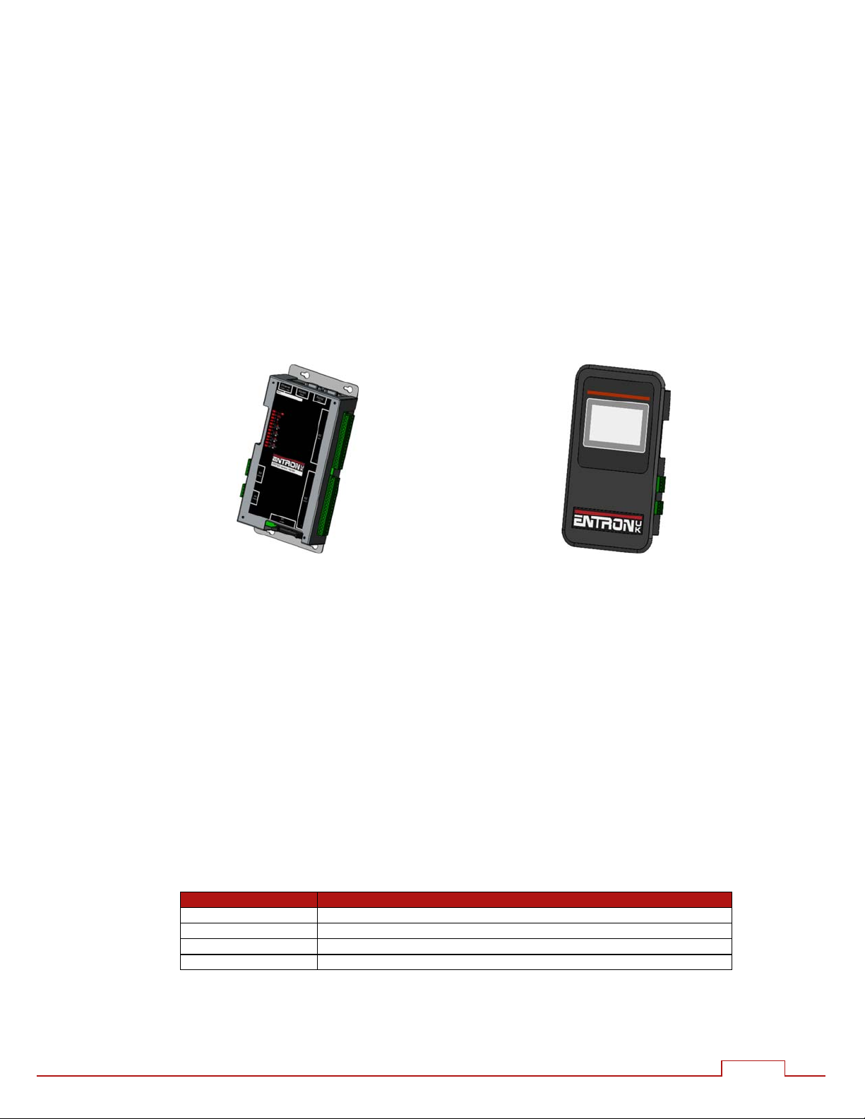
The controller is available in two formats:
EN7000: welding control with pre-heat, main heat and post-heat intervals, force
profile, multi-gun, multi-air valve, multi electrode manager and expansion port.
Gear-plate (flat plate) mounted.
EN7000-TS: as EN7000, plus built-in touch screen display.
Front panel mounted.
EN7000 EN7000-TS
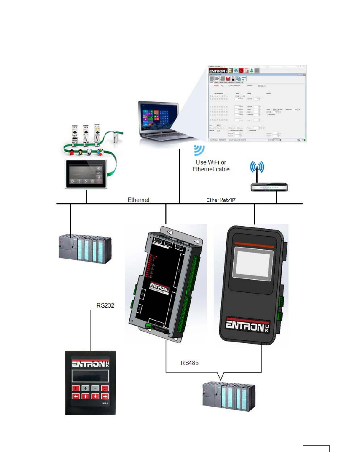
Multiple communication and control options are supported by a number of programming
methods. The Ethernet port supports simultaneous programming and control connection via a
single physical cable. EN7000v2 and EN7000v2-TS include integrated EtherNet/IP. For EN7000 and
EN7000-TS, EtherNet/IP can be provided via an optional plug-in adapter board.
Short-circuit proof outputs and a guided-contact pilot relay provides enhanced safety.
Connection to the power system is via a single ribbon cable. Analog inputs and outputs can be
used to drive a proportional air regulator valve for force control.
Operation in Standard mode provides a basic set of features for simple applications. Extended
mode adds advanced features for more demanding applications. Choose between Standard
or Extended features (See Configuration section). EN7000 must be restarted after changing this
setting.
1.1. Part numbers
Model Part number
EN7000 01-07-03
EN7000-TS 01-07-04
EN7000v2 01-27-03
EN7000v2-TS 01-27-04

EN7000 User Guide
8
1.2. Features
Model
EN7000 EN7000-TS
NetFlash
programming
WSP3 programming
Built-in programmer
1
Panel mounting
Gear-plate mounting
Ethernet
2
EtherNet/IP
3
RS232
RS485
MODBUS TCP/IP
MODBUS RTU
Analogue inputs
4
1 1
Analogue outputs
4
1 1
Discrete inputs 16 16
Discrete outputs
5
16 16
Weld programmes 256 256
Pre-heat
Main heat
Post-heat
6
Slope
Constant current
Power factor adjust
Cascade/Mux
6
8 8
Multi air valve
6, 7
8 8
Aux valves 7 7
Force profile
6
Electrodes/SCRs
6
8 8
Real-time clock
Data log (spot welds) 6000 6000
Expansion slot
Analog control
6
1
Colour touch-screen display
2
Two simultaneous connections
3
Standard on v2 models, otherwise requires plug-in adapter board.
4
0 to 10 V
5
24 V dc, short-circuit proof, monitored
6
Extended feature
7
Guided contact safety relay, monitored
The symbol is used throughout this manual to indicate
that the feature is available when the configuration parameter
Features is set to extended.
Extended

EN7000 User Guide
9
1.3. Weld schedule parameters
EN7000/EN7000-TS
Presqueeze
Squeeze
Pre-heat
Cool1
Upslope
Main heat
Cool2
Downslope
Pulses
Post-heat
1
Hold
Off
WAV selection
1
Aux valve control
Retract/Hi-lift
Electrode selection
1
Force profile
1
SCR selection
1
Current monitor
Retry
1
Conduction monitor
1
Force monitor
Spot weld
Roll-spot weld
1
Seam weld
1
1
Extended feature
The extended features option can be enabled for greater flexibility or
more demanding applications.
EN7000 User Guide
10
1.4. Programming options
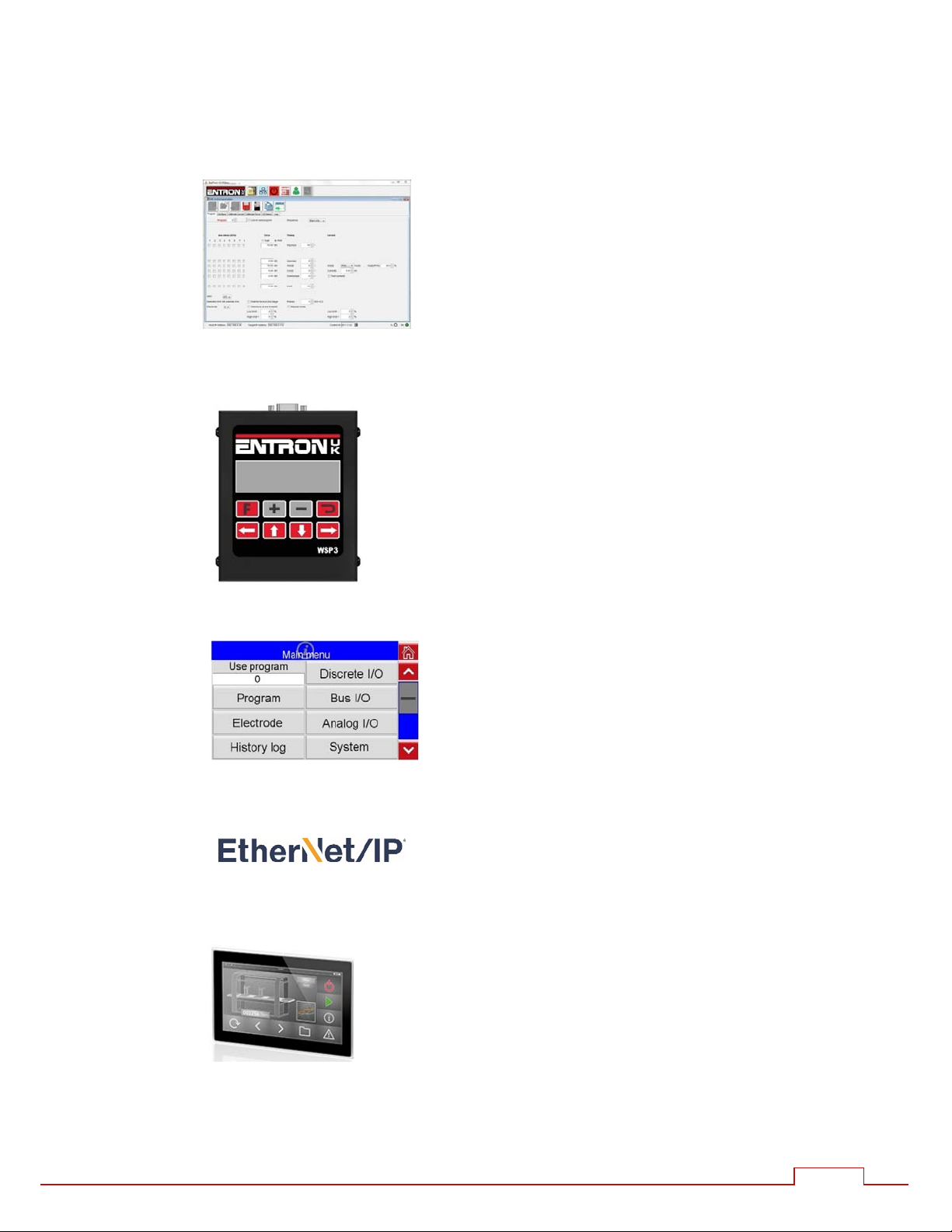
1.4.1. NetFlash
This PC-compatible program displays and allows
editing of all welding parameters and status
information.
In addition to programming, NetFlash provides
backup/restore functions for control data, live data
logging to a file and a utility for updating the firmware
in the EN7000.
1.4.2. WSP3 Pendant
EN7000s work with the same WSP3 pendant that is used
with iPAK, iPAK2 and WS2003. Access to all parameters
is provided, plus diagnostic indication.
1.4.3. Built-in touch screen
EN7000-TS has a touch screen panel which provides
easy access to all parameters and indications.
1.4.4. EtherNet/IP
On v2 models, EtherNet/IP is integrated as standard.
On other models, an optional adapter card can be
fitted to the expansion port, providing full data access
via the EtherNet/IP protocol.
1.4.5. Modbus
A PLC or HMI MODBUS master can be used to program,
control and monitor EN7000s. All parameters are
directly mapped to MODBUS registers for easy access.
Both MODBUS-TCP/IP (Ethernet) and MODBUS-RTU
(RS485) protocols are supported.
EN7000 User Guide
11
1.5. Communications
EN7000 User Guide
12
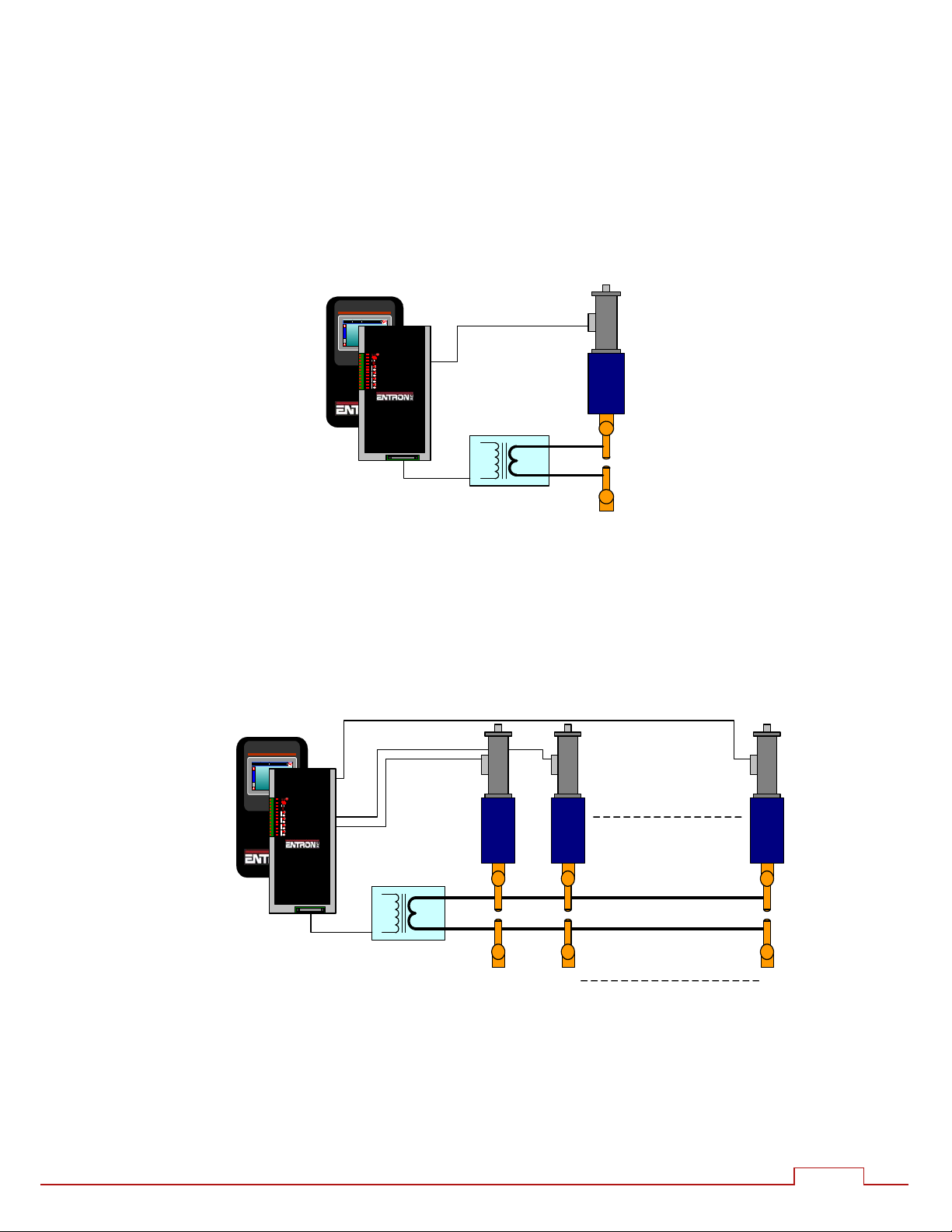
1.6. Applications
Standard machines, portable/manual guns, robot guns, multi-welders and seam welders.
Standard machine.
Multi-head machine. Up to eight cylinders. Cascade or independent firing.
Program 1
I1 = 17.0 kA H1 = 23.5% PHA
PSQ = 0 ~ SQZ = 10 ~
W1 = 12 ~ C1 = 0 ~
W2 = 12 ~ C2 = 0 ~
HLD = 10 ~
Edit Program
12.5 kA Prog 01 Low current W2
BF701 V1.01
Program 1
I1 = 17. 0 kA H1 = 23.5% PHA
PSQ = 0 ~ SQZ = 10 ~
W1 = 12 ~ C1 = 0 ~
W2 = 12 ~ C2 = 0 ~
HLD = 1 0 ~
Edit Pro gr am
12.5 kA Prog 01 Low cu rrent W 2
BF701 V1.01
12 8

EN7000 User Guide
13
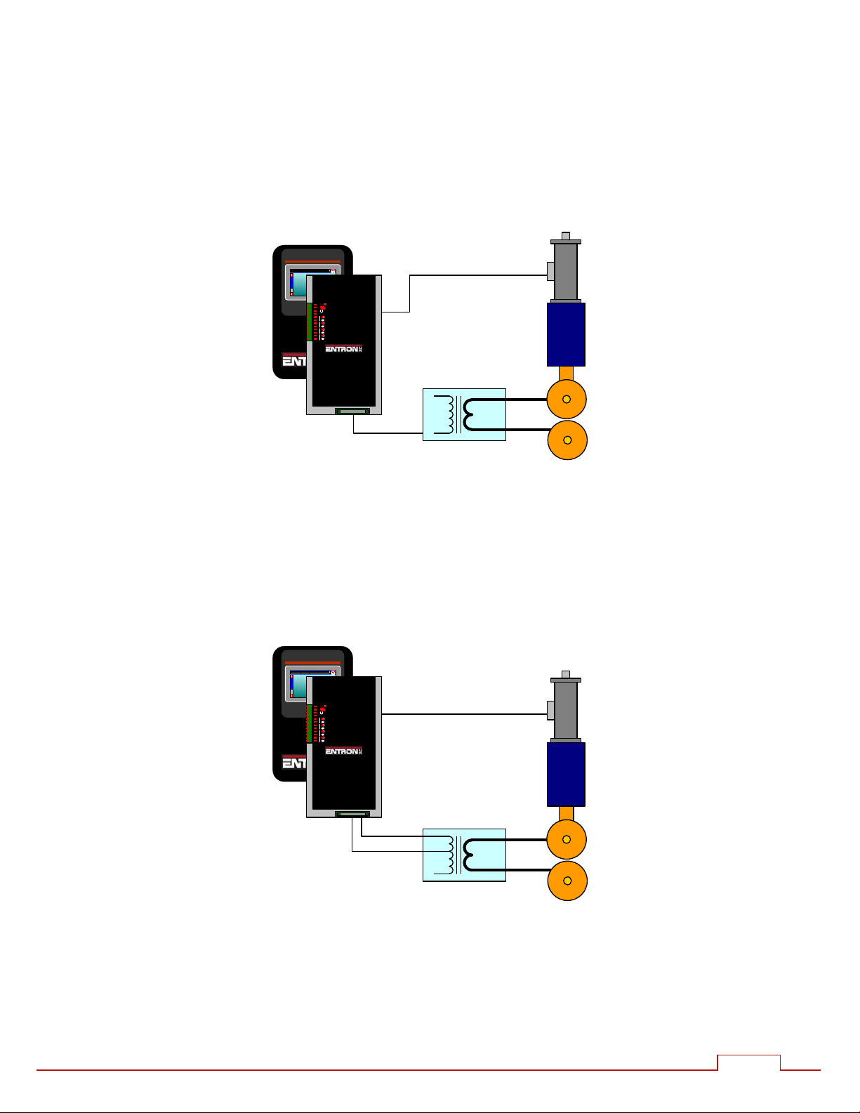
Multi-welder. Up to 8 transformers and cylinders. Cascade or independent firing.
Program 1
I1 = 17.0 kA H1 = 23.5% PHA
PSQ = 0 ~ S QZ = 10 ~
W1 = 12 ~ C1 = 0 ~
W2 = 12 ~ C2 = 0 ~
HLD = 10 ~
Edit Progr am
12.5 kA Prog 01 Low current W2
BF701 V1.01
1
2
8
8
2
1
EN7000 User Guide
14
Program 1
I1 = 17.0 kA H1 = 23.5% PHA
PSQ = 0 ~ SQZ = 10 ~
W1 = 12 ~ C1 = 0 ~
W2 = 12 ~ C2 = 0 ~
HLD = 10 ~
Edit Pr ogra m
12.5 kA Prog 01 Low current W2
BF701 V1.01
Seam welder with one transformer.
Program 1
I1 = 17.0 kA H1 = 23.5% PHA
PSQ = 0 ~ SQZ = 10 ~
W1 = 12 ~ C1 = 0 ~
W2 = 12 ~ C2 = 0 ~
HLD = 10 ~
Edit Pr ogra m
12.5 kA Pr og 01 Low current W2
BF701 V1.01
Seam welder with a multi-tap transformer.

EN7000 User Guide
15
2. Weld Control
EN7000 controls the weld sequence by using the I/O in conjunction with the welding parameters. The
parameters are stored in programs so that different materials and machine sequences can be used.
There are 256 weld programs.
2.1. Sequence timing
Parameter Units Range Description
Presqueeze cycles 0 - 99 The time for the electrodes to close onto the work piece.
Squeeze cycles 0 - 99 The time between the initial application of the electrode
force and the first application of welding current
Pre-heat
1
cycles 0 - 99 The pre-heat welding current is applied
Cool1
1
cycles 0 - 99 The material is allowed to cool with electrode force
applied
Upslope cycles 0 - 99 Welding current is increased during this time
Main heat cycles 0 - 99 The main welding current is applied
Cool2
2
cycles 0 - 99 The material is allowed to cool with electrode force
applied
Downslope cycles 0 - 99 Welding current is decreased during this time
Post-heat
3
cycles 0 - 99 The post-heat welding current is applied
Hold cycles 0 - 99 Electrode force continues after the welding current has
finished
Off
4
cycles 0 - 99 Electrode force is released until the next sequence begins
1
Pre-heat program option must be enabled to use this feature
2
Pulsations program option must be greater than 1 to use this feature
3
Post-heat program option must be enabled to use this extended feature
4
Repeat mode or Roll-spot program option must be enabled to use this feature
Upslope can be used on hard, irregular shaped, oxidized and
aluminium materials
Downslope can be used to reduce marking and embrittlement
Pre-heat and Post-heat can be used on hard or heat resistant
metals

EN7000 User Guide
16
2.2. Program options
Each weld program has a number of optional features.
Parameter Range Description
Pre-heat on/off Enables or disables the Pre-heat parameters
Post-heat
2
on/off Enables or disables the Post-heat parameters
Pulsations 1 - 99 The number of times the Main heat – Cool2 interval is repeated
Link
2
on/off The next welding program will be started automatically if the
input signals are maintained
Repeat on/off The welding program will be repeated if the input signals are
maintained
Force profile on/off Use multiple force values during the weld
Inhibit
1
on/off An inhibited program will not run
Retry
2
On/off Weld schedule will re-run if low main current detected – spot
weld only.
C-Monitor shunt
2
on/off The measured conduction will be checked against the C-Monitor
shunt limit
C-Monitor wear
2
on/off The measured conduction will be checked against the C-Monitor
wear limit
1
If an inhibited program is not linked then attempting to run it will produce an error message. If
the program is linked, then the program will be skipped and the next linked program will run.
This feature may be used to temporarily disable a program in a cascade.
2
Extended mode must be set in Configuration to use
this feature
Pulsations can be used to temper the material, control nugget
growth and reduce electrode wear.
The START signal must be maintained for the full duration of the
sequence if pulsations are set to 10 or more, otherwise the
sequence will terminate after 10 pulses.

EN7000 User Guide
17
2.3. Current control
The weld programs contain the following current control parameters.
Parameter Units Range Description
Pre-mode
1
PHA/CCR Operating mode of the Pre-heat interval
Pre-heat
1
% 0.0 – 99.9 The % heat used during the Pre-heat interval in PHA
mode
Pre-current
1
kA 0 – 500 The current used during the Pre-heat interval in CCR
mode. Set point for monitoring.
Main mode PHA/CCR Operating mode of the Main heat interval
Main heat % 0.0 – 99.9 The % heat used during the Main heat interval in PHA
mode
Main current kA 0 – 500 The current used during the Main heat interval in CCR
mode. Set point for monitoring.
Post mode
2
PHA/CCR Operating mode of the Post-heat interval
Post heat
2
% 0.0 – 99.9 The % heat used during the Post-heat interval in PHA
mode
Post current
2
kA 0 – 500 The current used during the Post-heat interval in CCR
mode. Set point for monitoring.
Test current on/off Each current can be tested between limits
High limit % 0 - 99 Current high limit
Low limit % 0 - 99 Current low limit
3-Phase trim
3
% +/- 99 Balances the current in each phase
1
Pre-heat program option must be enabled to use this feature
2
Post-heat program option must be enabled to use this extended feature.
3
3-phase configuration must be selected to use this feature
PHA (Phase Angle) mode. The current and heat parameters are independently adjustable. No
current regulation takes place.
CCR (Constant Current) mode.
The current parameter is adjustable but the heat is
automatically determined by the EN7000 to regulate the current.
EN7000 User Guide
18
2.4. Timing diagrams
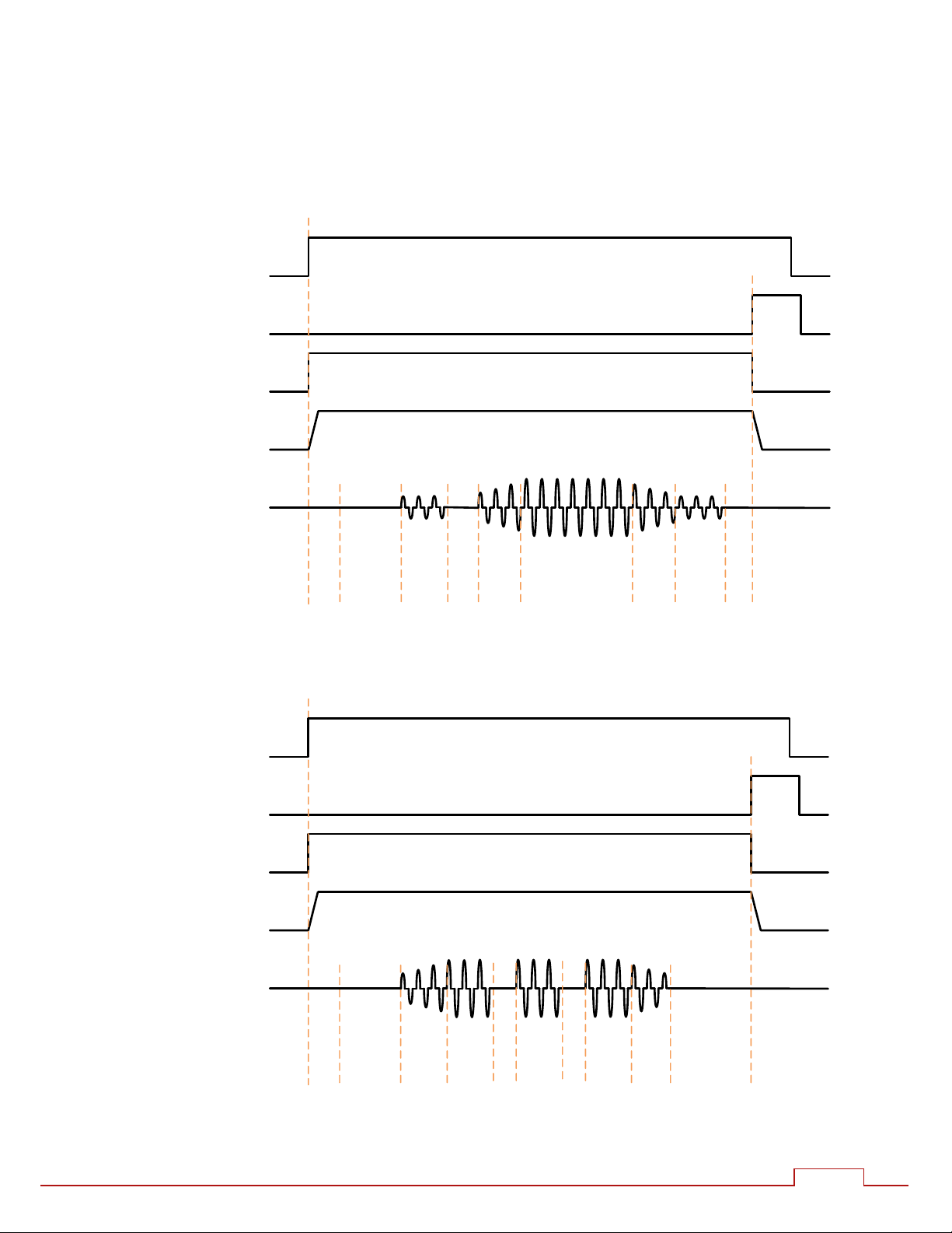
2.4.1. Spot weld
Pre-heat = 0, Cool1 = 0, Upslope = 0, Downslope = 0, Post-heat = 0, Pulsations = 1, Force
profile = Off.
EOSO/P
WAVO/P
ForceO/P
Current
Presqueeze
Squeeze
Mainheat
Hold
Cool1
Pre‐heat
Upslope
Downslope
STARTI/P
Post‐heat
2.4.2. Spot pulsation
Pre-heat = 0, Cool1 = 0, Post-heat = 0, Pulsations = 3, Force profile = off.
EOSO/P
WAVO/P
ForceO/P
Current
Presqueeze
Squeeze
Mainheat
Hold
Upslope
Downslope
STARTI/P
Mainheat
Mainheat
Cool2
Cool2
EN7000 User Guide
19
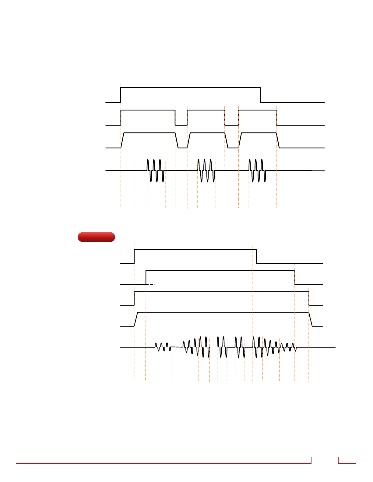
2.4.3. Spot repeat
Pre-heat = 0, Cool1 = 0, Upslope = 0, Downslope = 0, Post-heat = 0, Pulsations = 1, Force
profile = Off.
WAVO/P
ForceO/P
Current
Presqueeze
Squeeze
Hold
STARTI/P
Mainheat
Off
Hold
Off
Squeeze
Hold
Squeeze
Mainheat
Mainheat
2.4.4. Seam
MOTORO/P
WAVO/P
ForceO/P
Current
Presqueeze
Squeeze
Mainheat
Hold
Cool1
Pre‐heat
Upslope
Downslope
STARTI/P
Post‐heat
Mainheat
Mainheat
Mainheat
Cool2
Cool2
Cool2
The position of rising edge of the MOTOR output depends on the selection of the
Second Stage configuration parameter.
Continuous seam operation is obtained when Cool 2 = 0.
A spot weld (in Seam mode) can be produced by using the pre-heat with
Main heat = 0.
Extended
Other manuals for EN7000
1
This manual suits for next models
7
Table of contents
Other Entron Welding Accessories manuals


