Operation Manual
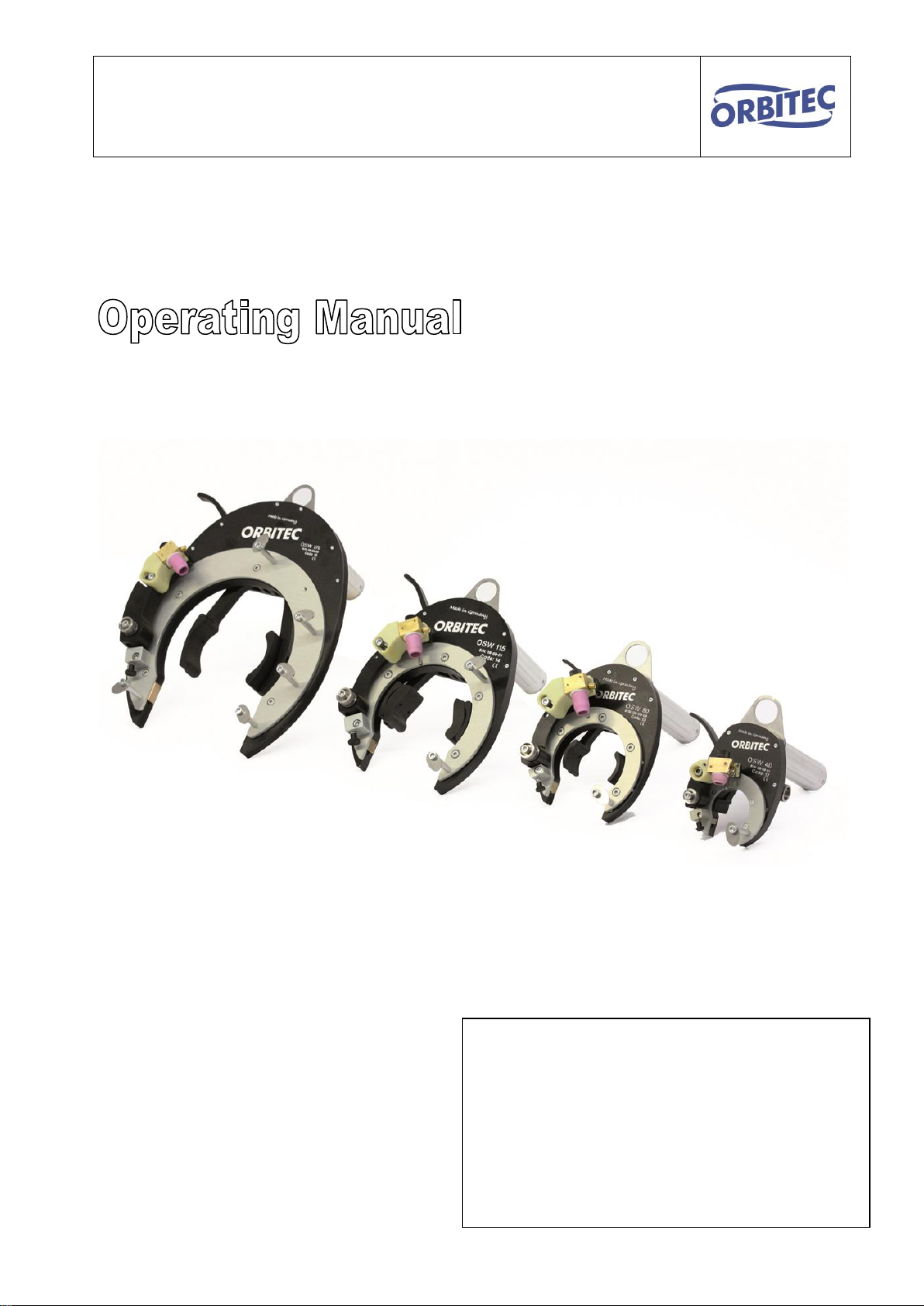
"Open Frame Welding Head OSW Series"
9
4. Functional principles of the open frame weld head
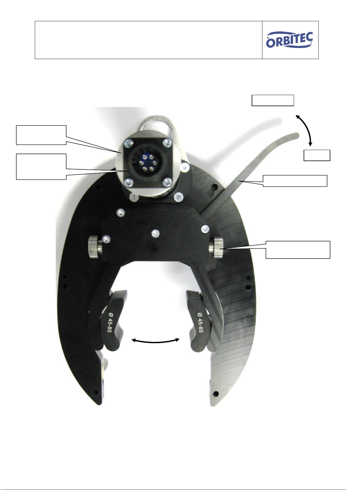
In the OSW welding tongs, the torch ring onto which the TIG torch is mounted, as well as the body of the
tongs, are open. The tool carrier is driven by several gear wheels. This ensures a continuous turning move-
ment in all welding positions.
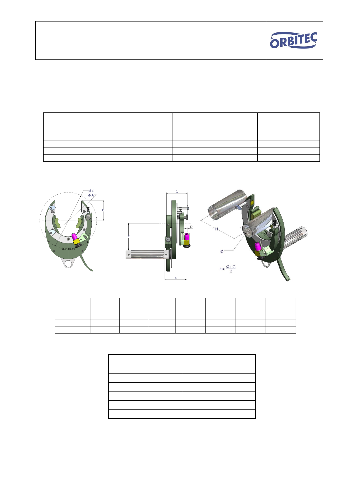
The head is adjusted to the diameter of the pipe using the adjustment screws of the quick-action clamping
lever.
It can be fastened immediately onto the tube over the weld joint.
The torch arm is loaded with a pressure spring at its point of rotation. After releasing the torch arm lock, the
torch is pressed onto the pipe. The torch arm with the TIG torch can be adjusted over the weld joint in three
dimensions.
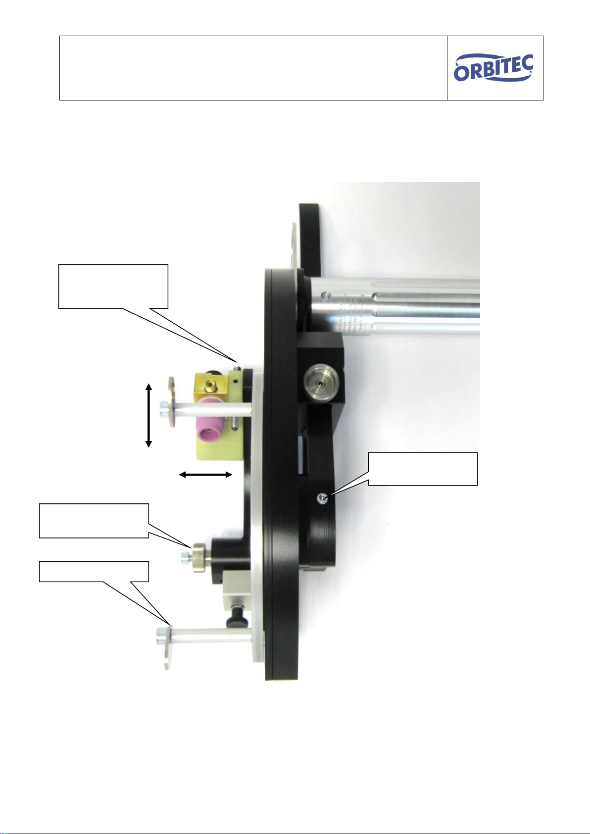
The arc distance is set via the torch height adjustment using a hexagon key and kept constant. The surface of
the pipe is continuously sensed.
The knurled screw provides fine adjustment to alter the side distance of the torch to the weld joint. The angle
of the torch head to the weld joint is continuously adjustable via the locking screws of the insulator and the
torch body Adjustment of the head for welding fillet welds is thus accomplished with little effort. For fillet welds,
torch holder which can be turned inwards and possibly also a "ceramic fillet weld nozzle" is required.
Welding with cold wire is possible by fitting the wire guide and the feed nozzle. The feed nozzle is attached to
the torch boy with two knurled screws It is adjustable. The wire guide hose is placed on the hose package
holder together with the hose package of the TIG torch before welding.
For further information see the Orbifeed operation manual.