aquatherm 50336 User manual

BEDIENUNGSANLEITUNG
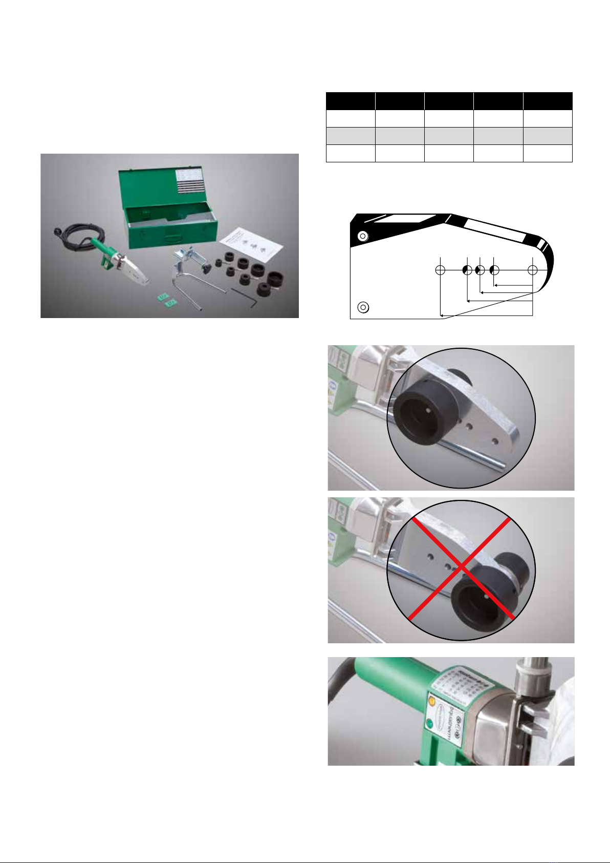
aquatherm Handschweißgeräte Art.-Nr. 50336, 50337, 50341
Für die Verarbeitung von
aquatherm green pipe, aquatherm blue pipe, aquatherm lilac pipe,
aquatherm red pipe und aquatherm ti
Rohrleitungssystemen der Dimensionen 16-125 mm
Deutsch English Italiano Español
SICHERHEITSVORSCHRIFTEN
1. Dieses Gerät darf ausschließlich unter Beachtung der vorliegenden
Anleitung benutzt werden. Jeder andere Einsatz gilt als unsachgemäß
und ist untersagt, da hierdurch Verletzungsgefahr für den Anwender
oder Dritte besteht und Schäden am Gerät oder anderen Gegenstän-
den verursacht werden können.
2. Die Gesetzesvorschriften in bezug auf Arbeitssicherheit und Ge-
sundheitsschutz sind strikt zu befolgen. Die Geräte dürfen nicht von
Kindern oder Personen mit reduzierten körperlichen, sinnlichen oder
geistigen Fähigkeiten benutzt werden.
3. Das Bedienungspersonal der Maschine muss hierfür geschult sein
und über die einschlägigen Arbeitsschutzvorschriften unterrichtet sein.
4. Aufgrund der technischen Eigenschaften und des vorgesehenen Ein-
satz der Maschine, müssen folgende Vorschriften strikt befolgt werden:
4.1. Netzspannung:
Die elektrischen Kenndaten von Maschine und bauseitiger Elektro-
anlage müssen übereinstimmen. Dieses Gerät darf nicht an Strom-
quellen mit Stromschwankungen (Über-/Unterstrom) angeschlossen
werden. Es muss an ein sicheres Stromnetz oder einen Generator
mit Spannungsstabilisator angeschlossen werden. Die Steckdose, an
welche die Schweißmaschine angeschlossen wird, muss durch einen
hochsensiblen Fehlerstrom-Schutzschalter (IΔ=30 mA) und Erdung ge-
schützt sein.
4.2. Elektrizität:
Aufgrund der Eigenschaften von elektrischer Energie
besteht beim Einsatz von elektrischen Geräten trotz
normgerechter Projektierung und Bauweise bzw. trotz Sicherheits-
vorkehrungen Gefahr für die Sicherheit, d.h. Stromschlaggefahr.
Maschine und Kabel dürfen weder Regen noch chemischen Stoffen
oder mechanischen Krafteinwirkungen (z.B. Überfahren der Kabel mit
Fahrzeugen) ausgesetzt werden. Desweiteren dürfen nur einwandfrei
trockene Rohrleitungen und Fittings verschweißt werden. Das Gerät
nicht mit nassen Händen oder in nasser Umgebung in Betrieb nehmen.
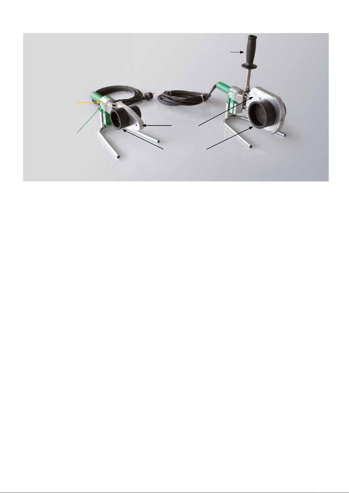
4.3. Verbrennungsgefahr:
Heizelement, Metallteile der Maschine und
die zu verschweißenden Kunststoffteile
erreichen hohe Temperaturen und dürfen während der Erwärmung,
Schweißung und Abkühlung nicht berührt werden. Beim Umgang mit
der Maschine ist größte Vorsicht geboten. Zur Vermeidung von Ver-
brennungen müssen stets Wärmeschutzhandschuhe und geeignete
Arbeitskleidung getragen werden.
4.4. Arbeitsplatz:
Der Arbeitsbereich muss für Unbefugte unzugänglich sein. Er muss
sauber, ordentlich, belüftet und gut beleuchtet sein. Es dürfen keine
Gase, Dämpfe, brennbaren Materialien wie Lösungsmittel, Öl, Lacke
usw. zugegen sein. Falls derartige Stoffe in den Aktionsbereich des
Heizelements geraten, besteht Brandgefahr. Nicht hitzebeständige
Gegenstände oder Materialien von der Schweißmaschine fernhalten.
Beim Schweißen in engen Räumlichkeiten ist zur Überwachung der
Arbeiten eine zweite Person erforderlich, die dem Bediener bei Bedarf
helfen kann.
4.5. Prüfungen und Reparaturen:
Vor jedem Maschineneinsatz die Unversehrtheit ihrer Komponenten
überprüfen. Verschlissene Kabel oder Komponenten umgehend durch
neue ersetzen. Reparaturen dürfen ausschließlich durch Fachpersonal
und unter Verwendung von Original- Ersatzteile ausgeführt werden.
Bei der Demontage der Maschine besteht Stromschlaggefahr. Am Ge-
rät dürfen keine Änderungen vorgenommen werden.
4.6. Anwesenheit des Bedieners während der Arbeit:
Das Gerät darf während der Schweißung bzw. der Erwärmung nicht
unbeaufsichtigt gelassen werden.
4.7. Nur chemisch träge Rohrleitungen verwenden:
Es dürfen keine Rohrleitungen verschweißt werden, die Substanzen
enthalten, bzw. enthalten haben, die in Verbindung mit Hitze explosive
oder für den Menschen gefährliche Gase erzeugen.
4.8. Halterung:
Die Schweißmaschine darf ausschließlich auf den hierfür vorgesehe-
nen Halterungen (Gabel, Werkbankhalterung) befestigt werden.
4.9. Kabel vorsichtig behandeln:
Stecker, Steckdosen, Verbinder nicht am Versorgungskabel abziehen
und letzteres nicht für den Maschinentransport verwenden.
4.10. Abschließend:
Nach der Arbeit den Maschinenstecker aus der Steckdose herausziehen.
5. Der Einsatz der Maschine an Orten mit Brandgefahr oder in Ex-
Bereichen ist untersagt. An derartigen Orten müssen eigens hierfür
geplante und gefertigte Maschinen verwendet werden.
5.1. Es ist sicherzustellen, dass das Netzkabel und alle anderen wär-
meempfindlichen Komponenten nicht mit dem Schweißspiegel in Kon-
takt kommen. Nach Beendigung der Schweißarbeiten und bevor das
Gerät zurück in den Koffer gelegt wird ist sicherzustellen, dass alle
Oberflächen genügend kalt sind, damit Brände vermieden werden.
6. Bei unsachgemäßem Gebrauch des Geräts übernehmen weder der
Hersteller noch der Verkäufer Haftung für Personen- oder Sachschäden.
aquatherm GmbH • Biggen 5 • 57439 Attendorn • www.aquatherm.de

E D C B A
85
60,00
50
35
WICHTIG!
Es dürfen nur original aquatherm-Schweißgeräte und -werkzeuge,
bzw. durch aquatherm freigegebene Geräte und Werkzeuge, verwendet
werden.
2. Schweißwerkzeuge im kalten Zustand mit der Hand aufschrauben
und handfest anziehen.
3. Vor der Fusion von Verteilerblöcken, bei denen zwei Anschlüsse
gleichzeitig geschweißt werden, sind die Schweißwerkzeuge in
die entsprechenden Löcher des Heizschwerts, wie nebenstehend
in Tabelle A und Zeichnung B beschrieben, zu platzieren.
4. Die Schweißwerkzeuge müssen frei von Verunreinigungen sein und
vor der Montage auf Sauberkeit geprüft werden. Falls erforderlich
sind Heizbuchse und Heizdorn mit einem nicht fasernden, groben
Papiertuch und evtl. mit Spiritus zu reinigen.
5. Schweißwerkzeuge immer so montieren, dass die Oberfläche nicht
über den Rand des Heizschwerts ragt. Schweißwerkzeuge ab Ø 40
mm sind immer an den hinteren Bohrungen des Heizschwertes zu
befestigen.
6. Schweißgerät an die Stromversorgung anschließen. Die grüne Zu-
standsanzeige leuchtet konstant, sobald das Gerät mit dem Strom-
netz verbunden ist.
Kontrollieren, ob die Betriebsleuchte brennt. Diese leuchtet konstant
während der Aufheizphase und blinkt nach Erreichen der Schweiß-
temperatur
Je nach Umgebungstemperatur dauert das Aufheizen des Schweiß-
schwertes zwischen 10 und 30 Minuten.
TEIL A: MONTAGE DER SCHWEISSWERKZEUGE
Art.-Nr. Durchgang Lochplatz Abgänge Lochplatz
30115 Ø 25 mm A + E Ø 20 mm A + C
85123 Ø 20 mm A + B Ø 16 mm A + C
85124 Ø 20 mm A + B Ø 16 mm A + C
A
B
FALSCH
RICHTIG
Betriebsanzeige (gelb) und Zustandsanzeige (grün)

Schweißwerk-
zeuge
Heizschwert
Handgriff
Betriebsanzeige (gelb)
leuchtet konstant
während der Aufheiz-
phase und blinkt nach
Erreichen der Schweiß-
temperatur
Zustandsanzeige (grün)
leuchtet konstant, sobald das Gerät
mit dem Stromnetz verbunden ist.
TEIL A: AUFHEIZPHASE/HANDHABUNG
Aufheizphase
7. Während der Aufheizphase ist die Schraube der Schweißwerkzeuge
kräftig anzuziehen.
Dabei ist darauf zu achten, dass die Aufsätze vollflächig am Heiz-
schwert aufliegen. Es dürfen keine Zangen oder andere ungeeignete
Werkzeuge verwendet werden, damit die Beschichtung der Schweiß-
werkzeuge nicht beschädigt wird.
8. Die erforderliche Schweißtemperatur für die Verarbeitung der aqua-
therm PP-R Systeme beträgt 260 °C.Gemäß DVS-Schweißrichtlinie
ist die Schweißtemperatur vor Schweißbeginn am Werkzeug zu
kontrollieren.
Die Temperaturkontrolle erfolgt mit einem schnellanzeigenden Ober-
flächentemperaturmessgerät.
ACHTUNG:
Erste Schweißung 5 Minuten nach Erreichen der Schweißtemperatur!
Handhabung
9. Bei Werkzeugwechsel an einem aufgeheizten Gerät, ist nach der
Aufheizdauer erneut die Kontrolle der Einsatztemperatur an dem
neuen Werkzeug erforderlich.
10. Wenn das Gerät, während längerer Pausen, ausgeschaltet wird,
muss der Aufheizvorgang (ab Punkt 6) erneut durchgeführt werden.
11. Nach Beendigung der Schweißarbeiten Gerät ausschalten und ab-
kühlen lassen. Das Schweißgerät niemals mit Wasser abkühlen,
da sonst die Thermowiderstände zerstört werden.
12. aquatherm-Schweißgeräte und -Schweißwerkzeuge sind vor Ver-
unreinigungen zu schützen. Festgebrannte Partikel können zu einer
fehlerhaften Fusion führen.
Die Werkzeuge können mit aquatherm-Reinigungstüchern, Art.-Nr.
50193, gereinigt werden. Die Schweißwerkzeuge sind stets trocken
zu halten.
13. Das Gerät nach Durchführung einer Schweißung nicht auf die
teflonbeschichteten Werkzeuge legen, sondern in den mitgeliefer-
ten Ständer abstellen.
14. Beschädigte und verunreinigte Schweißwerkzeuge müssen un-
bedingt ersetzt werden, da nur einwandfreie Verarbeitungswerk-
zeuge einwandfreie Fusionsverbindungen garantieren.
15. Defekte Geräte niemals öffnen oder selbst reparieren. In diesem
Fall das Gerät zur Reparatur ins Werk senden.
16. Die Einsatztemperatur der aquatherm-Schweißgeräte regelmäßig
mit geeigneten Messgeräten überprüfen, bzw. überprüfen lassen.

TEIL A: RICHTLINIEN
Richtlinien
17. Für die Handhabung von Schweißmaschinen sind die Allgemeinen
Arbeitsschutz- und Unfallverhütungsvorschriften zu beachten. Ins-
besondere gelten die Richtlinien der Berufsgenossenschaft der Che-
mischen Industrie für Maschinen zur Be- und Verarbeitung von Kunst-
stoffen (Kapitel: „Schweißmaschinen und Schweißeinrichtungen“).
18. Für die Handhabung der aquatherm-Schweißgerätemaschinen und
-werkzeuge gelten weiterhin die Allgemeinen Richtlinien DVS 2208
Teil 1.
TEIL B: ÜBERPRÜFUNG DER GERÄTE
UND WERKZEUGE
1. Es muss geprüft werden, ob die eingesetzten Schweißgeräte und
-werkzeuge den Richtlinien „Fusionstechnik Teil A“ entsprechen.
2. Die verwendeten Geräte und Werkzeuge müssen die geforderte
Einsatztemperatur von 260 °C erreicht haben. Dies bedarf, gemäß
„Fusionstechnik Teil A, Punkt 8“ einer gesonderten Prüfung, welche
entsprechend der DVS-Schweißrichtlinie zwingend erforderlich ist:
Gemäß DVS-Schweißrichtlinie darf die Kontrolle der benötigten
Einsatztemperatur mit schnellanzeigenden Oberflächentemperatur-
Messgeräten durchgeführt werden.
Geeignete Messgeräte müssen eine Temperaturmesung bis 350 °C
ermöglichen und eine hohe Messgenauigkeit aufweisen.
HINWEIS
aquatherm empfiehlt das original aquatherm Temperatur-Messgerät
Art.-Nr. 50188
TEIL B: VORBEREITUNG FÜR DIE FUSION
3. Rohr rechtwinklig zur Rohrachse abtrennen. Es dürfen ausschließ-
lich aquatherm-Rohrabschneider bzw. geeignete Schneidewerk-
zeuge verwendet werden. Gegebenenfalls Rohr entgraten und
Schneidespäne entfernen.
4. Einschweißtiefe mit beiliegender Lehre und Graphitstift am Rohren-
de anzeichnen.
5. Gewünschte Position des Formteiles mit einer Markierung am Rohr
und/oder Fitting kennzeichnen. Die Hilfsmarkierungen am Formteil
und die durchlaufende Linie des Rohres können als Ausrichtungshil-
fe verwendet werden.
Temperaturmessung an der aquatherm- Stumpfschweißmaschine
Temperaturmessung am aquatherm- Handschweißgerät (800 W)
Temperaturmessung an der aquatherm-Schweißmaschine
Abschneiden des Rohres
Einzeichnen der Einschweißtiefe

TEIL B: ANWÄRMEN DER ELEMENTE
Rohr-
Außen-Ø Einschweiß-
tiefe Anwärmzeit Verarbei-
tungszeit Abkühlzeit
mm mm sec.
DVS sec.
AQE* sec. min.
16 13,0 5 8 4 2
20 14,5 5 8 4 2
25 16,0 7 11 4 2
32 18,0 8 12 6 4
40 20,5 12 18 6 4
50 23,5 18 27 6 4
63 27,5 24 36 8 6
75 30,0 30 45 8 8
90 33,0 40 60 8 8
110 37,0 50 75 10 8
125 40,0 60 90 10 8
6. Rohrende, ohne zu drehen, bis zur angezeichneten Einschweißtiefe
in die Heizbuchse schieben und gleichzeitig das Formteil, ohne zu
drehen, bis zum Anschlag auf den Heizdorn schieben.
Die Anwärmzeit gemäß untenstehender Tabelle ist unbedingt einzuhalten!
Rohre und Formteile der Dimensionen Ø 75-125 mm dürfen grundsätz-
lich nur mit dem Schweißgerät Art.-Nr. 50341 (oder der Schweißma-
schine Art.-Nr. 50148) verarbeitet werden.
ACHTUNG:
Die Anwärmzeit beginnt grundsätzlich erst, wenn die Einschweißtiefe
in der Heizbuchse bzw. der Anschlag auf dem Heizdorn erreicht ist.
7. Nach der vorgeschriebenen Anwärmzeit, Rohr und Formteil zügig
von den Schweißwerkzeugen abziehen und sofort, ohne zu drehen,
gerade zusammenschieben, bis die angezeichnete Einschweißtiefe
durch die entstandene Wulst des Formteiles abgedeckt ist.
ACHTUNG:
Das Rohr darf nicht zu tief in das Formteil eingeschoben werden, da
dies sonst zu Verengungen, im Extremfall zu Verschlüssen des Rohres
führen kann.
8. Die zusammengefügten Elemente sind während der Verarbeitungs-
zeit zu fixieren.
In dieser Zeit kann die Verbindung korrigiert werden. Die Korrektur
beschränkt sich lediglich auf das Ausrichten von Rohr- und Formteil.
Das Drehen der Elemente ist nicht zulässig. Nach Ablauf der Verarbei-
tungszeit darf die Verbindung nicht mehr ausgerichtet werden.
9. Nach der Abkühlzeit kann die Werkstoffeinheit voll belastet werden.
Das Ergebnis der Verschmelzung von Rohr und Fitting ist eine unlösbare
Werkstoff-Einheit der Systemelemente: Beispiellose Verbindungstech-
nik mit Sicherheit auf Lebenszeit!
Maßgebende Daten für die Fusion
*In Anlehnung an die DVS 2207, Teil 11 sollten die Anwärmzeiten
(sec. AQT) bei Umgebungstemperaturen unter +5 °C verwendet
werden.
Dimension 160 - 630mm:
Diese Dimensionen werden im Stumpfschweißverfahren ver-
schweißt.
Es gelten die allgemeinen Richtlinien
für Heizelementschweißen gem. DVS 2207, Teil 11.
Fügen, Fixieren und …
… Ausrichten der Formteile.
Das Resultat: Eine unlösbare Verbindung!
Anwärmen der Formteile

1.1
1.2
1.3
1.4
1.5
TEIL B: UNIVERSAL-SCHÄLGERÄTE
Mit Hilfe der Universal-Schälgeräte können die Endstücke von aquatherm
OT (sauerstoffdicht), UV (UV-beständig) und MS (mehrschichtig Stabi)
geschält werden. Durch das gleichmäßige Abtragen der Außenschicht
des Rohres wird eine beliebige Verlängerung des Rohrsystems durch
E-Muffe oder Formteil möglich. Die Universal-Schälgeräte gibt es in
den Größen Ø20 – Ø125 mm (Art. Nr. 50479 – 50488). Der Schälvorgang
erfolgt entweder mechanisch oder von Hand. Für die mechanische
Verarbeitung werden zwei Mitnehmerplatten für die Rohrgrößen Ø20 –
Ø63 mm (Art. Nr. 50499) und Ø75 – Ø125 mm (Art. Nr. 50500) angeboten.
Um E-Muffen mechanisch zu verarbeiten wird der Schäler mit einem
Aufsatz (Art. Nr. 50489 – 50498) verlängert. Die Bohrmaschinen oder
Akkuschrauber sollten ein hohes Drehmoment haben.
1. ANLEITUNG FÜR DEN MECHANISCHEN SCHÄLVORGANG
1.1. Die Mitnehmerplatte wird mit dem 6-kant Bolzen in den Akku-
schrauber eingespannt.
1.2. DerSchälerwirdmitseinenPassschraubeninderzumDurchmesser
passende Nut der Mitnehmerplatte fixiert und im Uhrzeigersinn
gedreht, sodass der Schäler an der Mitnehmerplatte hält.
1.3. Das am Bohrfutter eingespannte Schälgerät wird über die Füh-
rung am Rohrende angesetzt.
1.4. Bei Rotation des Schälgerätes beginnt unter leichtem Druck
(Vorschub) der Schälvorgang in Axialrichtung. Der Schälvorgang ist
abgeschlossen, wenn die Mitnehmerplatte am Rohrende anschlägt.
1.5. Das Rohr kann jetzt per Muffenschweißverfahren verschweißt werden.
2. ANLEITUNG MECHANISCHER SCHÄLVORGANG FÜR
ELEKTROSCHWEISSMUFFEN
2.1. Die Verlängerung wird mit dem Schäler durch die aufeinan-
derliegenden Passschrägen zentriert und mit drei Innensechs-
kantschrauben befestigt.
2.2.Die Mitnehmerplatte wird mit dem 6-kant Bolzen in den Akkuschrau-
ber eingespannt und mit dem Schäler verbunden (siehe Bild 1.2).
2.3. Bei Rotation des Schälgerätes beginnt unter leichtem Druck
(Vorschub) der Schälvorgang in Axialrichtung. Der Schälvorgang ist
abgeschlossen wenn die Mitnehmerplatte am Rohrende anschlägt.
2.4. Das Schälwerkzeug wird vom Rohr abgezogen und das E-Muffen-
schweißverfahren kann beginnen.
3. SCHÄLANLEITUNG FÜR DIE HANDSCHÄLUNG
3.1. Für die Handschälung werden zwei Knebel am Schälgerät montiert.
3.2. Der Schäler wird auf das unbehandelte Rohr bis zum Anschlag
aufgeschoben.
3.3. Der Schäler wird so lange im Uhrzeigersinn gedreht, bis die ange-
zeichnete Schältiefe (siehe Tabelle unten) erreicht ist.
3.4. Ist der Schäler bis zur vorgegebenen/angezeichneten Schältiefe
(siehe Tabelle) vorgedrungen, wird der Schäler abgezogen und
das Muffenschweißen kann beginnen. Sollte die E-Muffe als
Schiebemuffe eingesetzt werden, muss die Schältiefe für E-
Muffenschweißen (siehe Tabelle) verdoppelt werden.

2.1 3.1
2.2 3.2
2.3 3.3
2.4 3.4
Passschräge
SCHÄLTIEFENTABELLE
MUFFEN- UND E-MUFFENSCHWEISSEN
Durchmesser Schältiefe
Muffenschweißen
Schältiefe E-
Muffenschweißen
ø 20 16 mm 39 mm
ø 25 20 mm 43 mm
ø 32 22 mm 45 mm
ø 40 25 mm 50 mm
ø 50 28 mm 56 mm
Durchmesser Schältiefe
Muffenschweißen
Schältiefe E-
Muffenschweißen
ø 63 32 mm 65 mm
ø 75 34 mm 69 mm
ø 90 37 mm 77 mm
ø 110 42 mm 85 mm
ø 125 44 mm 90 mm

TEIL C: EINSCHWEISSSATTEL
aquatherm-Einschweißsättel stehen für die Rohr-Außendurchmesser
40 - 630 mm zur Verfügung.
Einschweißsattel werden in folgenden Einsatzbereichen verwendet:
• Für nachträgliche Abzweiganschlüsse
• Im Verteilerbau
• Als Etagenabzweig in Steigleitungen
• Zur Aufnahme von Tauchhülsen, u.v.m.
1. Vor Beginn des Schweißvorgangs ist zu prüfen, ob die verwendeten
Geräte und Werkzeuge den Richtlinien Fusionstechnik Teil A ent-
sprechen.
2. Zuerst muss die Rohrwandung mit dem aquatherm Bohrer durch-
bohrt werden (Art.-Nr. 50940-50958).
3. WICHTIG!
Ausschließlich bei den blue pipe OT-Rohren Art.-Nr. 2170708-2170138
ist die Sauerstoffsperrschicht mit den in der nebenstehenden Tabelle
aufgeführten aquatherm Sattelfräsern zu entfernen. Der Sattelfräser
wird hierzu in die Bohrung steckt und mit leichtem Druck und geringer
Umdrehungsgeschwindigkeit 2 bis 3 mal zwischen den sich gegenüber-
liegenden Rohrseiten hin und her bewegt; bis die Sauerstoffsperr-
schicht vollflächig abgeschält ist.
Grat, Spähne und andere Verschmutzungen mit einem Entgrater oder
den aquatherm Reinigungstüchern entfernen. Die geschälte Fläche
nicht mehr berühren und vor neuer Verunreinigung schützen.
Bei Verwendung von Stabiverbund-Rohren ist das, an der Bohrung ver-
bliebene Aluminium mit den aquatherm-Anfasgeräten Art.- Nr. 50910-
50914 zu entfernen.
4. Das Schweißgerät/Einschweißsattelwerkzeug muss die gefor-
derte Einsatztemperatur von 260 °C erreicht haben (Prüfung gemäß
„Fusionstechnik Teil B Punkt 2“).
5. Die zu verschweißenden Flächen müssen sauber und trocken sein.
6. Der Anwärmstutzen des Einschweißsattelwerkzeuges ist in die
Bohrung der Rohrwandung zu stecken, bis das Werkzeug die Rohr-
Außenwand komplett erreicht. Anschließend wird der Stutzen des
Sattels in die Heizbuchse eingeschoben, bis die Sattelfläche die
Werkzeugwölbung erreicht. Die Anwärmzeit der Elemente beträgt
bei allen Dimensionen 30 Sekunden.
7. Nach Entfernen des Schweißgerätes wird der Stutzen des Sattels
zügig in das angewärmte Bohrloch eingeschoben. Der Sattel ist
dann exakt und ohne Drehen auf die angewärmte Rohraußenober-
fläche zu drücken. Der Einschweißsattel wird 15 sec. auf dem Rohr
fixiert.
Nach einer Abkühlzeit von 10 Minuten ist die Verbindung voll belastbar.
Das entsprechende Abzweigrohr wird in gewohnter Fusionstechnik in
die Muffe eingeschweißt.
Durch die Verschmelzung des Einschweißsattels mit der Rohraußen-
oberfläche und der Rohrwandung erreicht die Verbindung höchste
Stabilität. Die Alternative im Verteilerbau.
Durchbohren der Rohrwandung
Anwärmen der …
… zu verschweißenden Elemente
Fügen
Fertig!
Entfernen der Sauerstoffsperrschicht beim aquatherm blue pipe OT Rohr
Art.-Nr. Abmessung
50921 für Einschweißsättel ø 20 & 25 mm
50922 für Einschweißsättel ø 32 mm
50924 für Einschweißsättel ø 40 mm
50926 für Einschweißsättel ø 50 mm
50928 für Einschweißsättel ø 63 mm
Art.-Nr. Abmessung
50421 für Einschweißsättel ø 20 & 25 mm
50422 für Einschweißsattel ø 32 mm
50424 für Einschweißsattel ø 40 mm
50426 für Einschweißsattel ø 50 mm
50428 für Einschweißsattel ø 63 mm
aquatherm
Sattelfräser für
aquatherm
blue pipe ot
Rohre ø 50-125 mm
aquatherm
Sattelfräser für
aquatherm
blue pipe ot
Rohre Ø 160-250 mm

OPERATION AND MAINTENANCE MANUAL
aquatherm welding device Art.-No. 50336, 50337, 50341
Fusion for
aquatherm green pipe, aquatherm blue pipe, aquatherm lilac pipe,
aquatherm red pipe and aquatherm ti
pipesystems from 16 up to 125 mm
Deutsch English Italiano Español
SAFETY STANDARDS
1. This equipment must only be used in full compliance with the
instructions given in this manual. All other uses are to be considered
improper and forbidden. Improper use may cause injury to the machine
operator or third parties and/ or cause damage to the machine or other
objects.
2. All standards concerning health and safety in the workplace must be
implemented at all times. The devices must not be used by children or
persons with reduced physical, sensory or mental capabilities.
3. Before using the machine personnel must be properly trained in its
operation and in applicable accident-prevention regulations.
4. The components used in the construction of the machine and its
operating principles are such that special care should be taken to carry
out the following instructions:
4.1. Electric power supply:
Make sure the mains electricity supply is suitable for the machine.
Do not use an electricity supply which is subject to voltage surges
or drops. Use a guaranteed mains supply or power generators fitted
with voltage stabilizers. Make sure the machine’s power socket is
protected with a high sensitivity differential switch (IΔ=30 mA) and
that the machine has an earth connection.
4.2. Electricity:
Even if designed and manufactured in full accordance
with applicable standards and fitted with all the
required safety devices, electrically powered machinery
nonetheless poses a risk to safety due to the nature
of this type of energy (i.e. risk of electric shock). Do not expose
the machinery and its electrical cables to the rain, to chemicals,
to mechanical stress (e.g. vehicles driving across the cables). Use
perfectly dry pipes and connectors. Do not use the machine if your
hands are wet or the workplace is moist or damp.
4.3. Avoiding burns:
Do not touch the heating element, metal
components or plastic parts close to the
welding surface during heating, welding
or cooling, since the plate reaches very
high temperatures. Operate the machine with the utmost care. Wear
heatproof gloves and protective clothing suitable for preventing burns.
4.4. The workplace:
Make sure that unauthorized persons are unable to gain access to the
workplace. The workplace must be clean, tidy, properly ventilated and
well lit. There should not be any gases, fumes or flammable materials
present, such as solvents, oils, paints, etc. These may constitute a fire
risk if they come close to the heating element. Keep any objects or
materials susceptible to heat damage well away from the machine.
When working in tight, awkward places an external supervisor must
be present to provide assistance to the machine operator in case of
need.
4.5. Checks and repairs:
Before using the machine check that no components are damaged.
Replace cables or components as soon as they become worn. Repairs
must be carried out only by an expert or specially trained technician
using exclusively original spare parts. Dismantling the machine
involves a risk of electric shock. No alterations may be made to the
machine.
4.6. Presence of the operator at all times during operation:
The machine operator must not leave the machine while it is welding
or heating up.
4.7. Use pipes that are chemically inert: Do not carry out any welding
operations on pipes containing, or which may have contained,
substances which when heated generate explosive gases or other
gases dangerous to the human body.
4.8. Support: Position the welding machine using only the proper fork
or bench supports.
4.9. Take care with cables: Do not disconnect plugs, sockets or
connectors or move the machine by pulling on the electric cables.
4.10. Finally...: After work, remember to disconnect the welding
machine from the mains or supply socket.
4.11. The machine must not be used in areas where there is a risk of
explosion or fire. Only specially designed and manufactured machines
must be used in workplaces of this kind.
5.1.Ensure that the power cord and all other heat-sensitive components
do not come in contact with the welding device. After completion of
the welding process and before the machine is put back into the case,
make sure that all surfaces are cold enough so that fire can be avoided.
5. The manufacturer and dealer will not be liable for personal injury
or damage to property arising from the improper use of the machine.
6. WARNING
In the event of a fault of any kind during the guarantee period, send
the machine to the manufacturer or an authorized repair centre. Having
repair work carried out by personnel not authorized by aquatherm will
immediately invalidate the warranty
aquatherm GmbH • Biggen 5 • 57439 Attendorn • www.aquatherm.de

E D C B A
85
60,00
50
35
IMPORTANT!
Only use the original aquatherm welding devices and aquatherm
welding tools, except devices and tools which are especially
approved by aquatherm.
2. Assemble and tighten the cold welding tools manually.
3. Before fusing the distribution block, in which two connections are
fused simultaneously, the welding tools have to be placed into the
respective holes as described in the adjoing table A and drawing B.
4. All welding tools must be free from impurities. Check if they are
clean before assembling. If necessary clean the welding tools with
a non fibrous, coarse tissue and with methylated spirit.
Place the welding tools on the welding device so that there is full
surface contact between the welding tool and the heating plate.
Welding tools over Ø 40 mm must always be fitted to the rear
position of the heating plate.
Electric supply:
The power supply must coincide with the data on the type plate of
the welding device and must be protected according to the local
regulations. To avoide high power loss, the conductor cross-section
of the used extension cables must be selected according to the
power input of the welding devices.
6. Plug in the welding device. The green operating lamp glows
constantly, as soon as the device is conntected with the power
supply system.The temperature pilot lamp glows constantly while
the heat-up phase and blinks, when the welding temperature is
achieved.
Depending on the ambient temperature it takes 10-30 minutes to
heat up the heating plate.
PART A: MOUNTING OF THE TOOLS
Art.-No. Passage Hole Branch Hole
30115 Ø 25 mm A + E Ø 20 mm A + C
85123 Ø 20 mm A + B Ø 16 mm A + C
85124 Ø 20 mm A + B Ø 16 mm A + C
WRONG
RIGHT
A
B
Temperature pilot lamp (yellow) and operating lamp (green)

Part A: Heating up phase
7. During the heating up phase tighten the welding tools carefully with
the Allan key.
Take care that the tools completely contact the heating plate. Never
use pliers or any other unsuitable tools, as this will damage the coating
of the welding tools.
8. The temperature of 260° C is required for the welding of aquatherm
PP-R pipes.
Acc. to DVS-Welding Guidelines the temperature of the welding
device has to be checked at its tool before starting the welding
process.
This can be done with a fast indicating surface thermometer.
ATTENTION:
First welding - soonest 5 minutes after reaching of the welding
temperature. DVS 2207, Part 11.
Part A: Handling
9. A tool change on a heated device requires another check of the
welding temperature at the new tool (after its heating up).
10. If the device has been unplugged, e.g. during longer breaks, the
heating up process, has to be restarted (see item 6).
11. After use unplug the welding device and let it cool down. Water
must never be used to cool the welding device, as this would
destroy the heating resistances.
12. Protect aquatherm-welding devices and tools against impurities.
Burnt particles may lead to an incorrect fusion. The tools may be
cleaned with aquatherm cleaning cloths, Art.-No. 50193.
Always keep the welding tools dry.
13. After welding, do not lay the the device on the Teflon coated tool,
but put it down in the provided supporting stand.
14. For a perfect fusion, damaged or dirty welding tools must be
replaced, as only impeccable tools guarantee a perfect connection.
15. Never attempt to open or repair a defective device. Return the
defective device for repair.
16. Check the operating temperature of aquatherm-welding devices
regularly by means of suitable measuring instruments.
PART A: HEATING UP PHASE / HANDLING
Welding tools
Heating plate
Handle
Temperature pilot lamp
(yellow)
glows constantly while the
heat-up phase and blinks,
when the welding temperature
is achieved
Operating lamp
(green)
glows constantly, as soon as
the device is conntected with
the power supply system

Part A: Guidelines
17. For the correct handling of welding machines the following must
be observed:
General Regulations for Protection of Labour and Prevention of Ac-
cidents and particularly the Regulations of the Employers’ Liability
Insurance Asso-ciation of the Chemical Industry regarding Ma-
chines for the Processing of Plastics, chapter: „Welding Machines
and Welding Equipment“.
18. For the handling of aquatherm-welding machines, devices and
tools please observe General Regulations DVS 2208 Part 1 of the
German Association for Welding Engineering, Registered Society
(Deutscher Verband für Schweißtechnik e. V.).
Part B: Checking of devices and tools
1. Check, if the aquatherm-welding devices and tools comply with to
the guidelines “Fusion Part A”.
2. All used devices and tools must have reached the necessary
operating temperature of 260 °C. This requires acc. to “Fusion Part
A, item 8” a separate test, which is indispensable (DVS-Welding
Guidelines):
Suitable measuring instruments have to measure a temperature of up
to 350° C with a high accuracy.
NOTE:
aquatherm recommends the original aquatherm temperature measu-
ring device art.-no. 50188
PART B: PREPARATION FOR THE FUSION
3. Cut the pipe at right angles to the pipe axis. Only use aquatherm
pipe cutters or other suitable cutting pliers. Take care that the
pipe axis is free from burrs or cutting debris and remove where
necessary.
4. Mark the welding depth at the end of the pipe with the enclosed
pencil and template.
5. Mark the desired position of the fitting on the pipe and / or fitting.
The markings on the fitting and the uninterrupted line on the pipe
may be used as a guide.
PART A: GUIDELINES
PART B: CHECKING OF DEVICES AND TOOLS
Measurement of temperature at the aquatherm butt-welding machine
Measurement of temperature at the aquatherm manual welding device (800W)
Measurement of temperature at the aquatherm welding machine
Cutting of the pipe
Marking of the welding depth

PART B: HEATING OF PIPE AND FITTING
Heating of pipe and fitting
6. Push the end of the pipe, without turning, up to the marked welding
depth into the welding tool.
It is essential to observe the above mentioned heating times.
Pipes and fittings of the dimensions Ø 75 to 125 mm can only be
welded with welding device Art.-No. 50141 (or with machine Art.-No.
50147). On using the aquatherm-welding machine Art.-No. 50147 a
separate operating instruction has to be observed.
ATTENTION:
The heating time starts, when pipe and fitting have been pushed to the
correct welding depth on the welding tool. Not before!
PART B: SETTING AND ALIGNMENT
7. After the required heating time quickly remove pipe and fitting from
the welding tools. Joint them immediately, and without turning, until
the marked welding depth is covered by the PP-bead from the fitting.
ATTENTION:
Do not push the pipe too far into the fitting, as this would reduce the
bore and in an extreme case will close the pipe.
8. The joint elements have to be fixed during the specified assembly
time. Use this time to correct the connection. Correction is restricted
to the alignment of pipe and fitting. Never turn the elements or align
the connection after the processing time.
9. After the required cooling time the fused joint is ready for use.
The result of the fusion of pipe and fitting is a permanent material
joining of the system elements. Connection technique with security
for a life-time.
The fusion is subject to the following data
*heating times recommended by aquatherm at ambient tempera-
tures below + 5 °C
Dimension 160 - 630 mm:
The dimension 160 - 630 mm are joined by butt-welding.
Joining, fixing and…
…aligning
The result: a permanent connection!
Heating-up of pipe and fitting
Pipe
exter-
nal-Ø
Welding
depth Heating
time Welding
time Cooling
time
mm mm sec.
DVS sec.
AQE* sec. min.
16 13,0 5 8 4 2
20 14,5 5 8 4 2
25 16,0 7 11 4 2
32 18,0 8 12 6 4
40 20,5 12 18 6 4
50 23,5 18 27 6 4
63 27,5 24 36 8 6
75 30,0 30 45 8 8
90 33,0 40 60 8 8
110 37,0 50 75 10 8
125 40,0 60 90 10 8

1.1
1.2
1.3
1.4
1.5
PART B: UNIVERSAL PEELING TOOLS
By using the aquatherm universal peeling tools the end pieces of the
aquatherm OT (oxygen tight), UV (UV-resistant) and MS (multilayer
stabi) pipes can be peeled. By the uniform removal of the outer layer
of the pipe any extension of the pipe system by electrofusion socket or
fitting is possible. The universal peeling tools are available in the sizes
Ø 20- Ø 125 mm (Art.-No. 50479 – 50488). The peeling process is done
either mechanically or manually. For the mechanical processing two
attachment plates for pipe sizes Ø20- Ø63 mm (Art.-No. 50499) and Ø75-
Ø125 (Art.-No. 50500) mm are available. For the mechanically processing
of the electrofusion sockets the peeler is extended by an attachment
(Art.-No. 50489 – 50498). The power drill should have a high torque.
1. INSTRUCTIONS FOR THE MECHANICAL PEELING PROCESS
1.1. The attachment plate is clamped with the hexagon bolt in the
power drill.
1.2. The peeler is fixed with its screws in the slot matching the
diameter of the attachment plate and rotated clockwise so that
the peeler adheres to the attachment plate.
1.3. The peeling tool clamped on the chuck is set by the lead to the end
of the pipe.
1.4. The peeling process starts with rotation of the peeling tool upon
slight force in axial direction. The peeling operation is completed
when the attachment plate strikes against the pipe end.
1.5. The pipe now can be welded by socket welding method.
2. INSTRUCTIONS FOR THE MECHANICAL PEELING PROCESS
FOR ELECTROFUSION SOCKETS
2.1. The extension is centered with the peeler through the superimpo-
sed chamfer fit and fastened with three Allen screws.
2.2. The attachment plate is clamped with the hexagon bolt in the
power drill and connected with the peeling tool (see photo 1.2.).
2.3. The peeling process starts with rotation of the peeling tool upon
slight force in axial direction. The peeling operation is completed
when the carrier plate strikes against the pipe end.
2.4. The peeling tool is withdrawn from the pipe and the E-socket wel-
ding process can start.
3. PEELING INSTRUCTIONS FOR MANUAL PEELING
3.1. For the manual peeling two handles are mounted at the peeling tool.
3.2. The peeling tool is pushed onto the untreated pipe up to the stop.
3.3. The peeling tool is turned clockwise as long as the marked pee-
ling depth (see table) is reached.
3.4. If the specified/marked peeling depth (see table) is reached, the
peeling tool is removed and the socket welding process can start.
If the electric socket can be used as a sliding sleeve, the peeling
depth for the electric socket welding (see table) must be doubled.

2.1 3.1
2.2 3.2
2.3 3.3
2.4 3.4
TABLE OF PEELING DEPTH:
SOCKET AND ELECTRIC SOCKET WELDING
Diameter Peeling depth
Socket welding
Peeling depth Electric
socket welding
ø 20 16 mm 39 mm
ø 25 20 mm 43 mm
ø 32 22 mm 45 mm
ø 40 25 mm 50 mm
ø 50 28 mm 56 mm
Diameter Peeling depth Socket
welding
Peeling depth Electric
socket welding
ø 63 32 mm 65 mm
ø 75 34 mm 69 mm
ø 90 37 mm 77 mm
ø 110 42 mm 85 mm
ø 125 44 mm 90 mm
chamfer fit

PART C: WELD-IN SADDLES
aquatherm-weld-in saddles are available for pipe outer diameter
of 40 - 630 mm.
Weld in saddles are used for
• branch connections in existing installations
• the substitution of a reduction-tee
• branch connections in risers
• sensor wells, etc.
1. Beforestartingtheweldingprocess,checkwhethertheaquatherm-
welding devices and tools comply with the requirements of
“Fusion Part A”.
2. The first step is to drill through the pipe wall at the intended
outlet point by using the aquatherm-drill (Art.-No. 50940-
50956).
3. IMPORTANT!
Only the oxgen barrier layer of the aquatherm blue pipe OT Art.-No.
2170708-2170138 must be removed with the mentioned aquatherm
special peeling drills mentioned in the table beside.
For this the special peeling drill is inserted into the bore hole
and swaied 2-3 times with light pressure and low rotating speed
between the pipe walls until the oxygen barrier layer is completely
peeled off.
Remove burrs, debris and other dirts with a chamfering tool or the
aquatherm cleaning wipes. Do not touch the peeled surface any
more and protect it from new pollution.
When using aquatherm green pipe -stabi composite pipes remove
the rest of the aluminium remaining at the bore hole with the
aquatherm-chamfering device.
4. The welding device/saddle welding tool must have reached the
required operating temperature of 260 °C (check with reference
to “Fusion Part B, item 2”).
5. The welding surfaces have to be clean and dry.
6. Insert the heating tool on the concave side of the weld in
saddle tool into the hole drilled in the pipe wall until the tool is
completely in contact with the outer wall of the pipe. Next the
weld-in saddle tool is inserted into the heating sleeve until the
saddle surface is up against the convex side of the welding tool.
The heating time of the elements is generally 30 seconds.
7. After the welding tool has been removed, the weld-in saddle
tool is immediately inserted into the heated, drilled hole. Then
the weld-in saddle should be pressed on the pipe for about
15 seconds. After being allowed to cool for 10 minutes the
connection can be exposed to its full loading. The appropriate
branch pipe is fitted into the sleeve on the aquatherm-weld-in
saddle using conventional fusion technology.
By fusing the weld-in saddle with the pipe outer surface and
the pipe inner wall the connection reaches highest stability.
Drilling through the pipe wall
The welding tool is inserted into the pipe wall …
…heating-up of the elements
Joining
Ready!
Removal of the oxgen barrier layer from the aquatherm blue OT-pipe
Art.-No. Dimension
50921 for weld-in saddles ø 20 & 25 mm
50922 for weld-in saddles ø 32 mm
50924 for weld-in saddles ø 40 mm
50926 for weld-in saddles ø 50 mm
50928 for weld-in saddles ø 63 mm
Art.-No. Dimension
50421 for weld-in saddles ø 20 & 25 mm
50422 for weld-in saddles ø 32 mm
50424 for weld-in saddles ø 40 mm
50426 for weld-in saddles ø 50 mm
50428 for weld-in saddles ø 63 mm
aquatherm saddle
peeling tools for
aquatherm
blue pipe ot
pipes ø 50-125 mm
aquatherm saddle
peeling tools for
aquatherm
blue pipe ot
pipes Ø 160-250 mm

MANUAL DE USO Y MANTENIMIENTO
aquatherm aparatos manuales de soldadura Art.-N°. 50336, 50337, 50341
Para la preparación de
aquatherm green pipe, aquatherm blue pipe, aquatherm lilac pipe,
aquatherm red pipe y aquatherm ti
Sistemas de tuberías de dimensiones 16-125 mm
Deutsch English Italiano Español
NORMAS DE SEGURIDAD
1. Este equipo debe utilizarse exclusivamente conforme a las
instrucciones descritas en este manual. Cualquier otro uso se
considerará impropio y prohibido, ya que puede causar lesiones al
usuario, a terceros o daños a la máquina o a otros objetos.
2. Se recomienda el cumplimiento a ultranza de las disposiciones de
las leyes en materia de seguridad del entorno de trabajo y protección
de la salud del trabajador. El equipo no debe ser utilizado por niños o
personas con capacidades físicas, sensoriales o mentales reducidas.
3. El personal adecuado debe formarse previamente en el uso de esta
máquina y conocer la normativa en vigor relativa a la prevención de
accidentes.
4. Las características de fabricación y de uso previstas de la máquina
hacen particular hincapié en el cumplimiento de las siguientes normas:
4.1. Alimentación:
Comprobar que las características eléctricas de la máquina
correspondan con las de la fuente de alimentación. No alimentar este
equipo con fuentes de tensión sujetas a sobretensiones o a tensiones
excesivamente bajas. Por lo tanto sedebe utilizar suministro eléctrico
garantizado (de red) o generadores dotados de estabilizadores de
tensión. Asegurarse de que la toma de alimentación de la máquina
esté protegida por un interruptor diferencial de alta sensibilidad
(IΔ=30 mA) y dotada de conexión a tierra.
4.2. Electricidad:
la utilización de máquinas alimentadas eléctricamente,
por más que estén concebidas y fabricadas conforme a
las normas actuales y dotadas de dispositivos de seguridad, no deja de
presentar riesgos para la seguridad relativos a las propiedades de este
tipo de energía (peligro de electrocución).
No exponer la máquina ni los cables a la lluvia, a agentes químicos o
a esfuerzos mecánicos (por ejemplo al paso de vehículos por encima
de los cables), emplear tubos y empalmes perfectamente secos, no
utilizar el equipo con las manos mojadas ni en un entorno mojado.
4.3. Atención a las quemaduras no tocar
el termoelemento, los com-ponentes
metálicos de la máquina ni las partes de
plástico que atañen a la soldadura durante las fases de calentamiento,
soldadura y enfriamiento puesto que alcanzan temperaturas elevadas.
Prestar la máxima atención al manejar la máquina. Llevar guantes
atérmicos de protección y ropa de trabajo idónea para prevenir el
peligro de quemaduras.
4.4. Lugar de trabajo: inhabilitar el lugar de trabajo a las personas
no autorizadas. Éste debe estar limpio, ordenado, ventilado y bien
iluminado. No debe haber gas, vapores, materiales inflamables como
disolventes, aceites, barnices, etc., ya que dan lugar a peligro de
incendio si entran en el radio de acción del termoelemento. Mantener
a la debida distancia objetos o materiales deteriorables con el calor.
Durante el curso de trabajos en lugares angostos es obligatoria la
vigilancia de una persona externa a fin de socorrer al trabajador en
caso de cualquier eventualidad.
4.5. Pruebas y reparaciones: antes de utilizar la máquina, probar todos
los componentes. Sustituir lo antes posible cables o componentes
desgastados. Eventuales trabajos de reparación, se deben efectuar
únicamente con piezas de recambio originales y a manos de personal
experto o formados expresamente para ello, ya que el desmontaje de
la máquina entraña peligro de electrocución. Queda prohibido realizar
modificaciones en el aparato.
4.6. Presencia del operador durante el trabajo: no abandonar el equipo
durante las fases de soldadura o calentamiento.
4.7. Utilizar tubos químicamente inertes: no realizar soldaduras en
tubos que contengan o hayan contenido sustancias que, combinadas
con el calor, den lugar a gases explosivos o peligrosos para el cuerpo
humano.
4.8. Soporte: colocar la soldadora utilizando exclusivamente los
soportes adecuados de horquilla o de banco.
4.9. Atención a los cables: no desconectar enchufes, tomas, conectores
o mover la máquina tirando de los cables eléctricos.
4.10. Por último...: una vez finalizado el trabajo acordarse de
desconectar el enchufe de la termoplancha de la toma de corriente.
5. Queda prohibida la utilización de la máquina en lugares con riesgo
de incendio o explosión. En dichos entornos es obligatorio el uso de
equipos concebidos y fabricados para tales fines.
5.1. Es para asegurarse de que el cable de alimentación y todos los
demás componentes sensibles al calor no entren en contacto con el
equipo de soldadura. Como medida de seguridad, hay que dejar enfriar
el equipo después de soldar, para evitar el riesgo de incendio.
6. El fabricante y los vendedores declinan toda responsabilidad por
daños a personas o cosas que deriven de cualquier uso impropio de
este equipo.
aquatherm GmbH • Biggen 5 • 57439 Attendorn • www.aquatherm.de

E D C B A
85
60,00
50
35
¡IMPORTANTE!
Sólo deben ser utilizados soldadores y matrices de
soldar aquatherm.
2. Ensamblar manualmente las matrices en frío.
3. Antes de soldar al mismo tiempo 2 conexiones de los bloques distr
buidores hay que colocar las matrices en los correspondientes
agujeros de la placa de calentamiento (tabla A, dibujo B).
4. Las matrices para soldar deben estar libres de impurezas y
comprobada su limpieza antes del montaje. En caso necesario las
matrices se deben limpiar con papel grueso, sin fibra y, si fuera
preciso, con alcohol.
5. Montar las matrices para soldar siempre de tal forma que la
superficie no sobrepase el borde de la placa calefactora. Las
matrices de soldar superiores a 40 mm de diámetro han de ser
acopladas siempre en la parte trasera de la placa.
6. Conectar el soldador y comprobar si está encendido el interruptor
luminoso. Interruptor luminoso (verde) ilumina cuando el soldador
está conectado.
Piloto de control de temperatura (amarillo) ilumina durante el tiempo
de calentamiento luce intermitentemente después de alcanzar la
temperatura de soldar.
Dependiendo de la temperatura ambiente, el tiempo de
calentamiento de la placa de soldar oscila entre 10 y 30 minutos.
PARTE A: MONTAJE DE LAS MATRICES
Art. N° Paso Agujero Salidas Agujero
30115 Ø 25 mm A + E Ø 20 mm A + C
85123 Ø 20 mm A + B Ø 16 mm A + C
85124 Ø 20 mm A + B Ø 16 mm A + C
INCORRECTO
CORRECTO
A
B
Piloto de control de temperatura (amarillo) y Interruptor
luminoso (verde)

PARTE A: FASE DE CALENTAMIENTO / MANEJO
Fase de calentamiento
7. Durante el tiempo de calentamiento hay que apretar fuertemente la
rosca de las matrices.
Al hacerlo hay que procurar que las piezas queden completamente
ajustadas a la placa de calentamiento. No se deben utilizar tenazas
u otras herramientas no apropiadas, para no dañar la capa protectora
de las matrices.
8. La temperatura requerida para soldar los sistemas aquatherm
green pipe y aquatherm blue pipe es de 260°C. De acuerdo con las
directrices de soldar DVS, se ha de controlar desde el comienzo la
temperatura del soldador. El control de la temperatura superficial se
efectúa con un aparato de medida de contacto.
ATENCIÓN:
¡Primera soldadura 5 minutos después de alcanzar la temperatura de
soldar!
Manejo
9. Después del cambio de una matriz en caliente y después del
precalentado es necesario volver a controlar la temperatura de
trabajo.
10. Si durante una pausa larga el aparato ha sido desconectado, se ha
de llevar a cabo de nuevo el proceso de calentado, como se indica
a partir del punto 6.n.
11. Tras concluir los trabajos de soldar, desconectar el aparato y
dejarlo enfriar. No enfriarlo nunca con agua, puesto que entonces
se deterioran las resistencias de calentamiento.
12. Los soldadores y matrices aquatherm han de ser protegidos contra
impurezas. Las partículas quemadas pegadas a las matrices
pueden conducir a una fusión deficiente.
Las matrices se deben limpiar con paños de limpieza aquatherm, Art.
N° 50193. Las matrices se han de mantener siempre secas. En caso
necesario, secarlas con un paño que no suelte hilo.
13. Después de haber efectuado una soldadura, siempre hay que poner
la màquina de soldar en su base.
14. Las matrices de soldar dañadas han de ser necesariamente
sustituidas.
15. No se deben utilizar nunca soldadores defectuosos. En estos casos,
devolver el soldador para que lo reparen.
16. Comprobar regularmente la temperatura con aparatos de medición
apropiados.
Matriz de calentar
hembra
Placa de
calentamiento
Piloto de control de
temperatura (amarillo)
-ilumina durante el tiempo
de calentamiento
- luce intermitentemente
después de alcanzar la
temperatura de soldar
Interruptor luminoso
(verde)
ilumina cuando el soldador
está conectado

PARTE A: DIRECTRICES
Directrices
17. Para el manejo de los soldadores se ha de tener en cuenta
las Disposiciones Generales sobre Protección en el Trabajo y
Prevención de Accidentes y en especial las Directrices de la
Asociación Profesional de la Industria Química para Máquinas
de Elaboración y Mecanizado de Materiales Plásticos, capítulo:
“Máquinas y herramientas para soldar“.
18. Para el manejo de aparatos, máquinas y matrices de soldar
aquatherm se deben tener en cuenta las Directrices Generales DVS
2208, Parte 1 de la Asociación Alemana de la Técnica de Soldadura
(Deutscher Verband für Schweißtechnik e.V.).
PARTE B: APARATOS Y MATRICES DE SOLDAR
1. Se ha de comprobar si los soldadores y las matrices de soldar
aquatherm utilizadas responden a las directrices de la “Técnica de la
Fusión Parte A“.
2. Los soldadores y las matrices utilizadas han de haber alcanzado la
temperatura requerida de 260°C.
Según “Técnica de la Fusión Parte A, Apartado 8“ requieren una
comprobación especial, que es obligatoria y ha de ser acorde con las
directrices de la DVS. Según las mismas directrices, el control de la
temperatura de trabajo requerida puede realizarse con un aparato
de medida de contacto. Los aparatos de medida apro piados deben
permitir medir la temperatura hasta 350°C y con alta precisión.
NOTA
aquaterm recomienda el instrumento de medición de temperatura
aquatherm original Art. nº 50188
PARTE B: PREPARACIÓN PARA LA FUSIÓN
3. Cortar la tubería en ángulo recto con respecto al eje del mismo.
Sólo deben utilizarse cortadores de tubería aquatherm o tenazas
de cortar apropiadas. Si fuera necesario, limpiar la tubería y quitar
las rebabas.
4. Marcar en el extremo de la tubería la profundidad de soldadura
con la galga y un lápiz.
5. Señalar la posición deseada de la pieza haciendo una marca en
la tubería y/o en el accesorio. La marca hecha sobre la pieza y la
línea contínua de la tubería pueden servir de ayuda en el trabajo.
Control de temperatura – dispositivo de soldadura a tope aquatherm
Control de temperatura – dispositivo de soldadura aquatherm (800W)
Control de temperatura – máquina de aproximación aquatherm
Cortar la tubería
Marcar la profundidad de soldadura
Other manuals for 50336
1
This manual suits for next models
2
Table of contents
Languages:
Other aquatherm Welding Accessories manuals
Popular Welding Accessories manuals by other brands

Miller Electric
Miller Electric cyclomatic DWF3 owner's manual

Lincoln Electric
Lincoln Electric ZIPLINE IM596-2A Operator's manual

Abicor Binzel
Abicor Binzel EN 60 974/7 operating instructions

ESAB
ESAB PREST-O-LITE 02X93 instructions

A.C.E. International Company
A.C.E. International Company ArcOne Singles Series manual

Amada
Amada MH-P20B-2 Series Operation manual