Titgemeyer MS 100 User manual

L
Fastening Technology
Riveting Tool
MS 100
Operating Manual

2
Table of contents
Guiding instructions........................................................... 4
Cautions and instructions in the operating manual .............. 5
Markings on the riveting tool ................................................ 6
Safety instructions ............................................................. 7
Basic requirements while dealing with the riveting tool ....... 8
Noise and vibration levels of the MS 100............................. 10
Description of the riveting tool ......................................... 11
Required tools..................................................................... 13
Storing the riveting tool ..................................................... 14
Preparing the riveting tool................................................. 15
Adjusting the riveting tool ................................................. 17
Replace mandrel................................................................... 17
Adjusting stroke (H) .............................................................. 19
Measuring stroke (H) ............................................................ 21
Adjusting length L of the mandrel......................................... 22
Table stroke adjustment dependent on the grip range......... 23

3
Operating the riveting tool................................................. 25
Check function...................................................................... 25
Setting blind rivet nut............................................................ 26
Trigger left-handed rotation manually................................... 28
Maintaining the riveting tool.............................................. 29
Bleeding the hydraulic section.............................................. 29
Refilling hydraulic oil............................................................. 31
Table for torque values ......................................................... 33
Servicing and cleaning the riveting tool .......................... 34
Maintenance intervals ........................................................ 35
Trouble shooting................................................................. 36
Disposal of the riveting tool .............................................. 39
Technical data ..................................................................... 39
Guarantee ............................................................................ 40
List of parts ......................................................................... 41
Declaration of conformity .................................................. 43

4
Guiding instructions
The legislator prescribes that the user must be well trained for using com-
pressor-driven riveting tools. If desired, the training programme can be
conducted at TITGEMEYER in Osnabrück or directly at the client's place.
This riveting tool is as per the latest technological standards.
Professional and safety conscious operation is a must for the riveting tool
to function safely.
Before using the riveting tool for the first time, read the guiding instruc-
tions carefully.
All the procedures necessary for the operation have been described in
these guiding instructions. You may carry out only those procedures,
which have been described here.
In case of obstructions, you may repair only those obstructions, which
have been marked with an O (Operator).
All the illustrations and position-codes in the individual diagrams take
reference from the list of parts in the last pages.
You find a table with the torque values for all screw and thread sizes on
Page 33.
Instruction
Technological level
Reading the guiding instructions
Procedures
Obstructions
Illustrations and position-codes
Table for torque values

5
Guiding instructions
H
E
Cautions and instructions in the operating manual
Please follow the instructions and safety informations.
In this operating manual, some sections have been further illustrated
through diagrams.
Please acquaint yourself well with these diagrams and their meanings:
Caution Hazard of injury! This marking indicates a potential hazard.
Attention Material damage! This marking points at a procedure, which
may cause damage to the riveting tool or the work-piece.
Note This marking indicates useful information
•This point (•) marks every paragraph, which requires you to act by
yourself.
Attention Environmental hazard! This marking indicates a potential
environmental hazard.
Environmental
hazard

6
Guiding instructions
Markings on the riveting tool
This pictogram indicates that you must read the operating manual before
using the riveting tool.
AMarking of the type
BSerial number
CCE-marking
DInstruction for reading the operating manual
ETÜV-Mark (safety checked)
FName of the manufacturer as well as the value of the maximum
operating pressure
GSupplier
1550355
F
E
C
B
A
G
D
p= 7b
ar
MSGer
MS 100
PRODUCTSERVICE

Safety instructions
The riveting too has solely been foreseen for the insertion of blind rivet
studs. The riveting tool MS 100 is designed to process blind rivet nuts of
the sizes M8 to M16. If desired, the mandrels can also be supplied with
other thread sizes, e.g. UNC/ UNF.
This riveting tool must be used only as a hand-held device!
The client is fully responsible for any modifications to the riveting tool!
Never throw away or drop the riveting tool!
Please take care that only clean and dry compressed air is let into the
riveting tool. Moisture and dirt can damage the riveting tool. Use only such
compressed air, which falls into class 2 of air quality as per ISO 8573-1.
Caution Hazard of injury because of explosion! Never use the riveting
tool in an atmosphere prone to explosions. Ensure that the
workplace is well lit and clean.
Hazard of injury due to the openly moving compressed air
hose. Connect and lay the compressed air hose properly.
Hazard of injury due to tripping over! Lay the compressed air
hose in such a way that nobody should trip over it.
Attention Material damage! The maximum operating pressure is 7 bar.
For increasing the durability of the riveting tool, it is recommen-
ded to fit a compressed air-maintenance unit in the compressed
air hose.
Application as per the purpose
Improper use
Clean and dry compressed air
H
E
7

8
Safety instructions
Basic requirements while dealing with the riveting tool
Caution Follow the prevalent guidelines for the prevention of accidents
in the respective country.
Use only those fittings and hoses, which have been approved
for the operating pressure.
Disconnect the compressed air supply from the riveting tool at
the time of installation or maintenance.
Wear personal safety gear (safety glasses and safety helmet).
Attention Heed the details on the blind rivet nut packaging.
Use the riveting tool only at operating temperatures above 5°C
and 45°C.
Use the prescribed mandrels and nose pieces for each thread
size.
Do not throw away the riveting tool.
H
E

9
Safety instructions
The operator may only carry out the maintenance and repair work descri-
bed in this operating manual
Maintenance and service work not described in this operating manual
may only be carried out by trained specialists following instruction by
TITGEMEYER on the basis of the service instructions which also exist.
See the address on page 42 for more information on service instructions
and training.
Note The manufacturer accepts no liability for damage resulting from
incorrect repairs or the use of spare parts from other sources
At the time of leaving the workplace, do not leave the riveting tool with
pressure on.
Aguarantee is void, if any repair work carried out on the riveting tool has
lead to any damage of the riveting tool.
The riveting tool MS 100 has been checked and manufactured according
to European guidelines. The declaration of conformity can be found on the
second last page.
The riveting tool was additionally tested by TÜV Product Service GmbH
Hanover and certified (TÜV/ Technical Control Board mark) and issued
with the GS sign.
Maintenance and servicing
Service instructions
Guarantee
Declaration of conformity
GS-checked

10
Safety instructions
Noise and vibration levels of the MS 100
The emission sound pressure level at a workplace is LPAI = 86dB(A)
according to ISO 10843 and DIN EN ISO 3744.
The main noise is generated by the air motor. Through correct use, the air
motor can be switched off between times, and therefore the noise level
can be lastingly reduced.
Note For safety reasons, however, we recommend the wearing of
ear protection
The effective value measured on acceleration with the handle, as per
ISO/ FDIS 8662-11, is ahw<2.5m/s2.
Noise level
Vibration level
11
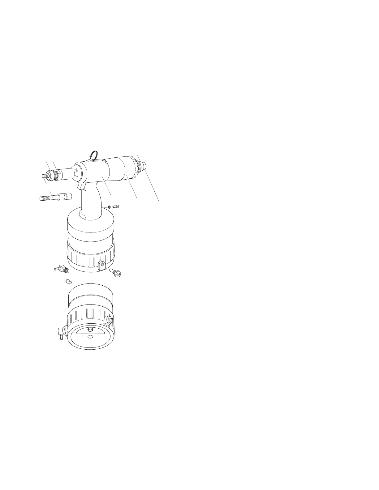
Description of the riveting tool
The riveting tool MS 100 is pneumatically - hydraulically actuated and has
an air motor.
It consists of the following operation-related components:
1Nose piece for threads M8, M10, M12 and M16
2Lock nut for fixing the nose pieces
3Mandrel for threads M8, M10, M12 and M16 of
blind rivet nuts
4Hang-up eyelet for hanging up on a hook whenever
stationary
5Hydraulic the pneumatic and the hydraulic
housing units are located in the hydraulic housing
6End cap is a complete unit enabling the switching of
the rotation of the air motor to left-handed
rotation
6.1 Adjustment screw is used for adjusting the end stop for the
automatic switching to the left-handed rotation
6.2 Button manually release the left-handed rotation
12
3
4
56
6.1
6.2
12
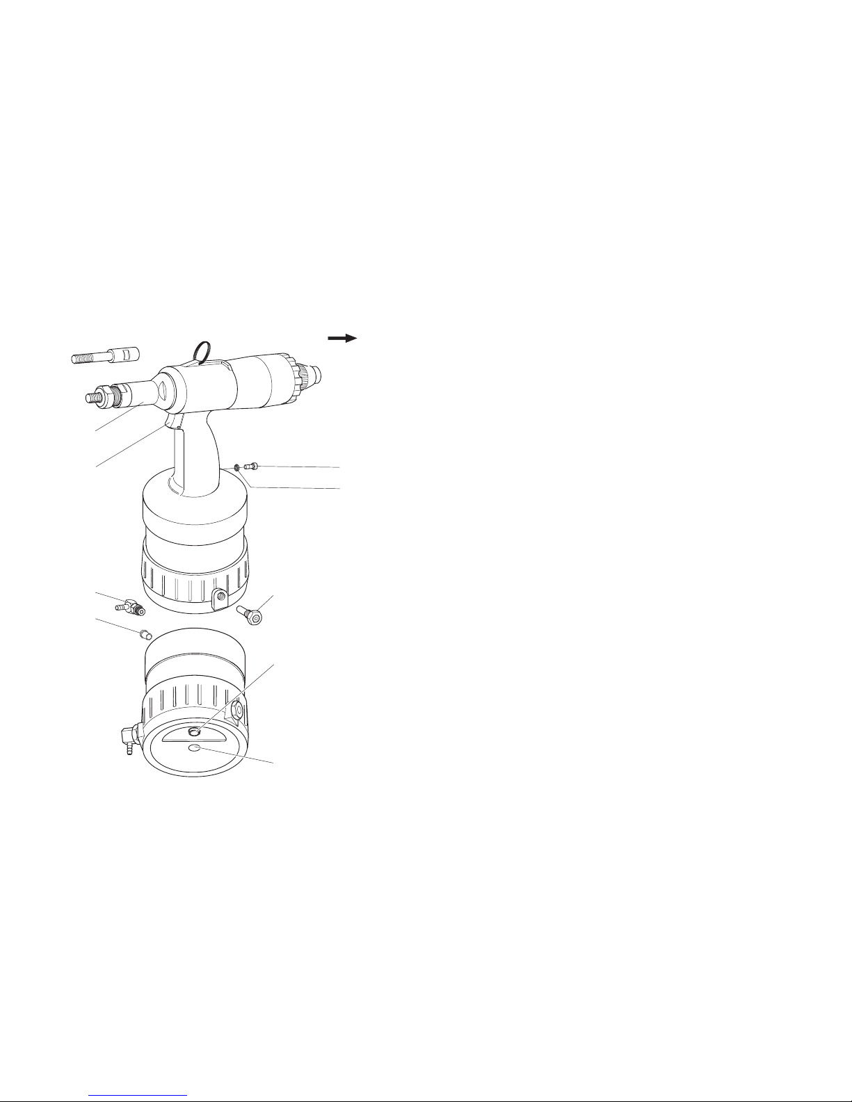
Description of the riveting tool
Note The socket head screw (7) and the O-ring (8) are screwed tightly
into the grip. The socket head screw (7) must not be loosened,
else the hydraulic oil will leak.
7Socket locking for the hydraulic oil system
head screw Opening serves as an oil inlet
8O-Ring Sealing of the hydraulic oil system
9Safety valve (Brass) In case of very high pressures
approx. 8 bar or more), it opens, and lets the
air out.
10 Plug serves the purpose of protection of the
thread and also against dirt
11 Swivel- serves as the connection for compressed air
joint hoses (operating pressure 6 bar)
12 Trigger — starts right-handed rotation
— triggers a riveting action
— stops left-handed rotation
13 Nose cap covered mandrel
15 Stroke is used to adjust the stroke
adjustment screw
7Socket head closes the opening to pull back the
screw in device pneumatic rod
floor
7
8
12
13
9
10
11
15
7

13
Required tools
You will require the following tools for all installation, servicing and mainte-
nance work.
Tools
— Crank (18)
— Wrench1SW13, SW17, SW27, SW30
— Internal hex key (19) SW4
1 No delivery possibility
SW13
SW17 SW30
19 SW27
18

14
Storing the riveting tool
Until first use
If you do not use the riveting tool immediately, store it inside the original
packing, dry and dust-free.
Long term storage after usage
Clean nose piece (1), lock nut (2), mandrel (3) and lubricate with acid-free
grease. Screw out the swivel joint (11) and close the opening with a
plug (10). If possible, store all pieces in the original packing.
After long-term storage
After long-term storage (about 3 years), change the hydraulic oil before
re-use.
Ahydraulic oil change may only be carried out by trained specialist with
the help of the service instructions. For further information regarding
service instructions and training, please see the address on page 42.
10
11
12
3
15
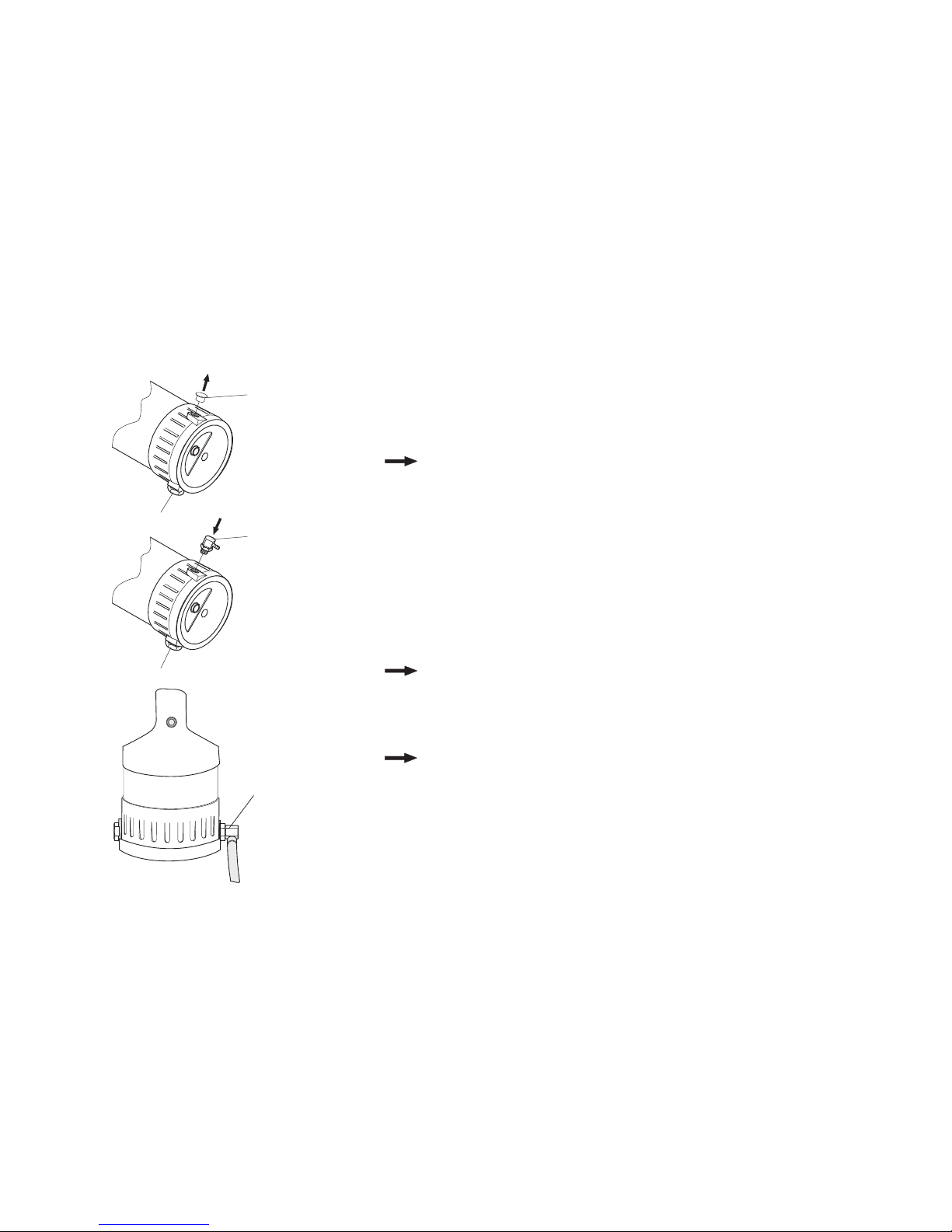
Preparing the riveting tool
The components ordered by you are marked as per the checklist found
inside the packing.
Note Please check the contents of the packing, for completeness of
the checklist
In every case, please carry out a visual check of the riveting tool before
starting any work:
— for external damages,
— for oil leakage from the riveting tool.
•Remove the plug (10) from the connection port and store in the original
packing.
Note The swivel joint (11) and the safety valve (9) can be alternative-
ly fitted on both the sides of the hydraulic housing. The diagram
below shows the arrangement for a right-hander.
Note In case of all screw-fittings, observe the table for torque values
in the chapter “Maintaining the riveting tool”
•Screw on the swivel joint (11) and tighten using the wrench SW17 (see
page 33 “Table for torque values”).
Package insert
11
10
9
9
1111
16
Preparing the riveting tool
H
E
E
Note Depending on the type of compressed air supply, it may be
necessary to connect a fitting different from the one provided,
to the riveting tool. For this, you need to have a fitting having a
1/4” Withworth-pipe-thread as per ISO 228.
Caution Danger of injury by running riveting tool. In this event, lightly
touch the trigger to stop the riveting tool.
Attention Material damage by compressed air!
As per norm ISO 8573-1, class 2, compressed air must be dry
and clean. We recommend that you fit a compressed air-main-
tenance unit to the riveting tool.
•Compressed air hose should be connected to the swivel joint (11), as
prescribed.
Attention Too narrow clearance can cause damage to material. If you
do not know the stroke setting, unscrew the adjustment
screw (6.1) for the automatic switching into the left-handed
rotation a few turns (ca. 5 mm). You thus make sure that
the rod does not strike the rear and the riveting tool is not
damaged.
Note The operating pressure must be between a minimum of 5 and a
maximum of 7 bar!
1111
6.1
17
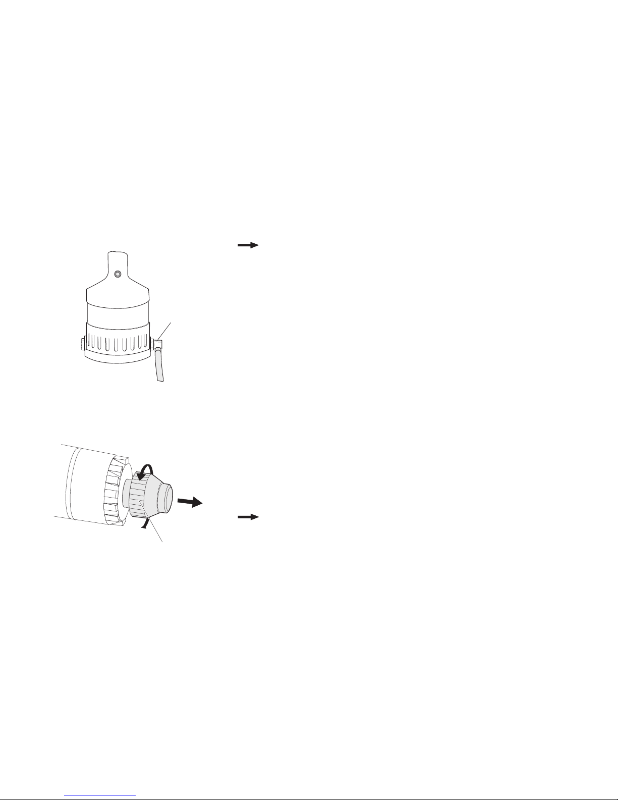
Adjusting the riveting tool
Note The standard fitting of the riveting tool is a mandrel M10. Align
the riveting tool to your conditions by replacing the mandrel
and/ or adjusting the stroke (H).
Changing the mandrel
Caution Risk of injury by crushing and shearing due to an accidental
working stroke! Always disconnect the compressed air supply
before unscrewing the nose cap (13).
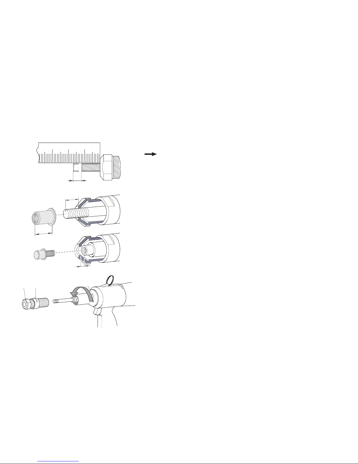
Attention Material damage! You have to readjust the length L (mandrel)
and the operating stroke (H) after every change. In addition to
this, the adjustment screw for the automatic switch over into
left-handed rotation (6.1) needs to be adjusted to the new
stroke.
•Select the corresponding mandrel and lubricate.
•Unscrew lock nut (2) with open wrench SW27.
•Unscrew nose piece (1).
•Loosen nose cap (13) with open wrench SW30 and screw off.
H
E
H
113
2
L
L
M

18
Adjusting the riveting tool
•Place open wrench SW13 on mandrel (3).
•Hold up locknut (14) to loosen mandrel and screw out.
Note Apply a little acid-free grease to the new mandrel.
Follow the table for tightening torques in the Chapter “Maintai-
ning the riveting tool”.
•Screw on new mandrel (3) (at least 6 turns) and tighten while holding up
the lock nut (14) (see page 33 “Table for torque values”).
•Screw on nose cap (13) and tighten with open wrench SW30
(see page 33 “Table for torque values”).
•Screw in appropriate nose piece (1).
Note Now first adjust the stroke. Then adjust the length L of the
mandrel (compare illustration on Page 17).
1
3
14
13
19
Adjusting the riveting tool
Adjusting stroke (H)
Note The correct stroke (H) depends on the type of blind rivet nut,
the thread size and material thickness (s). You will standard
values for the stroke in the table “Stroke adjustment dependent
on grip range” on page 23-24. The values given in the table
apply for blind rivet nuts that are sold by TITGEMEYER. If you
use blind rivet nuts of other manufacturers, get information from
the manufacturer if you do not have the applicable specifica-
tions.
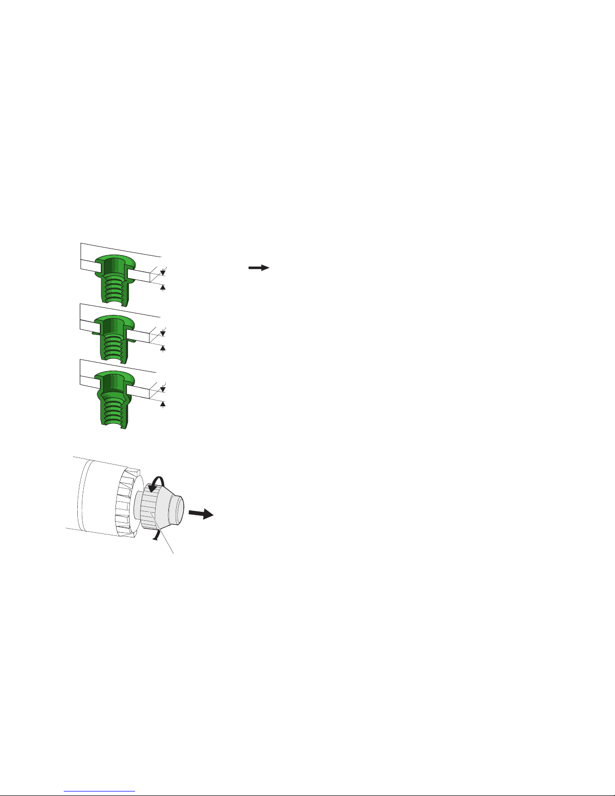
If the strength of the material deviates from the values, you must adjust
the stroke (H) accordingly:
— thinner material requires a larger stroke,
— thicker material requires a smaller stroke.
Attention Too narrow clearance can cause damage to material. If you
do not know the stroke setting, unscrew the adjustment
screw (6.1) for the automatic switching into the left-handed
rotation a few turns (ca. 5 mm). You thus make sure that
the rod does not strike the rear and the riveting tool is not
damaged.
Attention Material damage! Carry out test riveting after every adjustment
and check the deformation of the blind rivet nut. In the above
picture you can see the correct setting of a riveting, taking a
blind rivet nut as an example.
E
Stroke correct
Stroke too big
Stroke too small
s
s
s
6.1
20
Adjusting the riveting tool
19
15
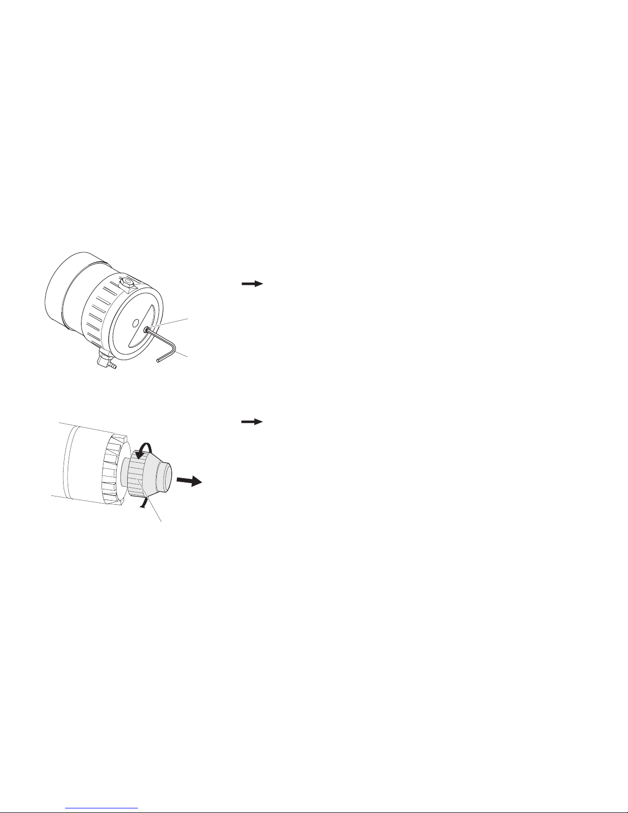
The adjustment to another working stroke follows on the underside of the
riveting tool. For this you need the spanner for internal hex key SW4 (19).
Note The stroke is approx. 9.0 mm when the stroke adjustment
screw (15) has been screwed out to the limit by left-handed
rotations
•Check if the compressed air hose is connected. If not, connect the
compressed air supply.
Using the spanner for hexagon nuts SW4 (19) turn the stroke adjustment
screw (15) in the relevant direction:
— right “-” reduce the stroke
— left “+” increase the stroke
Note Four turns of the stroke adjustment screw (15) correspond to a
stroke adjustment of 1 mm
Attention Material damage! If you do not know the stroke setting,
unscrew the adjustment screw (6.1) a few turns (ca. 5 mm) for
the automatic switch over to the left-handed rotation. This is to
ensure that the piston will not hit the back and the riveting tool
will not be damaged.
You must now measure the stroke (H) (see page 21).
E
6.1
Table of contents
Other Titgemeyer Power Tools manuals


Popular Power Tools manuals by other brands

Craftsman
Craftsman 572.610520 owner's manual

Festool
Festool Carvex PS 420 EBQ Original operating manual

Makita
Makita CG100D instruction manual

Nitto Kohki
Nitto Kohki delvo DLV45C Series instruction manual

Draper
Draper Storm Force SFASK1025 instructions

DeWalt
DeWalt XR LI-ION DCMAS5713 Original instructions


