TKR Group VAS 294 011A Instructions for use

VAS 294 011A
Granule jet blasting device
Translation of original instruction manual

2

3
www.tkr-support.com
1.
2.
3.
4.
5.
This instruction manual is protected by copyright. Any use outside of the boundaries of copyright law without
the consent of the manufacturer is not permitted and is punishable by law. This also applies to the extraction
of individual illustrations and the use of texts in excerpt form.
Chapter Page
1. Information regarding this manual 4
2. Permitted operators 4
3. Explanation of symbols 4
1. Intended use 5
2. Sources of danger 5
3. Safety devices 6
4. Safety measures at the setup location 7
1. Unpacking the device 8
2. Identification and description of the device components 8
3. Device components 9
4. Technical data 10
1. Operating the granule jet blasting device 10
2. Preparing and connecting the granule jet blasting device 11
3. Filling with blast medium 12
4. Connecting the suction hose to the suction unit 13
5. Attaching the blasting probe to the handle 14
6. Starting the cleaning process 15
7. Blasting 15
8. Cleaning the inlet valves and the inlet channel 16
9. Shutting down the device 17
1. Maintenance / cleaning 17
2. Replacement parts and accessories for the
granule jet blasting device 19
3. Warranty 20
4. EU Declaration of Conformity 21
1. Download current instruction manuals
2. Support

4
Note
State-of-the-art
Technical modifications
Reading the
instruction manual
Handling
Faults
Legislation stipulates that users must be trained in the use of manually operated blasting
equipment.
The granule jet blasting device is state of the art. To ensure that the equipment operates safely, it
must be operated in a proper and safe manner.
In the interests of quality assurance, we reserve the unrestricted right to apply technical
modifications arising out of further developments in technology and product improvements
without prior notification.
Read the instruction manual carefully before using the device.
All handling necessary to ensure correct operation is described in the instruction manual.
No working method which is not expressly approved by the manufacturer may be used. If the
device malfunctions during use, only trained technical personnel are permitted to repair it.
1.2 Permitted operators
1.3 Explanation of symbols
Follow the instruction
manual
Observe the general
instructions
Wear face mask
Wear hear protection
Wear gloves
Wear protective clothing
WARNING
Use of this machine with
nut granulates will produce
allergenic dust.
Persons allergic to nuts
should not use this machine
without adequate respiratory
safety equipment.
Several sections of these operating instructions are marked with internationally recognised warning signs, danger notes and general
prohibition signs. Please comply with all notes and safety rules! The individual symbols are explained in the following.
Follow all instructions and safety rules.
The owner/operator of the machine must make the operating instructions available to the operator and ensure
that they have been read and understood. Only then may the operator start up the device.
1.1 Information regarding this manual

5
The granule jet blasting device complies with the machinery directive 2006/42 EC and is used to treat the surface
of metal by means of a jet of granules blasted onto the metal surface. Compressed air is used to propel the blast
medium.
The granule jet blasting device is used to remove carbonized material from the inlet channel and valves of internal
combustion engines.
The jet blasting device may only be operated in combination with the vacuum adapters that are approved for the
particular engine type and a vacuum cleaner with sufficient suction power.
Unauthorised modifications or changes to the device are not permitted for safety reasons.
2.1 Intended use
2.2 Sources of danger
1.3 Explanation of symbols
Warning
General source of danger
Warning
System under pressure
Risk of hearing damage
Warning - noise with high
sound pressure level
Blow out with air
Clean with air/granule
mixture
Audibly engage
Please note the following!
Arrow to clarify
compression
Arrow indicating direction
For further information
see chapter...
The granule jet blasting device is safe if used for its correct purpose.
If it is used incorrectly and/or negligently by untrained personnel, serious injuries could be caused by the granules
emerging from the device.
The blasting probe must never be used without the suction adapter intended for it and a suction device of
sufficient power.
Never direct the blasting probe at persons or look into the opening of the blasting probe. Risk of injury!

6
2.3.1 2.3.2
2.2 Sources of danger
2.3 Safety devices
The device must only be operated using hoses which are approved for the purpose of use and the operating pressure of
the device.
The device may only be used by trained personnel.
• Never throw or drop the granule jet blasting device.
• The granule jet blasting device may only be used at ambient temperatures of between 5 °C and 45 °C.
• The granule jet blasting device must not be used in potentially explosive areas!
• The device must never be operated without suitable protective clothing, such as a safety mask and safety shoes. Risk
of injury!
The compressed air must be disconnected and the device depressurised before maintaining and cleaning or
filling the device with granules.
The granule jet blasting device may only be operated with compressed air.
The granule jet blasting device must always be set up on a level surface or the floor of the workshop. The device
must not be set up on tables, workbenches or other objects. (Tank is under pressure!)
Hoses and supply lines must be routed in such a way that they cannot be damaged or disconnected! The hoses must also
be routed in a way that prevents people from tripping over them.
chap. 5.1
chap. 2.4
Position B:
Operating
Position A:
Depressurise
Fig. 2.3.1
The compressed air must be disconnected
and the device depressurised.
Fig. 2.3.2
In the “Depressurise“ position, the tank and the
control system are switched to depressurise.

7
7
2.4.1
2.3.1
2.3 Safety devices
Fig. 2.4.1
The surface where the device is installed must be level and of
suitable load carrying capacity for the weight of the device and
must be stable.
The device may only be operated in association with the suction
adapters designed for the particular engine type and a vacuum
cleaner of sufficient size and power.
Hoses and feed pipes must be laid so that they cannot be dam-
aged or disconnected! The hoses must also be routed in a way
that prevents people from tripping over them.
2.4 Safety measures at the setup location
If a control function fails, the device must be taken out of service immediately and repaired by a trained technical
personnel!
There is a pressure gauge on the granules tank. The operating pressure of the device must never exceed 8 bar. A
safety valve is installed on the granules tank that controls the maximum operating pressure of the device. The
valve opens at pressure of approx. 8.5 bar.
If the safety setup location malfunction, the device must be taken out of service immediately! The device should
undergo preventive maintenance at least once per annum by a specialist company!
Fig. 2.3.3
There is a 2-way ball valve on the handle of the blasting probe. This can be operated in the event of failure of a control
function. When the ball valve is closed, no air or blasting medium can emerge from the probe.
8
3.1.1
3.2 Identification and description of the device components
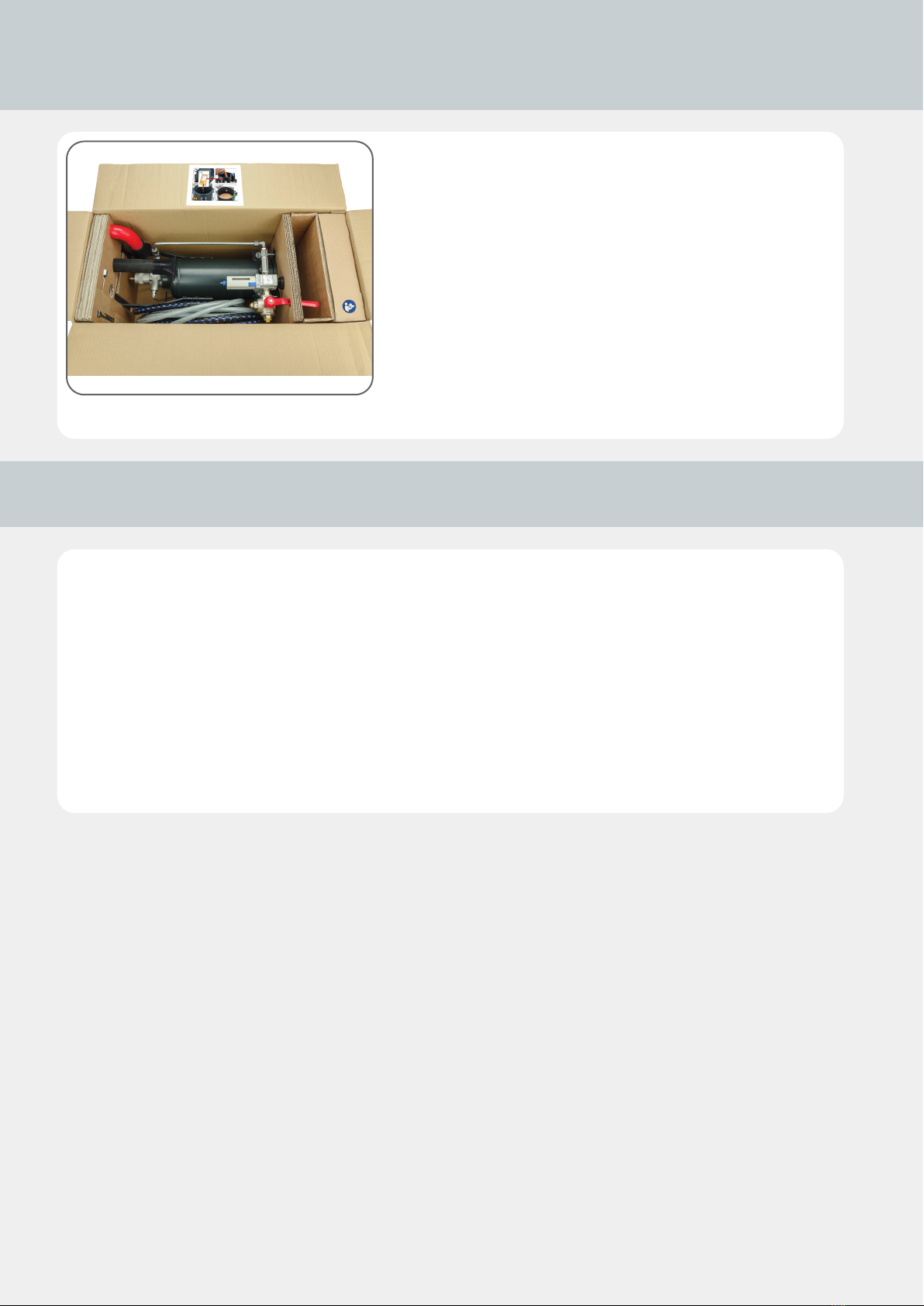
3.1 Unpacking the device
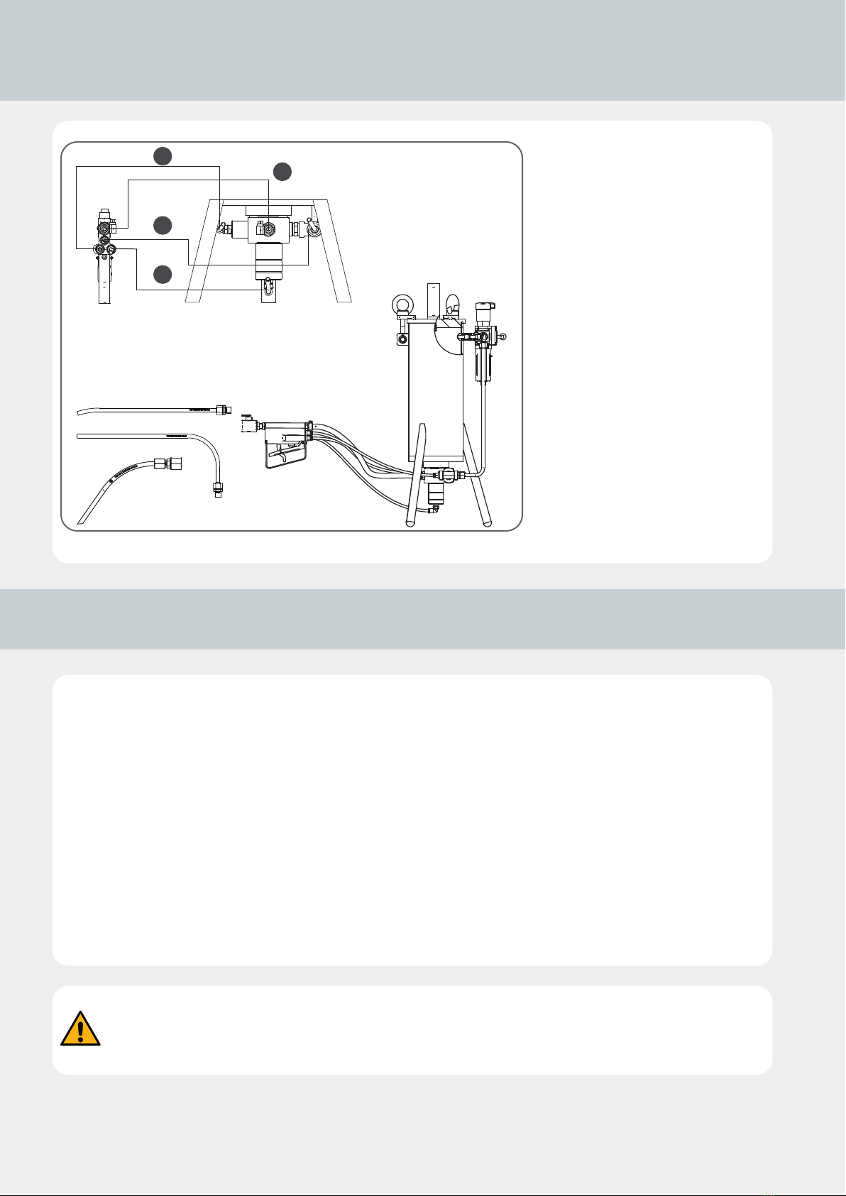
Main elements of the granule jet blasting device:
Granule blasting medium tank with 3-way ball valve, granules control valve, compressed air control valve and safety valve.
Hose assembly with granules delivery hose and three colour-coded control hoses.
Handle with 2-way ball valve and connection for the blasting probe. The control function in the handle is activated using two control
valves connected in series. The operating lever is fitted with a safety device to prevent the equipment restarting unintentionally.
• Place the box on a level surface.
• Open the box and carefully remove the device.
• Check the scope of supply:
- Operating instructions
- Granules tank with hose assembly
attached and handle
- Straight blasting probe
- Angled blasting probe
- 2x seals
- Suction hose 90°
- Suction hose 250 mm
- Container with nutshell granules

9
3.3.1
2
3
4
7
7
8
1
5
6
9
3.3 Device components
No. Title Quantity
1 Granule blasting device 1
2Straight blasting probe 1
3 Angled blasting probe 1
4Blasting probe 1
5 Suction hose 90° 1
6 Suction hose 250 mm 1
7Seal 2
8 Cleaning granulate –
9Instruction manual, complete 2
10
3.4.1
1
2
3
4
3.4 Technical Data
Length approx 290 mm
Width approx 280 mm
Height 610 mm
Max. operating pressure 8 bar
Container volume 5 l
Weight 16 kg
Hose package working length 4 m
Length and weight without hoses
4.1 Operation of the granule jet blasting device
• Fill with blasting granules.
• Connect the suction hose to the suction unit.
• Connect the seal and suction hose together.
• Attach the blasting probe to the handle.
• Attach the granule jet blasting device to the compressed air supply.
• Connect the suction hose to the opening on the engine and push the seal on the engine.
• Plug the blasting probe into the opening of the suction hose.
• Start the cleaning process.
• Clean the inlet valves and the inlet channel.
• Blow out: blast with air.
• Stop the compressed air supply.
• Shut down the device.
• Maintain the granule jet blasting device.
Always check the condition of the hoses before starting up the device!
Stop using defective hoses immediately. Risk of injury!
1 = Control air, black hose
2 = Main air, transparent hose
3 = Granules supply, blue hose
4 = Blasting medium hose, Ø14 mm
Straight blasting probe 3/3-way
control valve
Angled blasting probe
Blasting probe

11
4.2.14.2.1 4.2.2
4.2.4
4.2.3
4.2.5 4.2.6
4.2.84.2.7
G1/4G1/4“
R1/4“R1/4“
• Fill with blasting granules.
• Connect the suction hose to the suction unit.
• Connect the seal and suction hose together.
• Attach the blasting probe to the handle.
• Attach the granule jet blasting device to the compressed air supply.
• Connect the suction hose to the opening on the engine and push the seal on the engine.
• Plug the blasting probe into the opening of the suction hose.
• Start the cleaning process.
• Clean the inlet valves and the inlet channel.
• Blow out: blast with air.
• Stop the compressed air supply.
• Shut down the device.
• Maintain the granule jet blasting device.
4.2 Preparing and connecting the granule
jet blasting device
Fig. 4.2.1
The device is supplied from the factory
without a compressed air coupling. The
ball valve has a ¼ inch female threaded
connection. The thread is fitted with a
seal cap.
Fig. 4.2.2
Remove the sealing cap.
Fig. 4.2.3
Insert a suitable compressed air connec-
tor with seal into the thread.
Fig. 4.2.4
Tighten the compressed air connector
using a suitable tool.
The device must only be operated
using dry, oil-free compressed air!
Fig. 4.2.6
The granule jet blasting device has an in-
tegrated supply unit which enables you
to adjust the operating pressure.
Fig. 4.2.7 / 4.2.8
The operating pressure of the device
should be between 6 and 8 bar, and must
never exceed an operating pressure of
8 bar!
6 - 8 barmax. 8 bar
Ø 6 mm
≥ Ø 6 mm
12
4.3.24.3.1
4.3.3
4.3.64.3.6
4.3.4 4.3.5
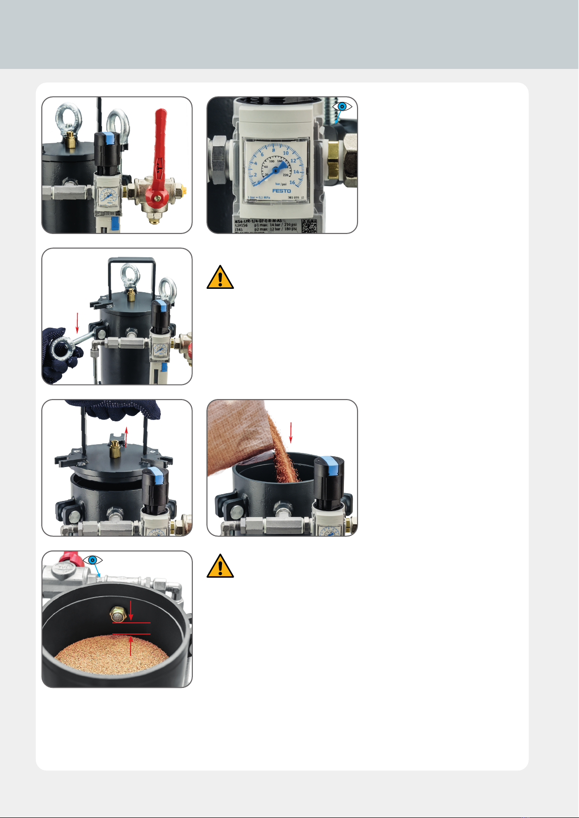
4.3 Filling with blasting medium
Warning! You must only fill the device when the tank is depressurised
anddisconnected from the supply line.
Only use a blasting medium which is approved by the manufacturer.
The blasting medium must be free of impurities.
Never re-use blasting medium.
Fig. 4.3.1
3-way ball valve in "Depressurise" posi-
tion (red lever).
Fig. 4.3.2
Pressure gauge must zero pressure.
Fig. 4.3.3
Undo eye bolts and swivel out swivelling
screw fitting.
Fig. 4.3.4
Remove the cover from the tank.
Fig. 4.3.5
Fill with granules.
Fig. 4.3.6
Max. filling level 20–30 mm below air inlet
connection.
20–30 mm
13
4.3.84.3.7
4.3.104.3.9
4.3.11
4.4.1
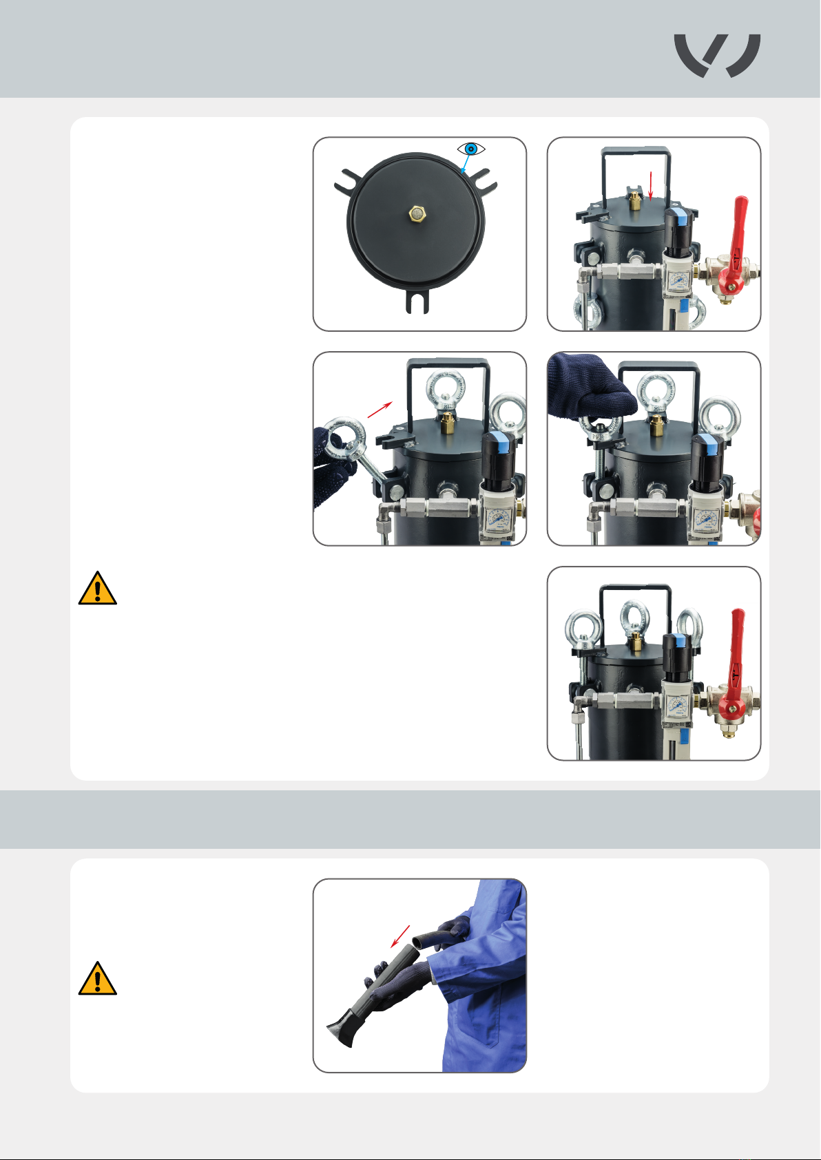
4.3 Filling with blasting medium
Fig. 4.3.7
Check sealing cap. The seal must be clean
and must not show any signs of damage.
Fig. 4.3.8
Place the cover on the tank.
Fig. 4.3.9
Engage the swivelling screw fitting.
Fig. 4.3.10
Tighten eye bolts by hand.
Fig. 4. 3.11
3-way ball valve in “Depressurise” position.
Fig. 4.4.1
Connect the suction hose to an industrial
vacuum cleaner.
Make sure that the suction hose is
firmly and securely connected to the
vacuum cleaner.
Check device for leaks!
If compressed air is leaking from the device, you must stop work and
eliminate the cause!
4.4 Connecting the suction hose to the suction unit

14
4.4.2
4.5.1 4.5.2
4.5.44.5.3
7
4.4 Connecting the suction hose to the suction unit
Fig. 4.4.2
Fix the suction hose in the inlet channel of the cylinder head.
Then, push the seal onto the engine block.
Fig. 4.5.1
Screw the correct blasting probe on to
the 2-way ball valve.
Fig. 4.5.2
Turn the 2-way ball valve to the open
position.
Fig. 4.5.3
Slowly turn 3-way ball valve to the oper-
ating position.
Fig. 4.5.4
No air must come out of the blasting
probe unless the hand lever is operated.
The device is now ready for operation!
Use the 90° suction hose (red) for transverse engines!
Use the 250 mm suction hose (black) for longitudinal engines!
Close or cover all openings except the one which is being worked on.
4.5 Attaching blasting probe to handle

15
4.6.24.6.1
4.7.1 4.7.2
2
1
2
1
4.6 Starting the cleaning process
4.7 Blasting
Before the cleaning process is started,
the operator must put on the prescribed
protective clothing!
Fig. 4.7.1
Blasting with air / blowing out
When the trigger is moved to position 1
(half-way position) only air comes out of
the blasting probe.
This operating position is used to blow
out the area to be cleaned.
Fig. 4.7.2
Blasting with air/granules mixture /
cleaning
When the trigger is moved to position 2
(pushed all the way) air and granules flow
out of the blasting probe with considera-
ble power.
This operating position is used to clean
the coked areas).
This device must only be used by trained and instructed technical
personnel!
Never pull the blasting probe out of the suction adapter during
the cleaning process!
Risk of injury!

16
4.8.1 4.8.2
4.8.3 4.8.4
4.8.5
4.8.6
7
3
4.8 Cleaning the inlet valves and the inlet channel
Fig. 4.8.1 – 4.8.4
The blasting probe must be positioned
close to the surfaces being cleaned. The
cleaning phases should last no more than
2-3 seconds. Then the area being cleaned
should be blown out again with air.
Alternate between cleaning and blowing
out several times. Each time the blast-
ing probe must be moved to a different
position so that the entire coked area is
cleaned.
Fig. 4.8.5
After all cleaning positions have been
blasted once, the cleaning result must
be visually inspected. If the result is un-
satisfactory, the process must be repeat-
ed and/or the operating pressure of the
device increased. Max. 8 bar!
Fig. 4.8.6
The inlet valves and the inlet channel
area should be bare and free of carbon-
isation.
When cleaning and blowing out, blast-
ing medium must not escape from the
suction adapter! If blasting medium is
escaping, the power of the suction unit
is not sufficient.

17
4.9.1
4.9.3
4.9.2
5.1.1 5.1.25.1.2
5.1.35.1.3
4.9 Shutting down the device
Fig. 4.9.1
After each operation the 3-way ball valve
must be moved to the "Depressurise"
position.
Fig. 4.9.2
The compressed air supply line can be dis-
connected when zero pressure is indicated
on the pressure control valve.
Fig. 4.9.3
Remove cover of blasting device and re-
move any remaining granules.
The granules must always be stored in
a dry place!
Never re-use granules!
Warning! The blasting medium hose is
also subject to wear during operation,
and must be checked for damage at
least every two months.
The blasting material hose should be
replaced once per annum if the device
is used regularly!
Fig. 5.1.1
Remove hose with protective braiding
from hose package.
Fig. 5.1.2, 5.1.3
Undo the hose clamps from the nozzle on
the control valve and on the handle.
5.1 Maintenance / cleaning

18
5.1.6
5.1.45.1.4 5.1.5
5.1.7
1 2 3
5.1.8
2
5.1.95.1.9
3
1
5.1.10
Fig. 5.1.4, 5.1.5
Removing and replacing the hose with a
new one.
Fig. 5.1.6
Use this occasion to examine all the hose
nozzles and connection nipples on the
control valve and on the handle.
If the size of the hole has been in-
creased significantly by the flow of
blasting material, it must be replaced!
Original diameter 6 mm
Wear limit diameter 7 mm
Fig. 5.1.7 – 5.1.9
Clean the filter inserts in the blasting
medium tank and the cover of the device
at regular intervals - after the tank has
been filled 10-15 times at most!
Fig. 5.1.10
Unscrew all filter inserts and blow them
out with a compressed air blow-out
gun from threaded side until all gran-
ule or dust residue has been removed.
After cleaning, the filter inserts must be
screwed back into the relevant positions.
Independently of the normal cleaning and maintenance work, the device must be checked and maintained at
least once per annum by a specialist company!
5.1 Maintenance / cleaning
6–7 mm

19
8
9
7
6
5
4
32
1
5.2.1
5.2 Spare parts and accessories for the
granule jet blasting device
Item No. Article Number Title
1 VAS 294 011/1A Granule blasting device
2 VAS 294 011/2 Straight blasting probe
3 VAS 294 011/3 Angled blasting probe
4 VAS 294 011/4 Suction hose 90°
5 VAS 294 011/5 Suction hose 250 mm
6 VAS 294 011/7 Seal
7 VAS 294 011/8 Cleaning granulate
8 VAS 294 011/9 O-ring
9 VAS 294 011/10 Blasting probe

20
5.3 Warranty conditions
Warranty restrictions
1. The warranty is invalidated if repairs are made to the device by anyone other than
a specialist company or the manufacturer.
2. The warranty is invalidated if the device is used for any other than its intended
purpose.
3. The warranty is invalidated if the operating instructions are not followed and the
maintenance work has not be carried out as stipulated.
4. The warranty is invalidated if the device is used incorrectly and/or the permitted
operating parameters are exceeded.
5. The warranty is invalidated in the event of external effects such as transport damage
and damage caused by impacts or collisions.
6. Repairs which have been carried out by unauthorised third parties.
7. Normal wear to the blasting probes, blasting hoses including handle and the granule
control valve is not covered by the warranty.
Service address
TKR Spezialwerkzeuge GmbH
Am Waldesrand 9–11
D-58285 Gevelsberg (Germany)
Phone +49 2332 66607-0
Fax +49 2332 66607-941
E-mail info@tkrgroup.com
Internet www.tkrgroup.com
This device complies with the current safety regulations and was tested before leaving the factory. We provide
a 24 month warranty and are obliged to carry out all repairs caused by material and/or manufacturing faults
that become necessary during this time.
Table of contents
Other TKR Group Industrial Equipment manuals


