2
Instruction Manual
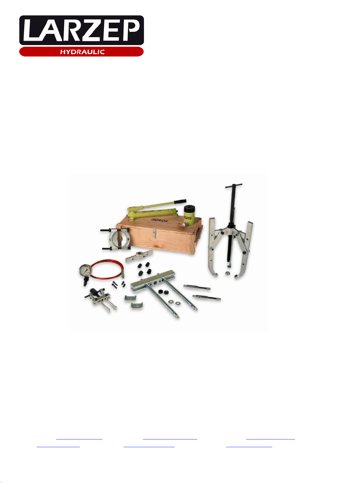
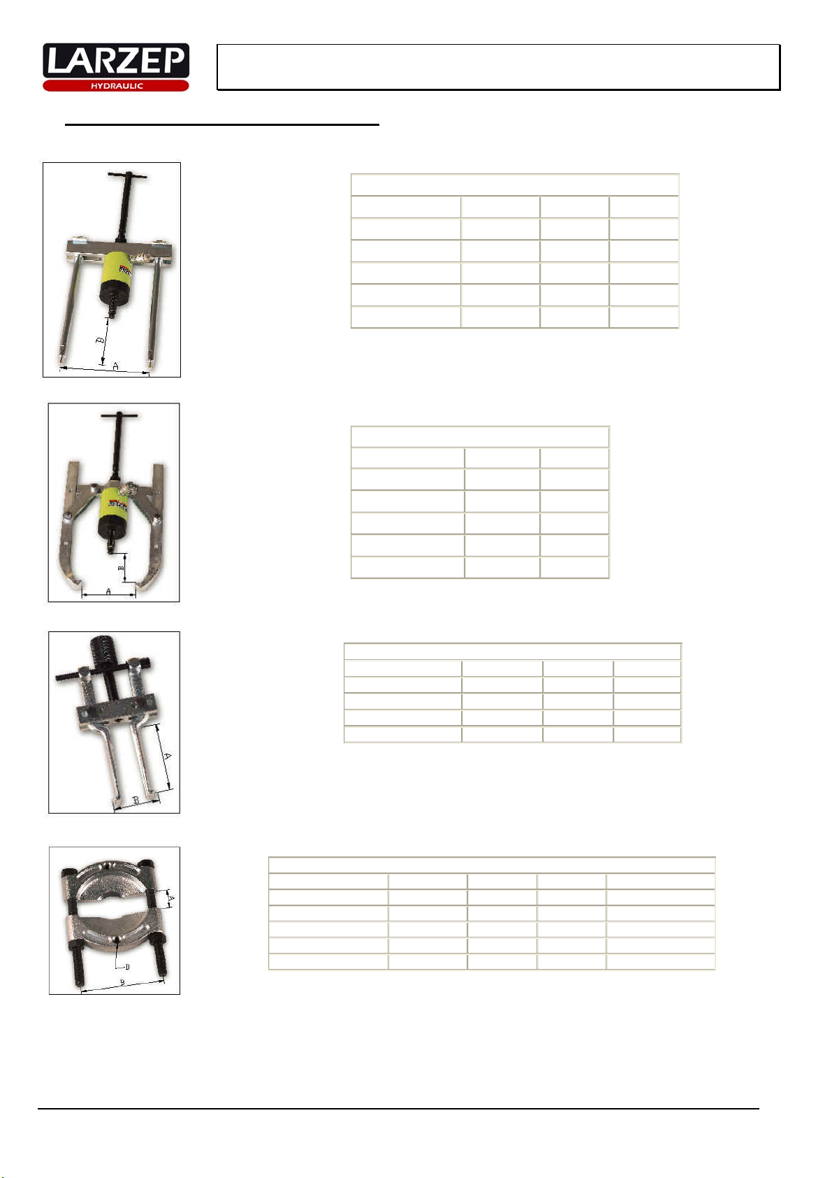
Hydraulic Pullers
INDEX
1. ESSENTIAL SAFETY REQUIREMENTS .................................................2
2. WARRANTY ..................................................................................................3
3. TECHNICAL FEATURES............................................................................3
4. START UP...................................................................................................4-5
5. MAINTENANCE............................................................................................5
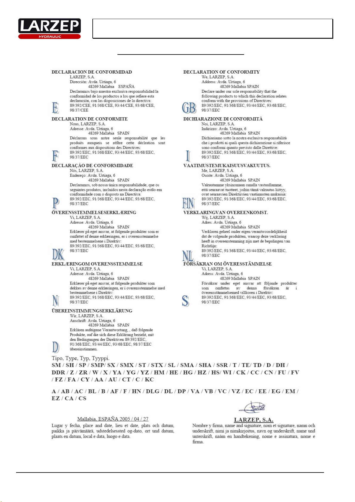
6. DECLARATION OF CONFORMITY.........................................................6
ANNEX
GENERAL DRAWING, PARTS AND DIMENSIONS
1. ESSENTIAL SAFETY REQUIREMENTS.
The LARZEP hydraulic pullers has been designed and manufactured in compliance to our quality standards and under the supervision and control that the ISO 9001
rules forces.
An inadequate use of the equipment could cause hard physical damages to the operator, as well as the machine or the treated material.
The use of the machine must be done in perfect technical conditions and in accordance to the considerations described in the present manual. The operator must know
the inherent risk to the use of high pressure hydraulic elements and must be perfectly trained in the machine working.
This equipment has been designed only for the applications described in this manual, other kind of uses are not foreseen and so, LARZEP, S.A. will not be
responsible in any case of the damages caused by an inadequate use.
The instructions must be always available for the operator. In addition to the instruction manual, the operator must be trained in the use of the machine, the rules and
standards corresponding to this kind of applications; such as: Accident prevention, environmental protection, etc.
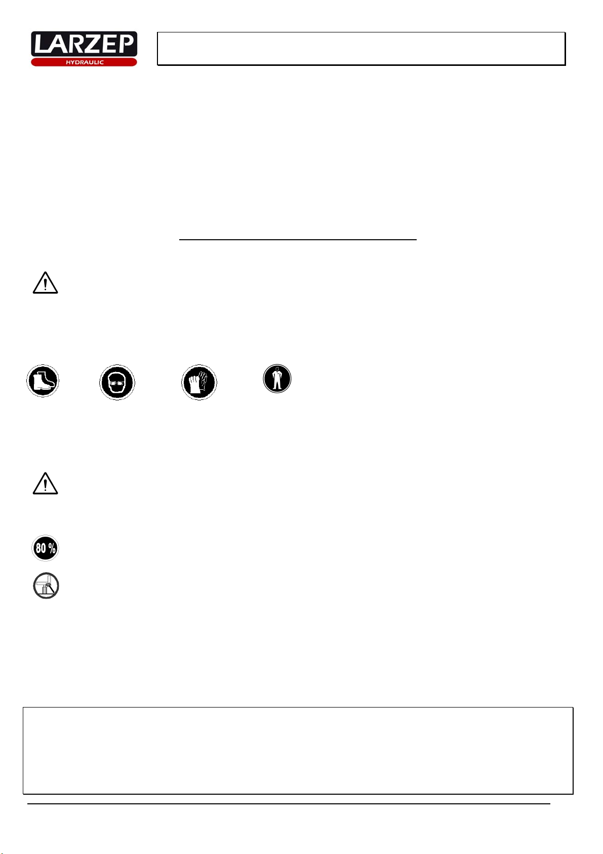
The exposed personnel must use protective devices such as: Boots, Goggles, Gloves, Clothes, etc. depending on the application.
Boots Goggles Gloves Clothes
In every new use of the equipment, follow the START UP chapter of the present manual.
Never modify the equipment or add elements that could affect to the security without the manufacturer authorization.
The repairs, maintenance operations, etc. only will be done by specialist personnel and with original LARZEP spare parts.
Replace periodically the hydraulic hoses if they are part of the installation although they do not seem damaged.
Make the maintenance operations regularly as we explain in the manual, all this operation must be done with depressurized and disconnected equipments.
Once the operation is done, disconnect the equipment, clean and store it in a clean and safety place.
In case of see a bad function of the machine or any of the components of the installation, stop the application immediately, block the system and
if it is possible, solve the problem.
Before start the operation assure that there is not anybody exposed in the dangerous zone. Check that the machine and the accessories has not suffered damages
during the transport or installation. Always use the equipment in well-lit areas.
All the material of the installation must be in stable zone and the operator must foresee the movements of the application.
Choose the most suitable model for the application from the wide range available, and make sure that it will not exceed 80% of its nominal
capacity during normal operation.
Do not exposure the equipment to intense heat sources (welding).
Include control elements (pressure gauges) in the installation in order to enable the operator to monitor the pressure in the system and ensure that the equipment’s
nominal capacity is never exceeded. Be prepared to use safety valves and accessories if the safety criteria so demand.
The pump controls should be activated manually, as should the connections between elements equipped with quick plugs.
Clean the quick plugs before connecting and make sure the connections are perfect (first insert as far as the plug will go and then screw in by hand). A bad
connection may result in improper functioning and may even generate a safety hazard.
Install the device in such a way as to ensure that the hoses are not subjected to sharp or forced bends or thrust actions that may cause them to break.
Do not modify the device (welded parts, lengthening drive levers, etc.) without consulting the manufacturer.
Do not use the hoses for transporting the device. Use the handles on the cylinders (when appropriate) and set the pump lever to the transportation position.
When filling the pump with oil, always use LARZEP hydraulic oil or another oil of similar characteristics. Fill only to the indicated level and remember that the
cylinder piston should be retracted.
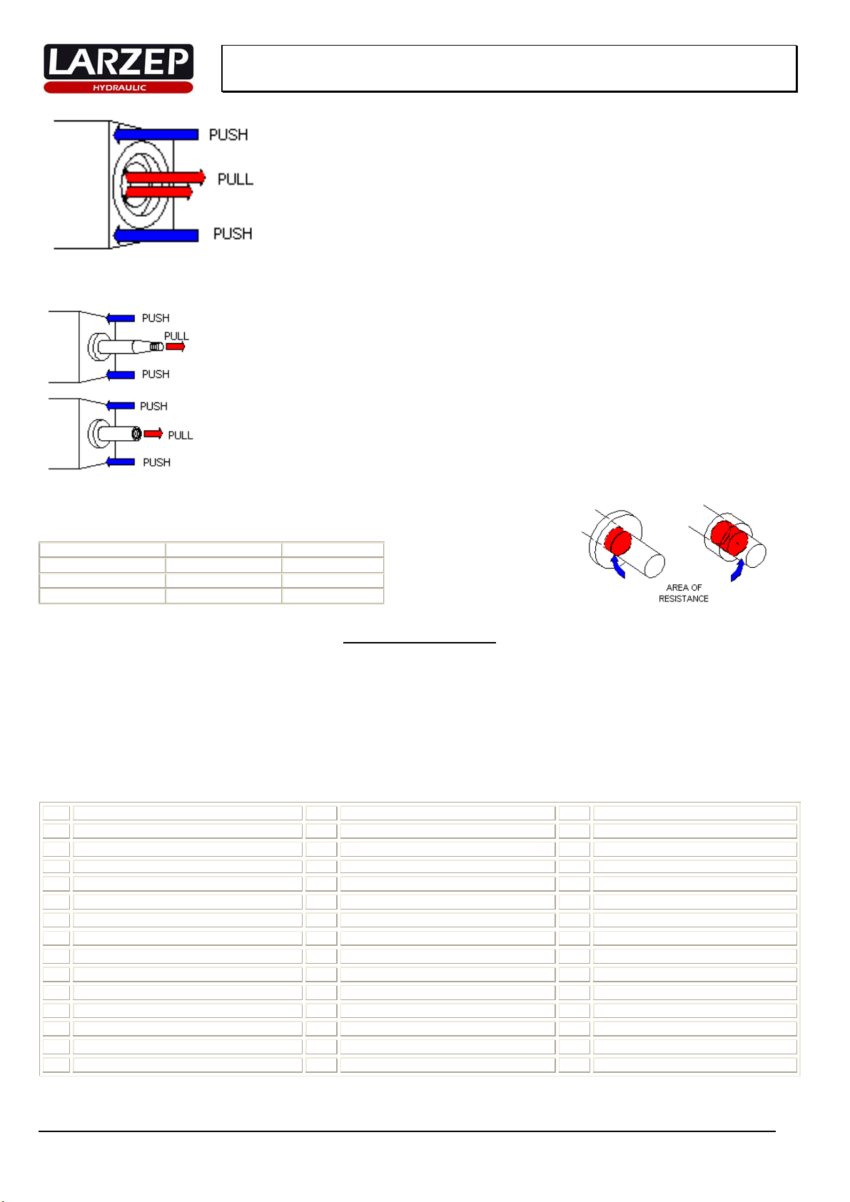
BREAK PREVENTION:
Check for perfectly tightened extenders, nuts and guillotine. Keep spindle greased and extenders centred.
When the pieces to be pulled are forced to work in bad conditions, we must reduce the maximum load applied to the puller. As standard, we’ll
reduce to half of the load.
The break will never be dangerous because there’s no risk of element projection. (Puller’s parts). This danger is fictitious; it always seems to be
dangerous due to the noise and the commotion that a big puller provokes when broken.
The unique risk when broken; and this case is improbably, is the falling down of the puller due to the lost of the supporting point. (It doesn’t
happen because generally an extender and the spindle are enough to support it.)