TKS FeedBelt - Lite User manual

1
TKS Operator's manual
988831FeedBelt LITE EN, issue 1, 2014-04
Operator’s manual
FeedBelt - Lite

2
TKS Operator's manual
Content
1 GENERAL INFORMATION AND SAFETY . . . . . . . . . . . . . . . . . . . . . . . . . . . . . . . . . . . 6
2 OPERATOR'S MANUAL . . . . . . . . . . . . . . . . . . . . . . . . . . . . . . . . . . . . . . . . . . . . . . . . 18
3 MANUAL FEEDING. . . . . . . . . . . . . . . . . . . . . . . . . . . . . . . . . . . . . . . . . . . . . . . . . . . . 30
4 AUTOMATIC FEEDING . . . . . . . . . . . . . . . . . . . . . . . . . . . . . . . . . . . . . . . . . . . . . . . . . 31
5 EXAMPLE OF GROUP ADJUSTMENT . . . . . . . . . . . . . . . . . . . . . . . . . . . . . . . . . .32
6 SMS MESSAGES . . . . . . . . . . . . . . . . . . . . . . . . . . . . . . . . . . . . . . . . . . . . . . . . . . . .33
7 MAINTENANCE AND CARE . . . . . . . . . . . . . . . . . . . . . . . . . . . . . . . . . . . . . . . . . . .35
8 ALARMS AND TROUBLESHOOTING. . . . . . . . . . . . . . . . . . . . . . . . . . . . . . . . . . . 42
9 CIRCUIT DIAGRAM - MASTER CABINET LITE. . . . . . . . . . . . . . . . . . . . . . . . . . . . . .44
10 CIRCUIT DIAGRAM - SLAVE CABINET LITE . . . . . . . . . . . . . . . . . . . . . . . . . . . . . .49
2 General information and safety . . . . . . . . . . . . . . . . . . . . . . . . . . . . . . . . . . . . . 6
1.1 CE - Declaration of conformity . . . . . . . . . . . . . . . . . . . . . . . . . . . . . . . . . . . . . . . . . . 6
1.2 Guarantee . . . . . . . . . . . . . . . . . . . . . . . . . . . . . . . . . . . . . . . . . . . . . . . . . . . . . . . . . . 7
1.3 Introduction . . . . . . . . . . . . . . . . . . . . . . . . . . . . . . . . . . . . . . . . . . . . . . . . . . . . . . . . . 8
1.4 Technical data - FeedBelt . . . . . . . . . . . . . . . . . . . . . . . . . . . . . . . . . . . . . . . . . . . . . . 9
1.4.1 Model description and area of use . . . . . . . . . . . . . . . . . . . . . . . . . . . . . . . . . . . 9
1.4.2 Machine identifi cation. . . . . . . . . . . . . . . . . . . . . . . . . . . . . . . . . . . . . . . . . . . . 10
1.4.3 Main dimensions - FeedBelt with 1 center-section. . . . . . . . . . . . . . . . . . . . . . 11
1.5 Safety . . . . . . . . . . . . . . . . . . . . . . . . . . . . . . . . . . . . . . . . . . . . . . . . . . . . . . . . . . . . 12
1.5.1 General safety instructions. . . . . . . . . . . . . . . . . . . . . . . . . . . . . . . . . . . . . . . . 12
1.5.2 Additional safety instructions . . . . . . . . . . . . . . . . . . . . . . . . . . . . . . . . . . . . . .14
1.5.3 Overview of safety risks . . . . . . . . . . . . . . . . . . . . . . . . . . . . . . . . . . . . . . . . . . 15
1.5.4 Lifting the FeedBelt by assembling . . . . . . . . . . . . . . . . . . . . . . . . . . . . . . . . . . 16
1.5.5 New machine - be careful. . . . . . . . . . . . . . . . . . . . . . . . . . . . . . . . . . . . . . . . . 16
1.5.6 Installation and commissioning. . . . . . . . . . . . . . . . . . . . . . . . . . . . . . . . . . . . . 16

3
TKS Operator's manual
1.6 Recycling - waste to resource - . . . . . . . . . . . . . . . . . . . . . . . . . . . . . . . . . . . . . . . . 17
2 Operator's manual. . . . . . . . . . . . . . . . . . . . . . . . . . . . . . . . . . . . . . . . . . . . . . . 18
2.1 Use of the PLC - LITE . . . . . . . . . . . . . . . . . . . . . . . . . . . . . . . . . . . . . . . . . . . . . . . . 19
2.2 Menu-tree - LITE . . . . . . . . . . . . . . . . . . . . . . . . . . . . . . . . . . . . . . . . . . . . . . . . . . . . 20
2.3 PLC menu - screens . . . . . . . . . . . . . . . . . . . . . . . . . . . . . . . . . . . . . . . . . . . . . . . . . 21
2.4 Other screen . . . . . . . . . . . . . . . . . . . . . . . . . . . . . . . . . . . . . . . . . . . . . . . . . . . . . . . 29
3 Manual feeding . . . . . . . . . . . . . . . . . . . . . . . . . . . . . . . . . . . . . . . . . . . . . . . . . 30
4 Automatic feeding . . . . . . . . . . . . . . . . . . . . . . . . . . . . . . . . . . . . . . . . . . . . . . . 31
5 Example of group adjustment . . . . . . . . . . . . . . . . . . . . . . . . . . . . . . . . . . . . . 32
6 SMS messages . . . . . . . . . . . . . . . . . . . . . . . . . . . . . . . . . . . . . . . . . . . . . . . . . 33
6.1 Received messages. . . . . . . . . . . . . . . . . . . . . . . . . . . . . . . . . . . . . . . . . . . . . . . . . . . 33
6.2 Sent messages . . . . . . . . . . . . . . . . . . . . . . . . . . . . . . . . . . . . . . . . . . . . . . . . . . . . . 34
7 Maintenance and care. . . . . . . . . . . . . . . . . . . . . . . . . . . . . . . . . . . . . . . . . . . . 35
7.1 Screw and bolt torque:. . . . . . . . . . . . . . . . . . . . . . . . . . . . . . . . . . . . . . . . . . . . . . . .35
7.2 Storing the FeedBelt . . . . . . . . . . . . . . . . . . . . . . . . . . . . . . . . . . . . . . . . . . . . . . . . . 35
7.3 Weekly inspections . . . . . . . . . . . . . . . . . . . . . . . . . . . . . . . . . . . . . . . . . . . . . . . . . . 36
7.4 Lubrication . . . . . . . . . . . . . . . . . . . . . . . . . . . . . . . . . . . . . . . . . . . . . . . . . . . . . . . .37
7.5 Oil change . . . . . . . . . . . . . . . . . . . . . . . . . . . . . . . . . . . . . . . . . . . . . . . . . . . . . . . . 37
7.6 Tightening the belt . . . . . . . . . . . . . . . . . . . . . . . . . . . . . . . . . . . . . . . . . . . . . . . . . . .38
7.7 Tensioning the wire . . . . . . . . . . . . . . . . . . . . . . . . . . . . . . . . . . . . . . . . . . . . . . . . . . 39
7.8 Shifting device adjustment. . . . . . . . . . . . . . . . . . . . . . . . . . . . . . . . . . . . . . . . . . . . . 39
7.9 Tighening torque for screws and bolts . . . . . . . . . . . . . . . . . . . . . . . . . . . . . . . . . . . 40
7.10 Cleaning the FeedBelt. . . . . . . . . . . . . . . . . . . . . . . . . . . . . . . . . . . . . . . . . . . . . . .40

4
TKS Operator's manual
8 Alarms and troubleshooting. . . . . . . . . . . . . . . . . . . . . . . . . . . . . . . . . . . . . . 42
9 Circuit diagram - Master cabinet LITE. . . . . . . . . . . . . . . . . . . . . . . . . . . . . . . 44
9.1 Circuit diagram - Power supply . . . . . . . . . . . . . . . . . . . . . . . . . . . . . . . . . . . . . . . . . 44
9.2 Circuit diagram - Inputs . . . . . . . . . . . . . . . . . . . . . . . . . . . . . . . . . . . . . . . . . . . . . . . 45
9.3 Circuit diagram - Outputs. . . . . . . . . . . . . . . . . . . . . . . . . . . . . . . . . . . . . . . . . . . . . . 46
9.4Circuit diagram - Connections . . . . . . . . . . . . . . . . . . . . . . . . . . . . . . . . . . . . . . . . . .47
9.5 Circuit diagram - Panel . . . . . . . . . . . . . . . . . . . . . . . . . . . . . . . . . . . . . . . . . . . . . . .48
10 Circuit diagram - Slave cabinet LITE . . . . . . . . . . . . . . . . . . . . . . . . . . . . . . . 49
10.1 Circuit diagram . . . . . . . . . . . . . . . . . . . . . . . . . . . . . . . . . . . . . . . . . . . . . . . . . . . 49
10.2 Circuit diagram - Panel . . . . . . . . . . . . . . . . . . . . . . . . . . . . . . . . . . . . . . . . . . . . .50
FeedBelt - LITE Menu-tree. . . . . . . . . . . . . . . . . . . . . . . . . . . . . . . . . . . . . . . . . . . . . . . . . 51
Notes . . . . . . . . . . . . . . . . . . . . . . . . . . . . . . . . . . . . . . . . . . . . . . . . . . . . . . . . . . . . . . . . . 52

5
TKS Operator's manual

6
TKS Operator's manual
1 General information and safety
1.1 CE - Declaration of conformity
We,
TKS Agri AS,
Kvernelandsvegen 100
N-4355 Kverneland
Norge
declare that the product:
TKS - FeedBelt LITE
has been built in conformity with the Machine Directive and meets the relevant
fundamental health and safety requirements.
Kverneland, 03 Mai 2013
Atle Sjølyst - Kverneland
General Manager
Enter the serial number
of the machine here:
TKS Agri AS, manufacturer of agricultural products, reserves the right
to change the design and/ or specifi cations of its products without prior warning.
This does not imply any obligation to modify previously supplied machines.

7
TKS Operator's manual
1.2 Guarantee
This TKS product is guaranteed against manufacturing and material defects for one year.
If the owner wishes a defect to be covered by the product guarantee, he or his representative must
inform the dealer of this when ordering parts and/or repairs. Claims must be reported within the
guarantee period.
The dealer must complete a claims form for each case covered by a guarantee and send it to TKS
or TKS’s distributor/importer within the 10th of the month following the one in which the defect was
reported.
The defective parts shall be marked with the claim number and be kept for up to 6 months so that
TKS or TKS’s distributor/importer can inspect them.
Since TKS products are used outside the manufacturer’s control, we can only guarantee the
product quality, and not that it will perform its function, nor are we liable for any resulting damage.
Warranty does not apply if:
a) third-party spare parts are used, or the product is repaired or altered without the
approval of TKS
b) the operating and servicing instructions have not been followed
c) the machine has been used for other purposes than those for which it is designed
The guarantee does not cover damage due to normal wear and tear.
Offi cial safety regulations specify requirements that apply to the manufacturers of this machine
relating to the careful review of safety hazards that may arise when this type of machine is used
correctly. Therefore, TKS and our importer/distributor are not responsible for the functioning of
components that are not shown in the spare-parts catalogue for this product.
TKS reserves the right to change the design of the product without this implying any obligations in
relation to previously supplied machines.
NB!
It must be possible to identify all enquiries relating to this product by the product’s serial number;
see page 8 on Machine identifi cation.

8
TKS Operator's manual
1.3 Introduction
Congratulations on buying your new TKS product. You have chosen a functional, high quality
product. A network of helpful dealers will be able to advise you on its use, as well as provide
servicing and spare parts.
All TKS products are designed, tested and built in close cooperation with farmers and machine
workshops to ensure optimal effi ciency and reliability.
Please read this instruction manual carefully and familiarise yourself with the machine’s manner of
operation before starting to use it.
Many diff erent factors and variables may impact on the machine’s function and operation.
It is therefore very important to consider all known factors and adapt the way in which the machine
is used accordingly.
A good understanding of the machine’s method of operation and performance, together with a
sound knowledge of the feeding process and feed types/consistency, will ensure the best results.
The machine is highly advanced, operates unsupervised and must be used in accordance with the
manufacturer’s instructions and other applicable regulations.
By being thorough and making the necessary adaptations to local conditions, you will ensure the
best possible results.
Yours faithfully
TKS Agri AS
TKS Agri AS,
Kvernelandsvegen 100
N-4355 Kverneland
Norway
www.tks-as.no
e-post : post@tks-as.no
Phone : + 47 51 77 05 00
Fax : + 47 51 48 72 28

9
TKS Operator's manual
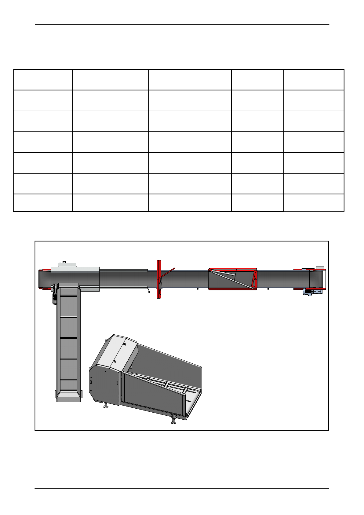
1.4 Technical data - FeedBelt
1.4.1 Model description and area of use
The TKS FeedBelt is designed to transport diff erent types of forage, concentrates and shavings to
milk cows via the feeding passage. The forage is released down over the milk cows into the feed-
ing passage using a scrape carriage.
The scrape carriage is controlled via a wire which can be moved to the right or left so that the
forage is distributed to both sides of the feeding passage using the belt and a stop system. The
reversing bow is used to adjust the scrape from right to left.
It is supplied with a main cabinet, which is located at the end where the forage is added.
Control cabinet for drive unit – belt. Three switches which receive signals.
• The belt is powered by a gear motor in the drive roller
• The scraper is powered by a gear motor via the wire and is positioned with the aid of a sensor.
• The belt is fed forwards on top of a channel and returns on rollers placed inside the channel.
• The drive roller has a friction coating to improve the reliability of the belt operation.
• The counter-roller ensures a better connection with the drive roller.
• The belt and wire have sensors that indicate their movement.
• A brush is positioned against the belt next to the drive roller.
The brush ensures that the belt is kept clean.
• The machine is installed at various heights above the feed trough.
• The channel is installed on portals or brackets with a maximum length of 6 m between them.
• The feed is conveyed onto the belt at the opposite end of the drive roller.
• Suitable side panels position the feed in the centre of the belt.
• Forage can be added to the belt from various fi lling sources.
• Feed must be fed onto the belt at an even pace, preferably from a conveyor.
• FeedBelt can operate multiple fi lling sources and conveyors, depending on the control cabinet.
• Forage can be dispensed on a time or weight basis.
• Minimum operating temperature -20°C.
NB! The instructions given in this operator’s manual apply to standard operating conditions.
Individual circumstances may arise at the premises of the user that deviate from the instructions
provided here. Changes to the machines and equipment as a result of such circumstances shall
not constitute grounds for making a claim against the manufacturer or supplier.
NB!
Think safety when using the FeedBelt.
Individual users must observe the provisions, rules and standards that apply in the country
concerned.
FeedBelt
Belt width in mm 500mm
Motor output - belt 2,2kW 230V - 14,1A
Scrape motor eff ekt 1,1kW 230V - 8,6A

IFB_02
10
TKS Operator's manual
1.4.2 Machine identifi cation
The machine’s serial number and the manufacturer’s address are written on a plate on the
machine. See the illustration on this page.
Vennligst bruk opplysningene på skiltplaten ved alle reservedels- og servicehenvendelser.
Please use this information when making any enquiries about spare parts or servicing.
This product is CE marked. This mark, along with the associated written EU confi rmation, means
that the product fulfi ls current health and safety requirements, and complies with the following
directive: Machine Directive.
MFB_01
IFB_02
11
TKS Operator's manual
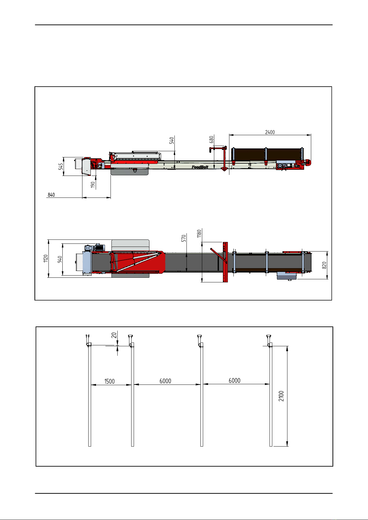
1.4.3 Main dimensions - FeedBelt with
1 center-section
All dimensions are in mm
Last feeding
Min. scrape height
Min. schifting device height
First feeding
12
TKS Operator's manual
1.5
Safety
Please pay particular attention to this symbol.
It designates a safety risk, and describes
precautions that must be taken to avoid
accidents
Before operating, adjusting or repairing the
machine, the user, technician or owner should
familiarise himself with the safety instructions
contained in this installation manual.
Pay attention and be careful when handling
agricultural machinery. Read and take note of
the safety instructions in this manual
Safety at work is your responsibility!
1.5.1
General safety
instructions
Please read and understand these general
safety instructions.
Use of the machine
The machine must only be used for the purpose
for which it is designed.
How the machine works
The operator must familiarise himself with how
the machine works and functions, so that it can
be used safely and properly.
Keep a safe distance
Keep away from operating, rotating and
moving parts.
Think safety at work
Never climb on the machine’s belt while it is
operating. The power supply must be
disconnected
before any maintenance is carried out.
Protective screens
Check that all screens are in place and installed
correctly. Do not start the machine until this has
been done.
Damaged screens must be repaired or replaced
immediately.
Spare parts
For safety reasons we recommend that you
only use original spare parts. The use of
third-party spares invalidates the product
guarantee.

13
TKS Operator's manual
Maintenance
Make sure that the machine is well-maintained
and kept in good condition.
Never make alterations to the machine’s
structures.
Control panel
The power supply must be isolated before the
panel is opened.

14
TKS Operator's manual
Fig. 3
1.5.2
Additional safety
instructions The machine is marked with a warning
signs. If these signs are damaged, they must
be replaced. The order number is shown on the
illustrations in this section.
See picture on page 8 for their location on the
machine.
Warning sign UH220532 (Fig. 1)
Be careful! Ensure that you read and under-
stand the instruction manual before using the
machine, and before making any adjustments
or performing any maintenance.
Warning sign UH220539 (Fig. 2)
Finger fracture warning sign. Risk of fi nger
fracture if fi ngers are trapped between the
carrier and lower frame.
Warning sign 988010 (Fig. 3)
The belt must be kept tight, it is
therefore important and necessary to retighten
the screws regularly.
Fig. 1
Fig. 2

UH220532
UH220539
988010
IFB_05
15
TKS Operator's manual
1.5.3 Overview of safety risks
Fig. 4
MASTER CABINET SLAVE CABINET
IFB_36
16
TKS Operator's manual
1.5.4
Lifting the FeedBelt -
by assembling
Vær forsiktig!
Use approved lifting equipment only.
Ensure that no one is underneath or near the
FeedBelt when the various sections are fi tted
into place.
1.5.5
New machine -
be careful
Read the operator’s manual
Take special care when starting a new machine
for the fi rst time. Incorrect installation,
operation etc. may lead to costly repairs and
loss of earnings. The TKS product warranty
does not cover damage caused by failure to
follow the instructions given in the operator’s
manual. Pay particular attention to this symbol.
It is used to highlight important information in
order to prevent incorrect installation and use.
Please make a particular note of the
following when starting a new FeedBelt:
Check that FeedBelt has been correctly
assembled and that it is not damaged.
1.5.6
Installation and
commissioning: • The FeedBelt is delivered to the customer
packed in part-assembled sections.
• Before the FeedBelt is assembled, all card-
board, strapping belts and plastic should be
disposed of in an environmentally friendly
manner.
• There are separate installation instructions
for the FeedBelt.
• The FeedBelt must be calibrated prior to
use.
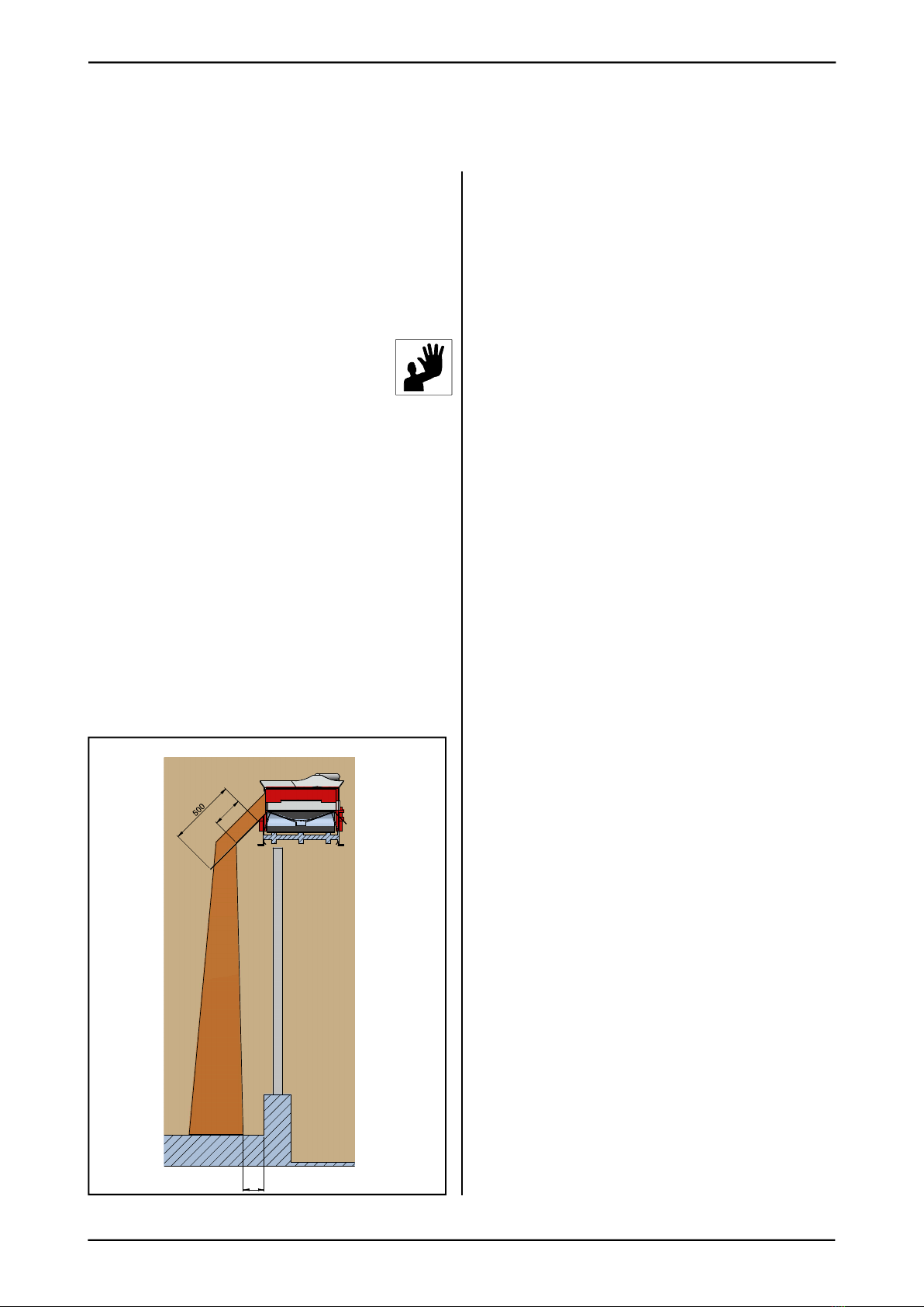
• The length of the guide plates must be
adjusted to ensure the best possible posi-
tioning of the feed on the bunk feeder. Cut if
necessary. See Fig. 5
Fig. 5

17
TKS Operator's manual
Recycling
- waste to resource -
TKS’s products rely on electrical and electronic components in order to work.
These fall under the generic term of EE products. TKS’s products use typical components such as
cables, switches, motors, control units, etc.
When TKS products are thrown away those components containing contaminants should be
treated and sorted in such a way that they do not pollute the environment. Contaminants should be
taken care of safely.
Distributors are obliged to accept EE waste from products in the range of goods they sell.
This waste should be kept safe and sent on to an approved waste recipient or treatment plant.
EE waste must be sorted and transported in such a way that it is not damaged or destroyed.
If you need further information on the treatment of EE waste, please contact your distributor.
Regards
TKS Agri AS
1.6

18
TKS Operator's manual
2 Operator's manual
• Decide how many feeding groups you need and how many times you wish to feed.
• TKS recommends a feeding group for milk cows and a group for each pen otherwise.
Number of feeding sessions:
Milk cows: Ten times a day
Calves and dry cows: Twice a day
Bulls: Four times a day
19
TKS Operator's manual
• When the FeedBelt is not in use, the screen on the PLS shows the time and date.
• This screen will appear if no key is pressed for two minutes.
• The main screen with the scrape position and side will appear when any key is pressed.
• Enter the menu by pressing the Enter key .
• Browse through the menu using the up and down keys ▲▼.
• Exit the menu using the Back key .
• On a screen containing values, the Enter key can be pressed to continue without changing a
value.
• Switch to the screen which shows the next feeding session by pressing the Back key when
the main screen is shown.
• If the cursor ( _ ) is fl ashing on the display, it means that the keypad must be used for entering
numbers.
• If the numbers have decimals, enter the entire number fi rst, followed by the decimal.
• Enter is used for moving the cursor to the next value.
• The keypad is used for activation of various functions in the menu. A number belongs then to a
functions. The number is shown in parentheses ( ) or to the right.
• The table on page 49 can be used to enter animal groups with reference to the keypad.
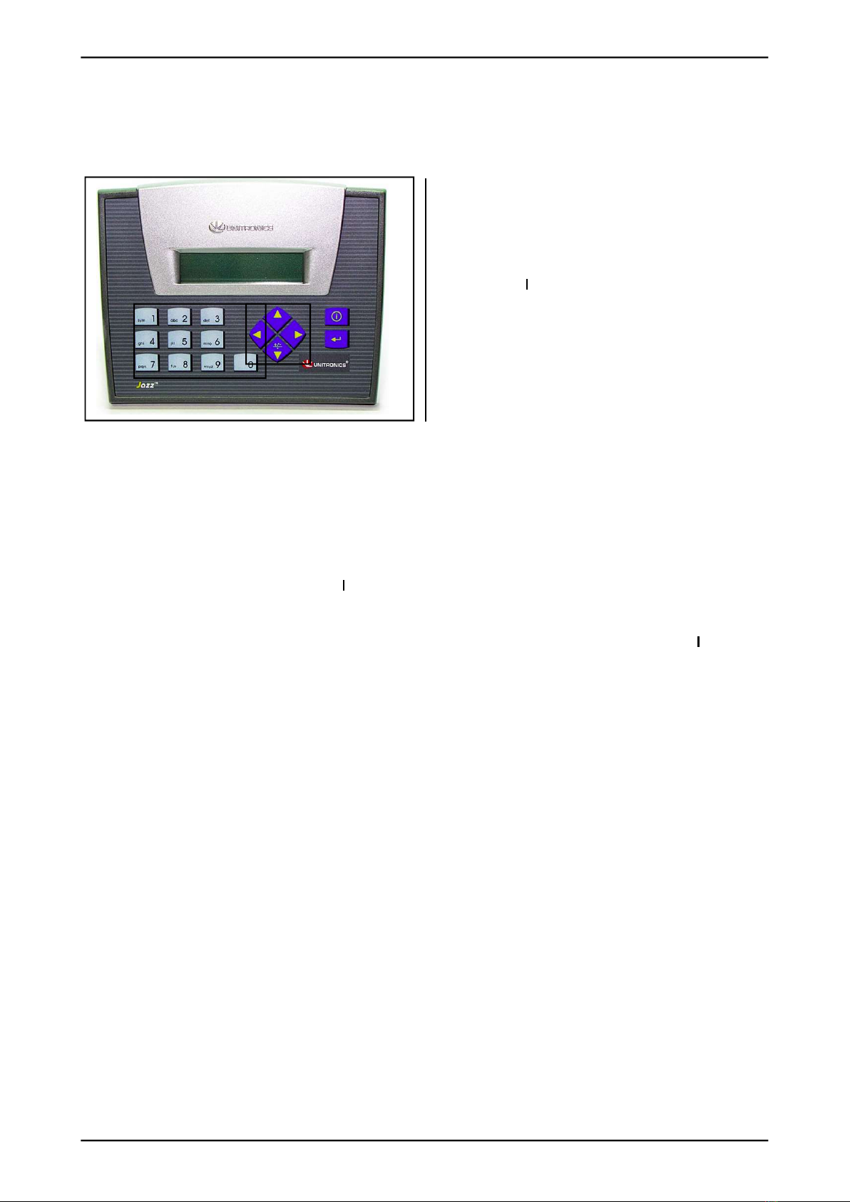
Screen and keyboard
PLS has two lines with non-coloured text on
the screen and a number keypad with a number
of function keys.
1. Numeric keypad – group number
2. Back key
3. Enter key
4. Up/down in the menu, browse menu▲▼
2.1 Use of the PLC - LITE
3
2
4
1
Fig. 6
20
TKS Operator's manual
2.2 Menu-tree PLC - LITE
Main screen Time to next feeding
Manual control Manual control
Groups Group number Group options Feed time
Settings FeedBelt setting
Calibration Confi rmation Calibration
SMS Enabling Phone number setting SMS function Status message
Time & Date Time / date settings
Table 1
Filling station
= Front End of operation
= Rear
Left feeding side (L)
Right feeding side (R)Shifting device
Fig. 7
Table of contents


